
Related Manuals for Thermal Arc 202 AC/DC


Summary of Contents for Thermal Arc 202 AC/DC
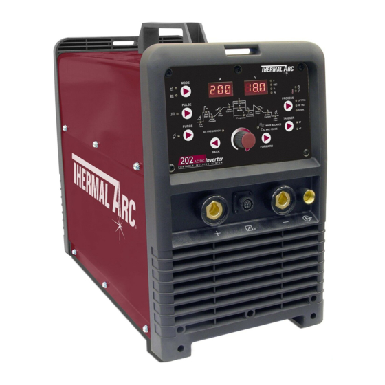
- Page 1 202 AC/DC inverter ArC welDing MAChine Operating Manual A-11401 Revision: AB Issue Date: August 6, 2012 Manual No.: 0-5239 Operating Features:...
- Page 2 YOU ARE IN GOOD COMPANY! The Brand of Choice for Contractors and Fabricators Worldwide. Thermal Arc is a Global Brand of Arc Welding Products for Victor Technologies We manufacture and supply to major welding industry sectors worldwide including; Manufacturing, Construction, Mining, Automotive, Aerospace, Engineering, Rural and DIY/Hobbyist.
- Page 3 Manufacturer assumes no liability for its use. Welding Power Supply Operating Manual Number 0-5239 for: Thermal Arc 202 AC/DC Part Number W1006305 Thermal Arc 202 AC/DC Package Part Number W1006306 Published by: Victor Technologies Europe Europa Building Chorley Industrial Park...
-
Page 4: Table Of Contents
202 AC/DC Power Source Controls, Indicators and Features ......3-4 3.09 202 AC/DC - STICK Programming Mode ............3-8 3.10 202 AC/DC – LIFT TIG and HF TIG Programming Mode ......3-10 3.11 Short Circuit Protection While Welding ............3-13 3.12 Victor Regulator .................... - Page 5 Routine Service and Calibration Requirements ..........5-2 5.04 Cleaning the Welding Power Source ............... 5-4 SECTION 6: KEY SPARE PARTS ................... 6-1 6.01 Power Source ....................6-1 APPENDIX: CIRCUIT DIAGRAM THERMAL ARC - LIMITED WARRANTY TERMS TERMS OF WARRANTY – JANUARY 2012...
-
Page 7: Safety Instructions And Warnings
SAFETY INSTRUCTIONS 202 AC/DC SECTION 1: SAFETY INSTRUCTIONS AND WARNINGS WARNING PROTECT YOURSELF AND OTHERS FROM POSSIBLE SERIOUS INJURY OR DEATH. KEEP CHILDREN AWAY. PACEMAKER WEARERS KEEP AWAY UNTIL CONSULTING YOUR DOCTOR. DO NOT LOSE THESE INSTRUCTIONS. READ OPERATING/INSTRUCTION MANUAL BEFORE INSTALLING, OPERATING OR SERVICING THIS EQUIPMENT. - Page 8 202 AC/DC SAFETY INSTRUCTIONS 2. Wear approved safety glasses. Side shields recommended. 3. Use protective screens or barriers to protect others WARNING from flash and glare; warn others not to watch the ARC RAYS can burn eyes and skin; NOISE arc.
- Page 9 SAFETY INSTRUCTIONS 202 AC/DC 3. Remove all flammables within 35 ft (10.7 m) of the welding arc. If this is not possible, tightly cover them with approved covers. WARNING 4. Be alert that welding sparks and hot materials from FUMES AND GASES can be hazardous to welding can easily go through small cracks and your health.
- Page 10 202 AC/DC SAFETY INSTRUCTIONS 1. Keep all doors, panels, covers, and guards 5. Use only correct shielding gas cylinders, closed and securely in place. regulators, hoses, and fittings designed for the specific application; maintain them and associated 2. Stop engine before installing or connecting parts in good condition.
-
Page 11: Principal Safety Standards
SAFETY INSTRUCTIONS 202 AC/DC NOTE 1.02 Principal Safety Standards Considerations About Welding And The Safety in Welding and Cutting, ANSI Standard Z49.1, Effects of Low Frequency Electric and from American Welding Society, 550 N.W. LeJeune Magnetic Fields Rd., Miami, FL 33126. -
Page 12: Symbol Chart
202 AC/DC SAFETY INSTRUCTIONS 1.03 Symbol Chart Note that only some of these symbols will appear on your model. Wire Feed Function Single Phase Wire Feed Towards Workpiece With Three Phase Output Voltage OFF. Three Phase Static Frequency Converter- Welding Gun... -
Page 13: Declaration Of Conformity
SAFETY INSTRUCTIONS 202 AC/DC 1.04 Declaration Of Conformity Manufacturer: Victor Technologies Inc Address: 16052 Swingley Ridge Road, Suite 300 St Louis, MO 63017 The equipment described in this manual conforms to all applicable aspects and regulations of the ‘Low Voltage Directive’... - Page 14 202 AC/DC SAFETY INSTRUCTIONS This Page Intentionally Blank SAFETY INSTRUCTIONS AND WARNINGS Manual 0-5239...
-
Page 15: Introduction
INTRODUCTION 202 AC/DC INVERTER SECTION 2: INTRODUCTION 2.02 Equipment Identification 2.01 How To Use This Manual The unit’s identification number (specification or To ensure safe operation, read the entire manual, part number), model, and serial number usually ap- including the chapter on safety instructions and pear on a nameplate attached to the control panel. -
Page 16: Description
2.06 Transporting Methods 2.04 Description This unit is equipped with a handle for carrying The Thermal Arc 202 AC/DC is a single phase constant purposes. current welding inverter capable of performing MMA (Stick), GTAW (HF TIG) and GTAW (Lift TIG) welding processes. -
Page 17: Specification
Open circuit voltage 70.3V DC / 50 VAC Protection Class IP23S Table 2-1: 202 AC/DC Specification NOTE Note 1: The Effective Input Current should be used for the determination of cable size & supply requirements. Note 2: Generator Requirements at the Maximum Output Duty Cycle. -
Page 18: Duty Cycle
(TIG & STICK) 100 110 120 130 140 150 160 170 180 190 200 210 220 Welding Current (AMPS) A-11402 Figure 2-2: 202 AC/DC Duty Cycle 2.10 Optional Accessories 26 Style TIG Torch with Remote Current Control . . Part No. W4013601 Foot Control 7.6 m . -
Page 19: Installation, Operation And Setup
INSTALLATION/SETUP 202 AC/DC INVERTER SECTION 3: INSTALLATION, OPERATION AND SETUP 3.01 Environment G. The enclosure design of this power source meets the requirements of IP23S as outlined in This machine is not designed for use in environments EN 60529. This provides adequate protection... -
Page 20: High Frequency Introduction
INSTALLATION/SETUP 202 AC/DC INVERTER 4. Re-Radiation from Unearthed Metallic Objects: A major factor contributing to interference is re- radiation from unearthed metallic objects close to the WARNING welding leads. Effective grounding of such objects will Any electrical work must be carried out by prevent re-radiation in most cases. - Page 21 INSTALLATION/SETUP 202 AC/DC INVERTER 3. Computer and other control equipment. 4. Safety critical equipment, e.g. guarding of industrial equipment. 5. The health of people around, e.g. the use of pacemakers and hearing aids. 6. Equipment used for calibration and measurement.
-
Page 22: 202 Ac/Dc Power Source Controls, Indicators And Features
INSTALLATION/SETUP 202 AC/DC INVERTER 3.08 202 AC/DC Power Source Controls, Indicators and Features MODE MODE VOLTS SECONDS PERCENT (%) POWER FREQ (Hz) FAULT Peak Amps Volts Current PULSE PROCESS PULSE PROCESS High Current LIFT TIG LIFT TIG Trough Start Base... - Page 23 INSTALLATION/SETUP 202 AC/DC INVERTER 1. Positive Welding Terminal Positive Welding Terminal. Welding current flows from the Power Source via heavy duty bayonet type terminals. It is essential, however, that the male plug is inserted and turned securely to achieve a sound electrical connection.
- Page 24 INSTALLATION/SETUP 202 AC/DC INVERTER 7. Process Selection Button The process selection control is used to select the desired welding mode. Three modes are available, GTAW (LIFT TIG), GTAW (HF TIG) and MMA (Stick) modes. Note that when the unit is powered off the mode selection control will automatically default to LIFT TIG for Stick or LIFT TIG modes and HF TIG for HF TIG mode.
- Page 25 INSTALLATION/SETUP 202 AC/DC INVERTER 9. Wave Balance / Arc Force Indicator This indicator light will illuminate when programming Wave Balance (AC HF TIG mode only) or Arc Force (STICK mode only). 10. Forward Programming Button Pressing this button will advance to the next step in the programming sequence.
-
Page 26: 202 Ac/Dc - Stick Programming Mode
Shielding Gas Supply. The Shielding Gas inlet is located on the rear of the Power Source. 22. Cooling Fan The 202 AC/DC is fitted with a cooling fan that will operate continuously when the On/Off switch on the rear panel is switched to the On position. - Page 27 INSTALLATION/SETUP 202 AC/DC INVERTER Programming Parameter Adjustment Device Display Hot Start This parameter operates in all weld modes except LIFT TIG mode and is used to heat up the weld zone in TIG modes or improve the Amps start characteristics for stick electrodes the...
-
Page 28: 202 Ac/Dc - Lift Tig And Hf Tig Programming Mode
INSTALLATION/SETUP 202 AC/DC INVERTER 3.10 202 AC/DC – LIFT TIG and HF TIG Programming Mode Press the PROCESS button to select LIFT TIG or HF TIG mode. Press the MODE switch to goggle between AC and DC welding output. The Programming LED's are always active. Press FORWARD or BACK to cycle through available programming functions. - Page 29 INSTALLATION/SETUP 202 AC/DC INVERTER Up Slope This parameter operates in (4T) TIG modes only and is used to set the time for the weld current Volts to ramp up, after the torch trigger switch has been pressed then 0.0 to 15.0 seconds released, from Initial Current to High or BASE current.
- Page 30 INSTALLATION/SETUP 202 AC/DC INVERTER Crater Current This parameter operates in (4T) TIG modes only and is used to set the finish current for TIG. Amps The CRATER Current remains ON until the torch trigger switch 5 to 200A (DC TIG mode)
-
Page 31: Short Circuit Protection While Welding
3.11 Short Circuit Protection While Welding To prolong the useful life of a TIG tungsten electrode, the 202 AC/DC incorporates special circuitry. In DC LIFT TIG mode, if the tungsten electrode touches the work the welding current is reduced to 40 Amps. - Page 32 INSTALLATION/SETUP 202 AC/DC INVERTER 2. The regulator body will be stamped “IN” or “HP” at the inlet port. Attach the inlet port to the system supply pressure connection. 3. Wrap pipe threads with Teflon tape 1 1/2 to 2 turns to effect a seal. If other sealants are used, they must be compatible with the gas that will be used in the system.
- Page 33 INSTALLATION/SETUP 202 AC/DC INVERTER WARNING Stand to the side of the cylinder opposite the regulator when opening the cylinder valve. Keep the cylinder valve between you and the regulator. For your safety, NEVER STAND IN FRONT OF OR BEHIND A REGULATOR WHEN OPENING THE CYLINDER VALVE! 9.
-
Page 34: Setup For Tig (Gtaw) Welding
INSTALLATION/SETUP 202 AC/DC INVERTER 3.13 Setup for TIG (GTAW) Welding A. Select Lift TIG or HF TIG mode with the process selection control (refer to Section 3.08.7 for further information). B. Connect the TIG Torch to the negative welding terminal (-). Welding current flows from the power source via heavy duty bayonet type terminals. - Page 35 INSTALLATION/SETUP 202 AC/DC INVERTER MODE PULSE PROCESS High Current LIFT TIG Base HF TIG Current Width Down Start Slope Slope STICK Current Initial Crater Frequency Current Current Post PURGE TRIGGER Flow Flow WAVE BALANCE AC FREQUENCY ARC FORCE BACK FORWARD...
-
Page 36: Setup For Stick (Mma) Welding
INSTALLATION/SETUP 202 AC/DC INVERTER 3.14 Setup for STICK (MMA) Welding A. Connect the Electrode Holder lead to the positive welding terminal (+). If in doubt, consult the electrode manufacturer. Welding current flows from the Power Source via heavy duty bayonet type terminals. It is essential, however, that the male plug is inserted and turned securely to achieve a sound electrical connection. -
Page 37: Basic Welding Guide
Electrodes are generally connected to the ELECTRODE HOLDER with the Electrode Holder connected positive polarity. The WORK LEAD is connected negative polarity and is connected to the work piece. If in doubt consult the electrode data sheet or your nearest Accredited Thermal Arc Distributor. Effects of Stick Welding Various Materials A. - Page 38 202 AC/DC INVERTER BASIC WELDING Metal Being Joined Electrode Comments Mild Steel E6011 This electrode is used for all-position welding or for welding on rusty, dirty, less-than-new metal. It has a deep, penetrating arc and is often the first choice for repair or maintenance work.
- Page 39 BASIC WELDING 202 AC/DC INVERTER Joint Preparations In many cases, it will be possible to weld steel sections without any special preparation. For heavier sections and for repair work on castings, etc., it will be necessary to cut or grind an angle between the pieces being joined to ensure proper penetration of the weld metal and to produce sound joints.
- Page 40 202 AC/DC INVERTER BASIC WELDING Place the work so that the direction of welding is across, rather than to or from, your body. The electrode holder lead should be clear of any obstruction so that you can move your arm freely along as the electrode burns down.
- Page 41 BASIC WELDING 202 AC/DC INVERTER Do not weave the electrode, but maintain a steady rate of travel along the joint sufficient to produce a well-formed bead. At first you may notice a tendency for undercut to form, but keeping the arc length short, the angle of the electrode at about 20º...
- Page 42 202 AC/DC INVERTER BASIC WELDING Art # A-07702 Art # A-07700_AB Figure 4-`14: Multi-runs in HV Fillet Weld Figure 4-16: Multi Run Vertical Fillet Weld C. Vertical Welds 1. Vertical Up Tack weld a three feet length of angle iron to your work bench in an upright position.
- Page 43 BASIC WELDING 202 AC/DC INVERTER Art # A-07704 Figure 4-18: Overhead Fillet Weld Distortion Distortion in some degree is present in all forms of welding. In many cases it is so small that it is barely perceptible, but in other cases allowance has to be made before welding commences for the distortion that will subsequently occur.
- Page 44 202 AC/DC INVERTER BASIC WELDING Weld Permanent Upset Art # A-07706_AB Contraction with tension Figure 4-20: Parent Metal Contraction Art # A-07707 Figure 4-21: Principle of Presetting Overcoming Distortion Effects There are several methods of minimizing distortion Art # A-07708 effects.
-
Page 45: Stick (Mma) Welding Troubleshooting
BASIC WELDING 202 AC/DC INVERTER Art # A-07428_AB Figure 4-26: Chain Intermittent Welding Art # A-07713_AB Figure 4-27: Staggered Intermittent Welding 4.02 Stick (MMA) Welding Troubleshooting FAULT CAUSE REMEDY 1 Welding current ARC FORCE control knob Reduce the ARC FORCE control knob until weld-... - Page 46 202 AC/DC INVERTER BASIC WELDING Art: A-04971 Figure 1-Example of insufficient gap or incorrect sequence 4 A groove has been A Welding current is too A Reduce welding current. formed in the base high. metal adjacent to B Welding arc is too long.
-
Page 47: Tig (Gtaw) Basic Welding Technique
BASIC WELDING 202 AC/DC INVERTER 7 Crack occurring in A Rigidity of joint. A Redesign to relieve weld joint of severe stresses weld metal soon or use crack resistance electrodes. after solidification B Insufficient throat thick- B Travel slightly slower to allow greater build up in commences ness. - Page 48 202 AC/DC INVERTER BASIC WELDING Guide for Selecting Filler Wire Diameter Filler Wire Diameter DC Current Range (Amps) 1/16” (1.6mm) 20-90 3/32” (2.4mm) 65-115 1/8” (3.2mm) 100-165 3/16” (4.8mm) 200-350 Table 4-4: Filler Wire Selection Guide Tungsten Electrode Types Electrode Type...
-
Page 49: Tig (Gtaw) Welding Problems
Arc Welding section are applicable a comprehensive outline of the TIG Welding process is outside the scope of this Operating Manual. For further information please refer to www. victortechnologies.com or contact Thermal Arc. 4.04 TIG (GTAW) Welding Problems... - Page 50 202 AC/DC INVERTER BASIC WELDING 6 Electrode melts or oxidises A Torch lead connected A Connect torch lead to negative welding when an arc is struck. to positive welding terminal. terminal. B No gas flowing to weld- B Check the gas lines for kinks or breaks ing region.
-
Page 51: Power Source Problems And Routine Service Requirements
If major complex subassemblies are faulty, then the Welding Power Source must be returned to an ac- credited Thermal Arc Service Provider for repair. The basic level of troubleshooting is that which can be performed without special equipment or knowledge. Refer also to section 4 for solving welding problems. -
Page 52: Routine Service And Calibration Requirements
The inspection and testing of the power source and associated accessories shall be carried out in accordance with Section 5 of EN 60974.1: Safety in Welding and Allied Processes-Part 2 Electrical. This includes an in- sulation resistance test and an earthing test to ensure the integrity of the unit is compliant with Thermal Arc original specifications. - Page 53 EN 60974.1, then the above tests should be carried out prior to entering this location. B. Calibration Requirements Where applicable, the tests outlined in Table 5-3 below shall be conducted by an accredited Thermal Arc service provider. Testing Requirements...
-
Page 54: Cleaning The Welding Power Source
202 AC/DC INVERTER SERVICE Periodic calibration of other parameters such as timing functions are not required unless a specific fault has been identified. C. Calibration Equipment All equipment used for Power Source calibration shall be in proper working condition and be suitable for conducting the measurement in question. -
Page 55: Key Spare Parts
SPARE PARTS 202 AC/DC INVERTER SECTION 6: KEY SPARE PARTS 6.01 Power Source A-11408 Figure 6-1 Manual 0-5239 KEY SPARE PARTS... - Page 56 202 AC/DC INVERTER SPARE PARTS 202 AC/DC Spare Parts Item Part Number Description W7005500 PCB display W7005502 PCB HF W7005503 PCB aux power supply W7005504 PCB primary inverter W7005505 PCB AC output drive W7005506 PCB control W7005507 PCB secondary rectifier...
-
Page 57: Appendix: Circuit Diagram
APPENDIX 202 AC/DC INVERTER APPENDIX: CIRCUIT DIAGRAM ACOUT ACPOUT QF/HF POWER J2 (10) POWER/FJ POWER SUPPLY BOARD DC-IN JB (10) A-11227_AB Manual 0-5239 APPENDIX... - Page 59 The warranty period begins on the date of sale to the end user. Welding Equipment - Limited Warranty Period Product Period Thermal Arc 202AC/DC 2 Years TIG Torch, Electrode Holder & Work Lead 30 Days MIG Gun Consumables If warranty is being sought Victor Technologies must be notified in writing within 30 days of the failure and at such time we will make arrangements to fulfil the warranty claim.
- Page 60 THE AMERICAS Denton, TX USA U.S. Customer Care Ph: 1-800-426-1888 (tollfree) Fax: 1-800-535-0557 (tollfree) International Customer Care Ph: 1-940-381-1212 Fax: 1-940-483-8178 Miami, FL USA Sales Office, Latin America Ph: 1-954-727-8371 Fax: 1-954-727-8376 Oakville, Ontario, Canada Canada Customer Care Ph: 1-905-827-4515 Fax: 1-800-588-1714 (tollfree) EUROPE Chorley, United Kingdom...
Need help?
Do you have a question about the 202 AC/DC and is the answer not in the manual?
Questions and answers