
Related Manuals for HITEC Flash 7


Summary of Contents for HITEC Flash 7
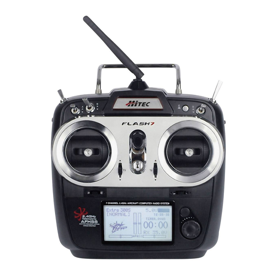
- Page 1 7 Channel 2.4 GHz Aircraft Computer Radio System 7 Channel 2.4 GHz Aircraft Computer Radio System OPERATION MANUAL ver. 1.0...
-
Page 2: Before Using
Important Notices Please note that Hitec reserves the right to make production changes during the life of our product lines that may impact the information in this manual. For the most up-to-date information on this and any other Hitec product, visit our web site at www.hitecrcd.com. -
Page 3: Table Of Contents
7 Channel 2.4 GHz Aircraft Computer Radio System Table of Contents Introduction Safety Information........................6 Product Support..........................7 Steps for Successfully Programming the Flash 7 Radio...........8 System Component Specifications..................9 Terms and Icons...........................10 Powering the Flash 7........................11 Transmitter Controls........................11 Main Menu.............................12 Transmitter Warnings.........................12 Maxima Series Receivers......................13... - Page 4 7 Channel 2.4 GHz Aircraft Computer Radio System Table of Contents Common Model Programming Menu Working with the Common Model Function Menus........43 Servo Reverse....................44 Sub Trims......................44 Dual Rates and Exponentials................45 Switch Assignment...................47 End Point Adjustments ...................47 Servo Speed ......................48 Programmable Mixes ..................48 Timers........................51 Servo Monitors....................54 Throttle Lock......................55...
- Page 5 7 Channel 2.4 GHz Aircraft Computer Radio System Table of Contents Helicopter Programming Helicopter Programming Menu..............80 Flight Conditions....................80 Throttle Cut.......................82 Throttle Hold.....................83 Gyro........................84 Revolution Mixing....................86 Swash to Throttle Mixing................88 Swash Mixing....................90 Throttle Curve....................91 Pitch Curve......................93 Swash Ring......................95 Using the Telemetry System Working with the Sensor Menu..............96 GPS........................96 RPM........................97...
- Page 6 We are sure you will find the Flash 7 one of the easiest radios to program. Please review this entire manual to learn how to safely use your new radio.
-
Page 7: Safety Information
7 Channel 2.4 GHz Aircraft Computer Radio System Safety Information Flying models can be dangerous if proper safety precautions are not followed. Here are a few critical safety suggestions to keep you and others safe. Are you experienced? Flying models is not an intuitive process. Most accomplished model pilots were taught by another modeler. -
Page 8: Product Support
Hitec Web Site Make plans to visit the Hitec web site on a regular basis at www.hitecrcd.com. There you will find specs and other information about the entire Hitec product line, and soon our FAQ pages will hold valuable information about the Flash 7. -
Page 9: Steps For Successfully Programming The Flash 7 Radio
User Interface User Interface The Flash 7 utilizes a jog dial/push button and a back button to access the various functions and input settings in the radio. The jog dial/push button is used to scroll through screens and programming features. Press the jog dial to enter a menu, activate or confirm a setting. Pressing the back button takes you to the previous screen or function. -
Page 10: System Component Specifications
After following along with the quick start guide you will have a feel for the way the Flash 7 programming is laid out. We encourage you to set up a few aircraft before you fly the Flash 7. -
Page 11: Terms And Icons
Terms and Icons Glossary of Terms AFHSS 2.4GHz Signal: Hitec’s 2.4GHz R/C signal protocol. Adaptive Frequency Hopping Spread Spectrum. Telemetry: Data signal from the model, transmitted to the transmitter. Range Check: A ground check of the signal strength between the transmitter and receiver done before flying. -
Page 12: Powering The Flash 7
LiPo 7.0 Volts LiFe 6.0 Volts Power Meter On the home screen of the Flash 7 you can visually see the voltage reading as well as a bar indicating the amount of power left in the battery. Transmitter Controls Switch B... -
Page 13: Main Menu
Spectra Reciever Type to access the Spectra menu. Time to access the Timers menu. Transmitter Warnings The Flash 7 has a few warning alarms that you should be aware of. Start Up Warnings High Throttle If the throttle is positioned above idle during the system “boot- up to transmit”... -
Page 14: Maxima Series Receivers
Caution Note MAXIMA 6 MAXIMA 9 1. Function Button: Used for binding the receiver to the Flash 7 and entering the FAIL-SAFE or Hold MA XI MA 9 MA XI MA 6 feature. 2. Dual LED Status Indicator: Indicates the set-up process codes and current status of the receiver. - Page 15 7 Channel 2.4 GHz Aircraft Computer Radio System Maxima Series Receiver Connection Diagrams Your Hitec AFHSS system uses a communication protocol that links and binds the Hitec 2.4GHz receiver to your transmitter. Once the receiver and transmitter are “bound”, no other transmitter can interfere with your receiver during its operation.
-
Page 16: Optima And Minima Receivers
(6L utilizes a soft case and exposed output block) exposed output block 1. Function Button: Used for binding the receiver to a module or Hitec 2.4 built-in transmitters, entering the FAIL-SAFE or Hold feature. 2. Dual LED: Status Indicator: Indicates the set-up process codes and current status of the receiver. - Page 17 7 Channel 2.4 GHz Aircraft Computer Radio System Optima and Minima Series Receivers cont. Compatibility: The OPTIMA & MINIMA receivers are compatible with transmitters using the Hitec AFHSS 2.4 GHz system, such as, Spectra 2.4 module or dedicated built-in module AFHSS 2.4 Hitec transmitters. FAIL-SAFE/Hold Mode Selectable: Servos and other accessories can be set with a FAIL-SAFE point if power to the receiver is lost.
- Page 18 Optima and Minima Series Receiver Link (ID-Setting or Bind) Your Hitec AFHSS system uses a communication protocol that links and binds the Hitec 2.4GHz receiver to your transmitter. Once the receiver and transmitter are “bound”, no other transmitter can interfere.
- Page 19 7 Channel 2.4 GHz Aircraft Computer Radio System Optima and Minima Series Receiver Link (ID-Setting or Bind) cont. When the binding process is completed, it When the LED stops blinking, press the jog automatically goes to the finish screen. (The dial to get to the next screen.
-
Page 20: Fail Safe And Hold Mode Setup
7 Channel 2.4 GHz Aircraft Computer Radio System FAIL-SAFE and Hold Mode Setup If the FAIL-SAFE function is set up and used properly but the receiver signal is somehow interrupted, the servos will move to your previously stored FAIL-SAFE setup. If you do not activate the FAIL-SAFE function, the signal is switched off after the HOLD period of 1 sec. -
Page 21: Telemetry System
Optima 6) and include a Low Receiver Battery Warning as a basic function. Functions (Available with Optima 7 and 9): Hitec offers a wide variety of telemetry sensors designed to work with both fuel and electric powered aircraft. Check our website at www.hitecrcd.com for the latest available telemetry accessories. -
Page 22: Range Check Function
7 Channel 2.4 GHz Aircraft Computer Radio System Range Check Function It is critical that before each flight session you perform a range check that confirms the signal between the receiver and transmitter is appropriate. To do a range check, use a power-down mode to reduce the transmitter signal strength. -
Page 23: Scan Mode Function
7 Channel 2.4 GHz Aircraft Computer Radio System Scan Mode In Scan Mode the transmitter and receiver will scan all available channels every time you turn it on. It will then choose the cleanest frequencies to use. Scan Mode is preferable to use when flying in a crowded 2.4GHz environment. -
Page 24: Slt System
SLT Technology In addition to our proprietary AFHSS technology the Flash 7 has the ability to transmit using Secure Link Technology (SLT). This allows you to fly the numerous Tx-Ready models available on the market. For more information visit Tx-Ready.com for models utilizing this technology. -
Page 25: Quick Start Guides
The operations shown during this exercise will help you understand many of the basic programming steps used by the Flash 7. If you are setting up a powered or un-powered glider, we will be programming your plane into the ACRO menu for this exercise. - Page 26 7 Channel 2.4 GHz Aircraft Computer Radio System Airplane Quick Start Guide cont. We are programming a new model into the model memory slot number two, not the model memory slot one. For the purpose of this exercise it will ensure a fresh model memory with no existing programming.
-
Page 27: Helicopter Quick Start Guide
The following information is designed to guide you through a simple setup of a basic 120 cyclic collective pitch mixing (CCPM) helicopter with a fly bar. The operations shown during this exercise will help you understand many of the basic programming steps used by the Flash 7 when programming a basic helicopter setup. - Page 28 7 Channel 2.4 GHz Aircraft Computer Radio System Helicopter Quick Start Guide cont. 5. Select the first default model (NONAME-1) and press the jog dial to bring up the model maintenance prompts. Select “NEW” to create a new model. We are programming a new model into the model memory slot number two, not the model memory slot one.
-
Page 29: System Menu Programming
7 Channel 2.4 GHz Aircraft Computer Radio System System Menu There are two primary menus in the Flash 7 programming structure. The System function Menu and the Model function Menu. The first menu we will explore is the System Menu. This menu has all the common programming function that are available for ACRO, GLID and HELI models. -
Page 30: Working With The System Menu
7 Channel 2.4 GHz Aircraft Computer Radio System System Menu cont. UI FEEDBACK: Turns the user interface sound feedback on or off. WARNING SETUP: Controls the various transmitter warnings RF CHECK: Prompts if you are “Ready to Transmit” HIGH THROTTLE: Warns if the throttle is not in “idle” position FLIGHT CONDITION: Warns if a flight condition switch is on INFO: Displays transmitter information such as software version. - Page 31 7 Channel 2.4 GHz Aircraft Computer Radio System Model Select Menu cont. 1. Create a new model: When you create a new model, you are also prompted to do other setup items. To avoid repetitive information it is recommended that you read the quick start guides in order to understand what other steps are required when creating a new model.
- Page 32 7 Channel 2.4 GHz Aircraft Computer Radio System Model Select Menu cont. 4. Reset the active model memory slot to factory default settings: a. Select the model you wish to reset. b. Scroll to “RESET” and press the jog dial. c.
-
Page 33: Model Type Menu
“create a new model” process plus all the default features. Here we can define all the choices you have while setting up your aircraft in the Flash 7. There are three types of aircraft “Model Type” menus: ACRO: For all fixed wing, glow, gas and some electric powered models. -
Page 34: Model Type Glid Menu Programming
7 Channel 2.4 GHz Aircraft Computer Radio System Model Type ACRO Menu Programming cont. Additionally there are setups for delta wing type models (Elevon): 2AILE 2AILE+1FLAP 2AILE+2FLAP 5. Once you have selected your wing types, press the jog dial to confirm your selection. 6. - Page 35 7 Channel 2.4 GHz Aircraft Computer Radio System Model Type GLID Menu Programming cont. 4. Once in the GLID setup menu you will set your wing and tail choices. Scroll to the wing selection and press the jog dial to activate the selections and scroll through the choices.
-
Page 36: Model Type Heli Menu Programming
7 Channel 2.4 GHz Aircraft Computer Radio System Model Type HELI Menu Programming 1. From the System Menu select MDL TYPE. 2. Press the jog dial once to enter the Model Type Selection Menu and scroll to HELI. 3. Press the jog dial once to enter the HELI setup menu. to enter the HELI setup menu. -
Page 37: Channel Selection Menu
The Flash 7 has two Virtual Channels VC1 & VC2. The virtual channels can only be assigned to a transmitter control and then mixed with another channel in the programmable mix function. -
Page 38: Trim Step
The Flash 7 can be paired with another Hitec transmitter to create a master/slave setup that is useful when instructing student pilots. The Flash 7 can be used to help teach students how to fly utilizing the various trainer functions of the transmitter. - Page 39 Trainer Function cont. Within the trainer menu, you can set the Flash 7 as a “Master radio”, set the trainer switch, and activate the other features. To do this, the transmitter must be in transmit mode. If not in the transmit mode, the only options you will have are the “pupil”...
- Page 40 Telemetry System on page 96 for more information. Spectra The spectra menu is utilized to manage the interface between the Flash 7 transmitter and the receiver for each aircraft. This includes specifying the receiver type, performing a range check, binding the receiver, and specifying a frequency scan.
-
Page 41: Control Modes
7 Channel 2.4 GHz Aircraft Computer Radio System Control Modes The Flash 7 is capable of operating in control Modes 1 ~ 4. The default is mode 2 for models sold in North America as this is generally preferred by the majority of pilots. - Page 42 The operating voltages of Alkaline and NiCd/NiMh batteries are below the safe discharge voltages for LiFe and LiPo battery types. Selecting a LiFe or LiPo battery type in the menu when the actual battery is Alkaline or NiCd/NiMh will cause the Flash 7 to shut down due to low- Warning voltage settings.
- Page 43 7 Channel 2.4 GHz Aircraft Computer Radio System Management Menu cont. 15. Scroll to highlight “FLIGHT CONDITION” and press the jog dial to activate the menu. 16. Scroll to select “ON” or “OFF”. When the flight condition warning is turned on, the radio will warn you if any programmed flight conditions are active when the unit is powered on.
-
Page 44: Common Model Programming Menu
7 Channel 2.4 GHz Aircraft Computer Radio System Common Model Programming Menu The Model Function menu contains options that relate to all model types (common) as well as options which are specific to fixed wing models (ACRO/GLID) or helicopters (HELI). This section illustrates the common model function options. -
Page 45: Servo Reverse
7 Channel 2.4 GHz Aircraft Computer Radio System Servo Reverse The Reverse screen allows you to specify the direction of servo rotation for channels 1-7 of the active model. 1. From the model menu, scroll to highlight “REVERSE” and press the jog dial once to enter the reverse menu. -
Page 46: Dual Rates And Exponentials
7 Channel 2.4 GHz Aircraft Computer Radio System Dual Rates and Exponentials The Dual Rate (D/R) feature provides a method to define two different values of servo movement (“rates”) on the same channel. You may want low control rates during takeoff and landing and higher rates when performing aerobatics. - Page 47 7 Channel 2.4 GHz Aircraft Computer Radio System Dual Rates cont. 8. Scroll to highlight the “R/D” (right/down) field and press the jog dial to activate the menu. 9. Rotate the jog dial to increase (clockwise) or decrease (counter-clockwise) the desired travel for the servo(s) in high-rate mode.
-
Page 48: Switch Assignment
7 Channel 2.4 GHz Aircraft Computer Radio System Switch Assignment 17. Scroll to highlight the S/W field and press the jog dial to activate the menu. 18. Scroll to select the switch you have chosen to control dual rates for this function and press the jog dial to confirm your selection. -
Page 49: Servo Speed
Programmable Mixes The Flash 7 provides three user-programmable mixes which can be used for a wide variety of custom functions that are not available with the built-in mixes and options. A common use for these mixes is to correct unwanted behavior of an aircraft. - Page 50 7 Channel 2.4 GHz Aircraft Computer Radio System Programmable Mixes cont. Example: Let’s say you want to control your ailerons as flaps using one of the slider switches but you don’t want to have the slider active all the time in case you accidentally bump it. You can assign the slider to your virtual channel and then P-mix that channel to the aileron servos.
- Page 51 7 Channel 2.4 GHz Aircraft Computer Radio System Programmable Mixes cont. 10. Scroll to highlight the “L/U” (left/up) field and press the jog dial to activate the selection. 11. Rotate the jog dial to increase (clockwise) or decrease (counter-clockwise) the desired left (AILE, RUDD) or up (ELEV) servo movement for the slave function.
-
Page 52: Timers
In addition, there is an integrated timer for each model memory that automatically records the length of time that the Flash 7 is used for that model. All timers are displayed on the home screen. To configure a timer: 1. - Page 53 7 Channel 2.4 GHz Aircraft Computer Radio System Timers cont. 2. Scroll to highlight “INH” under TIMER-1 and press the jog dial to activate the menu. 3. Scroll to select “ACT” (active) and press the jog dial to confirm your selection. 4.
- Page 54 7 Channel 2.4 GHz Aircraft Computer Radio System Timers cont. 14. Scroll to select the desired activation switch for the timer. Press the jog dial to confirm your selection. a. Selecting “NULL” will cause the timer to be inactive. b. If you selected a switch, the switch position menu will appear. - Scroll to highlight the switch position(s) that you will use to activate the timer.
-
Page 55: Servo Monitors
Servo Monitors The Monitor function will display a graphic representation of all seven channels as they are manipulated with the Flash 7’s controls. There are also channel cycling and neutralization functions. 1. From the model menu, scroll to highlight “MONITOR” and press the jog dial once to enter the monitor menu. -
Page 56: Throttle Lock
Throttle Lock The Flash 7 features a “throttle lock” function that can be activated when the transmitter is transmitting a signal. We encourage you to use the throttle lock feature as a safety precaution against “accidental throttle application”. -
Page 57: Acro And Glider Programming Menu
7 Channel 2.4 GHz Aircraft Computer Radio System Acro and Glider Programming Menu When the active model is configured as a fixed-wing (ACRO or GLID) model type, the Model Function menu contains programming options which are useful for fixed-wing aircraft. This section describes the features and programming steps for the ACRO and GLID model function menus. -
Page 58: Flight Conditions
Flight Conditions The Flash 7 allows you to program up to four flight conditions. This powerful feature lets you define customized trim values and mix settings for different phases of flight. The flight conditions for fixed wing aircraft are:... -
Page 59: Aileron Differentials
7 Channel 2.4 GHz Aircraft Computer Radio System Flight Conditions cont. If more than one flight condition is concurrently enabled, the condition with the highest number (per the table shown above) will be active. The field just below the model icon on the Home screen indicates the active flight condition. -
Page 60: Elevon Mixing
6. Press the back button to return to the model function menu. Elevon Mixing Flying wing aircraft are most often set up using elevon control surfaces. The Flash 7 mixes the aileron and elevator functions to provide this configuration with just one flight control surface per wing panel. -
Page 61: V-Tail Mixing
7 Channel 2.4 GHz Aircraft Computer Radio System Elevon Mixing cont. 7. Press the back button to return to the elevon mix menu. 8. Scroll to the top “ELEV” field and press the jog dial to activate the menu. 9. Scroll to highlight the “L/U” (left/up) field and press the jog dial to activate the menu. - Page 62 7 Channel 2.4 GHz Aircraft Computer Radio System V-Tail Mixing cont. 3. Scroll to highlight the “L/U” (left/up) field and press the jog dial to activate the menu. 4. Rotate the jog dial to increase (clockwise) or decrease (counter-clockwise) the desired endpoint for the servo attached to the “ELEV”...
-
Page 63: Ailevator Mixing
7 Channel 2.4 GHz Aircraft Computer Radio System Ailevator Mixing The Ailevator feature allows the configuration of a two-servo or “split” elevator setup. It also features an “aileron to split elevator” mix which allows the elevators to provide roll control. This feature, also called “tailerons”, is commonly used on jet models. -
Page 64: Aileron To Rudder Mixing
7 Channel 2.4 GHz Aircraft Computer Radio System Ailevator Mixing cont. 11. Scroll to highlight the “R/D” (right/down) field and press the jog dial to activate the menu. 12. Rotate the jog dial to increase (clockwise) or decrease (counter-clockwise) the desired servo endpoint when a right roll command is given. - Page 65 7 Channel 2.4 GHz Aircraft Computer Radio System Aileron to Rudder Mixing cont. 7. Scroll to highlight the “R/D” (right/down) field and press the jog dial to activate the menu. 8. Rotate the jog dial to increase (clockwise) or decrease (counter-clockwise) the desired rudder travel when a right roll command is given.
-
Page 66: Elevator To Camber Mixing
7 Channel 2.4 GHz Aircraft Computer Radio System Aileron to Rudder Mixing cont. c. If you choose “Cond” (Flight Condition): - The upper right field of the menu displays which flight condition is currently active and will be programmed. - Scroll to the Flight Condition field and press the jog dial to activate the menu. - Page 67 7 Channel 2.4 GHz Aircraft Computer Radio System Elevator to Camber Mixing cont. 7. Scroll to the top row of the value table (“AILE”) and press the jog dial to activate the menu. 8. Scroll to highlight the “L/U” (left/up) field and press the jog dial to activate the menu.
- Page 68 7 Channel 2.4 GHz Aircraft Computer Radio System Elevator to Camber Mixing cont. 18. Scroll to select “FLAP” and press the jog dial to confirm your selection. 19. Repeat steps 5-15 to configure the flap movements for this mix. If using only one flap servo, configure only the “FLAP” row of the value table.
-
Page 69: Camber Mixing (Glid Only)
7 Channel 2.4 GHz Aircraft Computer Radio System Elevator to Camber Mixing cont. 22. Press the back button to return to the model function menu. To disable the elevator-to-camber mix: 1. Scroll to highlight the “MIX” field in the elevator-camber mix menu and press the jog dial to activate the menu. - Page 70 7 Channel 2.4 GHz Aircraft Computer Radio System Camber Mixing (GLID Only) cont. 10. Scroll to highlight the “FLAP” field and press the jog dial to activate the menu. 11. Rotate the jog dial to input the desired travel for the “FLAP” servo when camber is active.
-
Page 71: Flap Control
7 Channel 2.4 GHz Aircraft Computer Radio System Camber Mixing (GLID Only) cont. You may also select a flight condition in this menu by activating the desired flight condition. aution Note - Repeat steps 4-18 to define the settings for each flight condition. 17. -
Page 72: Offset
7 Channel 2.4 GHz Aircraft Computer Radio System Flap Control 7. Scroll to highlight the “R/D” (right/down) field and press the jog dial to activate the menu. 8. Rotate the jog dial to increase (clockwise) or decrease (counter-clockwise) the desired servo endpoint for when the flap is fully deployed. -
Page 73: Butterfly Mixing (Glid Only)
7 Channel 2.4 GHz Aircraft Computer Radio System Offset cont. 2. Press the jog dial again to activate the menu. 3. Rotate the jog dial to select “ACT” (activate), then press the jog dial to confirm your selection and activate the offset menu. 4. - Page 74 7 Channel 2.4 GHz Aircraft Computer Radio System Butterfly Mixing (GLID Only) cont. To configure butterfly: 1. From the model menu, rotate the jog dial to highlight “B-Fly” and press the jog dial once to enter the activation menu. 2. Press the jog dial again to activate the menu. 3.
- Page 75 7 Channel 2.4 GHz Aircraft Computer Radio System Butterfly Mixing (GLID Only) cont. 16. Scroll to the “S/W” field and press the jog dial twice to activate the menu. 17. Scroll to select a switch to activate the butterfly mix. Press the jog dial to confirm your selection.
-
Page 76: Gyro
7 Channel 2.4 GHz Aircraft Computer Radio System Butterfly Mixing (GLID Only) cont. - Scroll to select the middle value field and press the jog dial to activate the menu. - Rotate the jog dial to position the top of the bar graph at the throttle position where the mix will be enabled. -
Page 77: Throttle Cut (Acro Only)
7 Channel 2.4 GHz Aircraft Computer Radio System Gyro cont. 6. Scroll to highlight “S/W” and press the jog dial to activate the switch menu. 7. Scroll to select a switch to control the gyro. Press the jog dial to confirm your selection. a. - Page 78 7 Channel 2.4 GHz Aircraft Computer Radio System Throttle Cut (Acro Only) cont. To configure throttle cut: 1. From the model menu, rotate the jog dial to highlight “THRO CUT” and press the jog dial once to enter the activation menu. 2.
-
Page 79: Throttle Curve
7 Channel 2.4 GHz Aircraft Computer Radio System Throttle Cut (Acro Only) cont. 8. Press the back button to return to the model function menu. To disable throttle cut: 1. Scroll to highlight the “MIX” field in the throttle cut menu and press the jog dial to activate the menu. - Page 80 7 Channel 2.4 GHz Aircraft Computer Radio System Throttle Curve cont. b. If you choose a switch: - The current switch position will be displayed in the top right field of the display as “0”, “1”, or “2”. - Repeat steps 4-8 to define throttle curve for every switch position. 11.
-
Page 81: Helicopter Programming Menu
Flight Conditions The Flash 7 allows you to program up to four flight conditions. This powerful feature lets you define customized trim values and mix settings for different phases of flight. - Page 82 7 Channel 2.4 GHz Aircraft Computer Radio System Flight Conditions cont. The following features support flight condition programming in HELI mode: Gyro Revolution Mix Swash > Throttle Mix Throttle Curve Pitch Curve 1. From the model menu, rotate the jog dial to highlight “F.COND”...
-
Page 83: Throttle Cut
7 Channel 2.4 GHz Aircraft Computer Radio System Flight Conditions cont. If more than one flight condition is concurrently enabled, the condition with the highest number (per the table shown above) will be active. The field just below the model icon on the Home screen indicates the active flight condition. -
Page 84: Throttle Hold
7 Channel 2.4 GHz Aircraft Computer Radio System Throttle Cut cont. 4. Scroll to the “POS” (position) field and press the jog button to activate the menu. 5. Rotate the jog dial to input the desired position of the throttle servo when throttle cut is activated. -
Page 85: Gyro
Gyro It is often desirable to use a gyro to help stabilize the tail rotor on helicopters. The Flash 7 provides up to three gyro sensitivity settings per model memory. The gyro setting can also be specified for each defined flight condition. - Page 86 7 Channel 2.4 GHz Aircraft Computer Radio System Gyro cont. 3. Rotate the jog dial to select ACT (activate), then press the jog dial to confirm your selection and activate the GYRO menu. 4. Scroll to the “MODE” field and press the jog button to activate the menu.
-
Page 87: Revolution Mixing
7 Channel 2.4 GHz Aircraft Computer Radio System Gyro cont. b. If you choose a switch: - The current switch position will be displayed next to the rate which is currently activated by the switch’s position. - Repeat step 5a or 5b as applicable to define gyro rate for every switch position. - Page 88 7 Channel 2.4 GHz Aircraft Computer Radio System Revolution Mixing cont. 4. Scroll to the “RATE” field and press the jog button to activate the menu. 5. Scroll to highlight the “L/U” (left/up) field and press the jog dial to activate the menu. 6.
-
Page 89: Swash To Throttle Mixing
7 Channel 2.4 GHz Aircraft Computer Radio System Revolution Mixing cont. c. If you choose “Cond” (Flight Condition): - The upper right field of the menu displays which flight condition is currently active and will be programmed. - Scroll to the Flight Condition field and press the jog dial to activate the menu. - Page 90 7 Channel 2.4 GHz Aircraft Computer Radio System Swash to Throttle Mixing cont. 4. Scroll to the function field (“AILE” or “ELEV”). If “AILE” is not the current function, press the jog dial to activate the menu. Otherwise, skip to step 6. 5.
-
Page 91: Swash Mixing
7 Channel 2.4 GHz Aircraft Computer Radio System Swash to Throttle Mixing cont. 17. Scroll to select a switch to activate the swash-throttle mix. Press the jog dial to confirm your selection. a. If you choose the “NULL” option, the set mix values will remain active at all times for this model. b. -
Page 92: Throttle Curve
7 Channel 2.4 GHz Aircraft Computer Radio System Our example will show a 120CCPM head format. 1. From the model menu, scroll to highlight “Swash Mix” and press the jog dial once to enter the sub trim menu. 2. Scroll to the functions (AILE,ELEV,Pitch) to be adjusted and press the jog dial to activate the menu. - Page 93 7 Channel 2.4 GHz Aircraft Computer Radio System Throttle Curve cont. 2. Press the jog dial again to activate the menu. 3. Rotate the jog dial to select ACT (activate), then press the jog dial to confirm your selection and activate the throttle curve menu.
-
Page 94: Pitch Curve
7 Channel 2.4 GHz Aircraft Computer Radio System Throttle Curve cont. - Scroll to the flight condition field and press the jog dial to activate the menu. - Choose the desired flight condition and press the jog dial to confirm your selection. You may also select a flight condition in this menu by activating the desired flight condition. - Page 95 7 Channel 2.4 GHz Aircraft Computer Radio System Pitch Curve cont. 5. Rotate the jog dial to input the desired pitch position at this point on the curve (Throttle stick full down). 6. Repeat steps 4 and 5 for the remaining four steps on the pitch curve. As values are changed, the on- screen graph displays real-time updates to the pitch curve.
-
Page 96: Swash Ring
7 Channel 2.4 GHz Aircraft Computer Radio System Pitch Curve cont. You may also select a flight condition in this menu by activating the desired flight condition. aution Note 11. Press the back button to return to the model function menu. To disable the pitch curve: 1. -
Page 97: Using The Telemetry System
7 Channel 2.4 GHz Aircraft Computer Radio System Using the Telemetry When paired with an Optima 7 or Optima 9 receiver, the Flash 7 is fully compatible with Hitec’s suite of telemetry sensors. The ability to receive important data from the model is critical to preventing crashes due to dead batteries, an empty fuel tank, or overheated components. -
Page 98: Rpm
7 Channel 2.4 GHz Aircraft Computer Radio System GPS cont. 1. From the sensor menu, rotate the jog dial to highlight “GPS” and press the jog dial once to enter the GPS menu. selection. 3. Scroll to select “Metric” (meters, meters per second) or “Imperial”... -
Page 99: Temperature
Additionally, this screen displays flight pack voltage, motor current, and motor wattage for electric- powered models. Required Sensor: HTS-C50 50-Amp Current Sensor or HTS-C200 200-Amp Current Sensor. Receiver battery voltage is also displayed on the lower right corner of the Flash 7 home screen. aution Note... -
Page 100: Servo Manager
2. Press the back button to return to the sensor menu. Advanced Telemetry Sensors The Advanced screen displays airspeed data collected from Hitec’s dedicated airspeed sensor (not GPS), as well as rate-of-climb data collected by a variometer. Required Sensor: HTS-AS Air Speed Sensor and HTS-VM Variometer Sensor (both sensors are compatible only with the HTS-SS Advanced Sensor Station). -
Page 101: Viewing Telemetry Data
Viewing Telemetry Data While the various sensor screens on the Flash 7 display can be used to view real-time telemetry data, it is often inconvenient or unsafe to use them while flying. In these cases, there are interface options which provide convenient and safe solutions. -
Page 102: Stick Length Adjustment
Change to ‘Mode 1’ Configuration All Flash 7 systems sold in the US are in ‘Mode 2’ format. However, you may wish to use Flash 7 in ‘mode 1’ format. There is a menu choice for this option in the Initial Set-Up function menu described on Page 26.
Need help?
Do you have a question about the Flash 7 and is the answer not in the manual?
Questions and answers