
Related Manuals for Hobby-Lobby Pilot-1


Summary of Contents for Hobby-Lobby Pilot-1
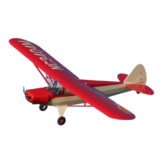
- Page 1 1/4 scale Piper PA-12 “Super Cruiser” ARF Wingspan: 106 in. (2700mm) Length: 67 in. (1700mm) Wing Area: 1581 in². (102dm²) Weight (w/o battery): 12.7 lb. (5.8kg) Weight (w/ PQ6000-8S): 15.5 lb. (7.0kg)
- Page 3 Hobby-Lobby.com is pleased to announce the 1/4 scale Piper PA-12 “Super Cruiser” as part of its Pilot-1 Golden Age Civilian Series. The Pilot-1 “Super Cruiser” encompasses the same attributes in quality construction and handling that made the original a great design.
- Page 4 Introduction & History “The end of World War II saw the resumption of private aircraft manufacture and the Piper Aircraft Company, already well known for the J-3 Cub and the J-5 Cruiser, began production of improved models of these aircraft. These were the Piper PA-11 Cub Special and the Piper PA-12 Super Cruiser.
- Page 5 Before starting, use the contents list to take an inventory and make sure it is complete. If any parts are missing or are not of acceptable quality, contact Hobby-Lobby.com support at 1-866-WE-FLY-RC (1-866-933-5972) Contents List Fuselage Battery Hatch ...
- Page 6 It does assume that this is not your first airplane. If you need assistance, please ask a local flyer, visit www.rcgroups.com, or call us here at Hobby-Lobby.com. Let’s start by installing the aileron servos. Arrange the servo as shown. Make sure the servo arm is in the center of the slot.
- Page 7 5. Use masking tape to secure the aileron servo extension wire to the pull thread plywood block. 6. Use needle nose pliers to break pull thread loose from the end of the wing. Pull aileron extension wire through wing. 7. Install each aileron servo cover with four (4) small sheet metal screws.
- Page 8 9. Insert CA hinges and aileron into wing. Make sure alignment is good with even spaces at each end of aileron. 10. With aileron deflected downward and fitted with no gap between the leading edge of aileron and wing, CA each hinge. Use thin CA, 2-3 drops per hinge, per side.
- Page 9 13. Using the line drawn in the step above, measure 6mm (1/4”) from the beveled leading edge of the aileron and mark with pen. 14. Use a 3mm (1/8”) drill bit to drill hole completely through aileron. Be careful to keep drill straight and true.
- Page 10 17. Adjust clevis to correct length and connect to aileron horn. Slide fuel tubing safety onto clevis to prevent accidental disconnect. Tighten locknut. 18. Now prepare the Elevator pushrod system for installation. Here are the parts you will need for the next few steps. 19.
- Page 11 21. Temporarily install the vertical stabilizer. Do not glue anything in the next several steps. Insert horizontal stabilizer into slot. Measure each side of the horizontal stabilizer to make sure it is centered. You can also see the structure through the covering to help you align.
- Page 12 25. Use rubbing alcohol and a paper towel to remove the marks. Insert the horizontal into the slot. Repeat the measurements in steps 21 & 22. 26. Use thin CA to glue horizontal stabilizer to the fuselage. Make sure to glue all four (4) joints thoroughly.
- Page 13 29. Repeat the technique used with the horizontal stabilizer with the vertical stabilizer shown here. Use pen to mark covering, remove covering 1/8” (3mm) inside line with soldering iron, and remove marks with alcohol or fingernail polish remover. 30. Now it is ready for installation. 31.
- Page 14 33. Install rudder and check for alignment. Deflect rudder over to side and use 2-3 drops of thin CA, per hinge, per side. 34. Insert rudder and elevator servos as shown. Note the position of the horns with the servos in their neutral position. 35.
- Page 15 37. Pull rudder cable straight. Mark where rudder horn will go with pen. 38. Drill hole through rudder. Insert rudder control horn as shown. The opposite side is identical. Use blue thread lock to secure horn in place. 39. Attach clevis, fuel tubing safety, lock nut, and treaded coupler to rudder control horn.
- Page 16 41. Install four (4) aluminum straps and eight (8) sheet metal screws on each corner of landing gear wire as shown. 42. Install wheels, wheel collars, and hubcaps. We used UHUpor contact cement to glue hubcaps in place. You could also use canopy glue.
- Page 17 45. Use a clevis and threaded adapter on the vertical stabilizer. Double loop the wire and compress crimp with pliers. Use thin CA on crimp. Complete the remaining three (3) wires in using the same technique. Alternate method: You may wish to leave the clevis off and attach exactly like the previous step.
- Page 18 49. Install motor. 50. Attach the ESC to the motor box with sheet metal screws. Route wires as necessary to receiver and battery. It is necessary to reverse two of the motor wires in this application. Black-Yellow, Red-Red- Yellow- Black. 51.
- Page 19 53. Drill a 1mm (1/32”) pilot hole through the paper strip, cowl, and wood mounting blocks for each of the four (4) screws. 54. Fold paper strips out of the way and slightly enlarge the hole in the fiberglass cowl only! This is done to keep cowl from cracking when inserting the cowl sheet metal screws.
- Page 20 57. This is looking in through the battery hatch (airplane is upside down). Install the Duralite Receiver regulator with switch. The Deans Ultra connector for the receiver LiPo is shown on the right side of the photo. 58. Install Velcro strips and straps for holding the two “6000-4S”...
- Page 21 61. You may wish to install a black dash and instrument panel. Use the templates at the back of this manual to fabricate them. We used dark grey 600-grit wet/dry sandpaper for our prototype. Trial fit the windshield to make sure dash doesn’t show around edges.
- Page 22 65. Pull the wing tubes out until you can see the holes drilled in the previous step. Use a 3/32” (2.5mm) drill bit to enlarge the holes in both wing tube joiners. 66. Insert both aluminum joiner tubes fully into the wing panel.
- Page 23 69. Prepare the wing struts for assembly. The front strut is slightly larger than the rear strut. 70. This photo shows how the jury struts will be installed with fiberglass covers. Note how the covers align with the aluminum brackets underneath.
- Page 24 73. Install the jury struts with machine screws. Use UHUpor or canopy glue to glue the fiberglass covers in place. If you plan on removing the struts, glue covers only to the jury struts and not the wing. You may need to enlarge the holes in the covers for access to the screws.
- Page 25 77. Please refer to your radio manual for the following few steps. Please note that some computer radios have separate settings for exponential for high and low rate positions. Make sure you double check all settings before flight. If you are new to programming, check with a local experienced modeler or hobby shop for assistance.
- Page 26 81. Adjust Rudder LOW RATE travel to get 1-3/8” (35mm or 15º) LEFT and 1-3/8" (35mm or 15º) RIGHT. Use 30% expo to soften the center travel per your radio manual. (JR/Spektrum +30% and Futaba/Hitec -30%). 35mm 35mm 82. Adjust each aileron’s HIGH RATE travel to get 7/8”...
- Page 27 85. Alternate Tail Brace instructions. You may wish to create a more scale tail brace system for your PA-12. These parts are not included in the kit but are easy to fabricate. Dubro sells a tail brace kit (Dubro p/n 205) that is very similar to this if you wish to purchase something a little more ready made.
- Page 28 89. When all braces are complete, install with machine screws, nuts, and blue thread lock glue. You are now finished! Now go fly and enjoy your new Hobby-Lobby “Pilot-1 Piper PA-12 Cub Super Cruiser”!
- Page 29 Warranty Hobby-Lobby guarantees this kit to be free from defects in both material and workmanship at the date of purchase. This warranty does not cover any component parts damaged by use or modification. In no event shall Hobby-Lobby’s liability exceed the original cost of the purchased kit.
- Page 30 Instrument Panel Template Dash Cover Template...
-
Page 32: Radio Control
2008 Official Academy of Model Aeronautics National Model Aircraft Safety Code GENERAL 1. A model aircraft shall be defined as a non-human-carrying device capable of sustained flight in the atmosphere. It shall not exceed limitations established in this code and is intended to be used exclusively for recreational or competition activity. - Page 33 allocation of frequencies for each site, a day-use agreement between sites, or testing which determines that no interference exists. A frequency-management agreement may exist between two or more AMA chartered clubs, AMA clubs and individual AMA members, or individual AMA members.
- Page 34 Hobby Lobby International, Inc. 5614 Franklin Pike Circle Brentwood, TN 37027 1-866-WE-FLY-RC (1-866-933-5972) www.hobby-lobby.com...
Need help?
Do you have a question about the Pilot-1 and is the answer not in the manual?
Questions and answers