
Related Manuals for Hobby-Lobby Piper PA-12 Super Cruiser


Summary of Contents for Hobby-Lobby Piper PA-12 Super Cruiser
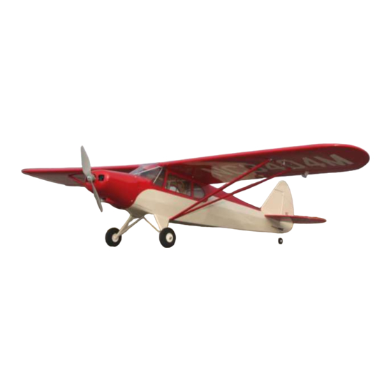
- Page 1 1/8 scale Piper PA-12 “Super Cruiser” ARF Wingspan: 53.25 in. (1353mm) Length: 39.5 in. (1003mm) Wing Area: 360 in². (23.23dm²) Weight (w/o battery): 27.5 oz. (780g) Weight (w/ TP2100-3S): 34 oz. (964g)
- Page 3 Hobby-Lobby.com is pleased to announce the 1/8 scale Piper PA-12 “Super Cruiser” as part of its Pilot-1 Golden Age Civilian Series. The Pilot-1 “Super Cruiser” encompasses the same attributes in quality construction and handling that made the original a great design.
- Page 4 These were the Piper PA-11 Cub Special and the Piper PA-12 Super Cruiser. Walter Jamoneau, who was head of the engineering department at Piper for many years, modified the J-5 into the PA-12. Test flights were made in December 1945, and the first production version of the aircraft appeared in February 1946.”...
- Page 5 Before starting, use the contents list to take an inventory and make sure it is complete. If any parts are missing or are not of acceptable quality, contact Hobby-Lobby.com support at 1-866-WE-FLY-RC (1-866-933-5972) Contents List Fuselage Battery Hatch ...
- Page 6 It does assume that this is not your first airplane. If you need assistance, please ask a local flyer, visit www.rcgroups.com, or call us here at Hobby-Lobby.com. Let’s start by preparing the aileron servos and aileron wire extensions. Wrap the connection with tape or use heat shrink tubing to prevent an accidental disconnect.
- Page 7 5. Insert the elevator or rudder pushrod into the wing so that it sticks out of the aileron servo cavity as shown. Note: Be careful not to bend pushrod. 6. Tape the aileron wire extension to the end of the pushrod. Pull pushrod and wire through wing panel.
- Page 8 9. Insert CA hinges and aileron into wing. Make sure alignment is good with even spaces at each end of aileron. 10. With aileron deflected downward and fitted with no gap between the leading edge of aileron and wing, CA each hinge. Use thin CA, 2 drops per hinge per side.
- Page 9 13. Use straight edge and pen to mark where the aileron control horn will be attached. 14. Make another mark 8mm (5/16”) as shown. This is where the aileron horn pins will go through the balsa aileron block. 15. Temporarily insert aileron control horn into aileron.
- Page 10 17. Insert horn and use thin CA or 5-min epoxy to glue in place. Repeat steps 1-17 for opposite wing panel. 18. Insert aileron pushrod “z-bend” into outer hole of servo arm as shown. You may need to use a drill bit, reamer, or hobby knife to enlarge hole in servo arm.
- Page 11 21. Using the same technique as the ailerons to install the elevator. Pre-bend the CA hinges, deflect downwards, CA each hinge 2 drops per side. *Note: before gluing, if you feel hinges are too stiff, cut each hinge in half so that they are 1/4” wide by 1/2" long. Then glue normally.
- Page 12 25. When completely satisfied with fit and alignment, use thin CA to glue each joint thoroughly. There are six joints total. 26. Remove covering from lower front of rudder. Insert and glue tailwheel wire into predrilled hole. Use 5-min epoxy for this step.
- Page 13 29. Install pushrods and servos as shown. Make sure servos are centered before installing horns. The outer holes may need to be drilled out slightly for the “z-bend” in the wire. 30. Install pushrod clevis to the rudder and elevator pushrods. Use a sheet metal screw to install tailwheel bracket.
- Page 14 33. Using the indentations, drill two pilot holes through elevator. The drill bit should be smaller than the control horn pin diameter, approximately 1.5mm (1/16”). 34. Trace around horn, remove the covering, install control horn flush. 35. Use thin CA on both sides of elevator to secure horn in place.
- Page 15 37. Install four (4) aluminum straps and eight (8) sheet metal screws on each corner of landing gear wire as shown. Install wheels and wheel collars. 38. Solder motor to speed control. In our application, on the motor side of the ESC, connect black to yellow, red to red, yellow to black.
- Page 16 41. Cut four (4) strips of paper the same width of cowling blocks (approx. 1/2” wide) and 4” long. Use tape to install paper strips over each cowling block as shown. 42. Install cowling. Make sure the paper strips are on outside of cowl. Align cowl with propeller shaft face 5mm (3/16”) in front of cowl.
- Page 17 45. Fold paper strips out of the way and slightly enlarge the hole in the fiberglass cowl only! Here we are using a reamer but you could use a hobby knife or drill bit. This is done to keep cowl from cracking when inserting the cowl sheet metal screws.
- Page 18 49. Use canopy glue or craft glue to install side windows. 50. Use canopy glue to install windshield. Use a wet paper towel to clean up any mess before glue dries. Use masking tape to hold everything in place while the glue dries. 51.
- Page 19 53. The tail brace cable should look like this when complete. 54. Prepare the wing struts for assembly. The front strut is slightly larger than the rear strut. 55. Place scrap foam or towel under center section of wing for support. You do not want any load placed on wing tips while installing struts.
- Page 20 57. When you are satisfied with the straightness of the wing, use a sheet metal screw to attach the forward wing strut at 1- 5/8” (41mm) from the Leading Edge of the wing. 58. Install a sheet metal screw in the rear strut at 5-3/8”...
- Page 21 61. Please refer to your radio manual for the following few steps. Please note that some computer radios have separate settings for exponential for high and low rate positions. Make sure you double check all settings before flight. If you are new to programming, check with a local experienced modeler or hobby shop for assistance.
- Page 22 65. Adjust Rudder LOW RATE travel to get 9/16” (15mm) LEFT and 9/16" (15mm) RIGHT. Use 20% expo to soften the center travel per your radio manual. (JR/Spektrum +20% and Futaba/Hitec -20%). 15mm 15mm 66. Adjust each aileron’s HIGH RATE travel to get 9/16”...
- Page 23 Warranty Hobby-Lobby guarantees this kit to be free from defects in both material and workmanship at the date of purchase. This warranty does not cover any component parts damaged by use or modification. In no event shall Hobby-Lobby’s liability exceed the original cost of the purchased kit.
-
Page 26: Radio Control
2008 Official Academy of Model Aeronautics National Model Aircraft Safety Code GENERAL 1. A model aircraft shall be defined as a non-human-carrying device capable of sustained flight in the atmosphere. It shall not exceed limitations established in this code and is intended to be used exclusively for recreational or competition activity. - Page 27 allocation of frequencies for each site, a day-use agreement between sites, or testing which determines that no interference exists. A frequency-management agreement may exist between two or more AMA chartered clubs, AMA clubs and individual AMA members, or individual AMA members.
- Page 28 Hobby Lobby International, Inc. 5614 Franklin Pike Circle Brentwood, TN 37027 1-866-WE-FLY-RC (1-866-933-5972) www.hobby-lobby.com...
Need help?
Do you have a question about the Piper PA-12 Super Cruiser and is the answer not in the manual?
Questions and answers