Advertisement
Quick Links
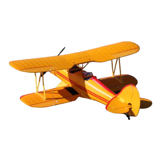
Hobby Lobby's "Waco Biplane RTF"
Wingspan:
Length:
Wing Area:
Flying Weight:
Radio controlled model aircraft are capable of inflicting serious injury and/or property damage if not assembled, operated, and
maintained in a competent and safe manner. If you are not already experienced with radio controlled models, we strongly suggest
Hobby-Lobby guarantees this kit to be free from defects in both material and workmanship at the date of purchase. This warranty
does not cover any component parts damaged by use or modification. In no event shall Hobby-Lobby's liability exceed the original
39 in.
31 in.
503 in².
24 oz.
WARNING – THIS IS NOT A TOY!
that you find an experienced modeler to assist you.
Warranty
cost of the purchased kit.
Completely read through this manual before starting construction.
1
Advertisement

Related Manuals for Hobby-Lobby ESM1100


Summary of Contents for Hobby-Lobby ESM1100
- Page 1 Hobby Lobby's “Waco Biplane RTF” Wingspan: 39 in. Length: 31 in. Wing Area: 503 in². Flying Weight: 24 oz. WARNING – THIS IS NOT A TOY! Radio controlled model aircraft are capable of inflicting serious injury and/or property damage if not assembled, operated, and maintained in a competent and safe manner.
- Page 2 Before starting, use the Contents list to take an inventory and make sure it is complete. If any parts are missing or are not of acceptable quality, contact Hobby-Lobby Support at 1-866-WE-FLY-RC (1-866-933-5972) Contents List ¨ Pre-painted Fuselage (molded foam) ¨...
- Page 3 1. Lay out screws is size order groups. 2. Two-12mm long screws for prop assembly 3. Twelve-8mm long screws for fuselage cabanes, horizontal tail, vertical tail 4. Eight-5mm long screws for outer wing “N- struts” 5. Two-5mm screws for spinner. 6.
- Page 4 9. Peel the backing paper off the double stick tape on the rear of the fuselage. 10. Position the tailplane so that the 2 mounting screws line up through the horizontal tail. Screw in place through bracket with 2-8mm screws. 11.
- Page 5 14. The “N” struts mount using the 5mm long screws 15. Please note each “N” strut is labeled with Up and Down to make it easier to locate and install. The struts are screwed in place on the fuselage side of the strut brackets.
- Page 6 18. Screw fuselage cabane struts into position using 8mm long screws. 19. Cabane struts mounted and awaiting the installation of the upper wing panel 20. The receiver is pre-installed and pre- connected to the elevator and rudder servos. The open extension is for the ailerons.
- Page 7 22. Place the lower wing into position on the fuselage making sure to not pinch any wires in the wing saddle. 23. The wing mounting screws are 40mm and 60mm long. 24. Use the 40mm long screw at the rear of the wing and the 60mm screw at the front of the wing.
- Page 8 26. Screw the upper end of each “N” strut into position using the 5mm long screws. 27. Connect the bottom of the aileron inter- connector pushrod as shown in the photo. 28. Attach the clevis end to the upper aileron. You may need to adjust the length of the pushrod so that both of the ailerons are in neutral position at the same time.
- Page 9 30. Snap the plastic landing gear fairing into position on the wire landing gear. 31. Slip the charged battery into position through the battery hatch. Slide the battery forward in the battery slot. 32. View of the battery access with the flight battery installed.
- Page 10 34. Locate the prop hub and prop blades 35. Prop assembly is secured by 2-12mm long screws 36. Place front of hub (the part with the internal posts) face down on the bench. Fit each prop blade onto the posts. The larger hole is on the front side of the blade.
- Page 11 39. The ply disc is next. 40. Then add the transparent plastic spinner mount followed by the metal washer and nut. Tighten the nut using a wrench or pliers. 41. While tightening the mounting nut make sure to orient the small holes on the sides of the transparent part at 90 degrees to the prop blade orientation.
- Page 12 44. Screw spinner into position, do not overtighten. 45. With the supplied components installed the C.G. (center of gravity) is automatically correct. 46. The CG is measured from the leading edge of the upper wing. It is set at approx. 3”...
- Page 13 52. Ailerons= 1/2" Up and Down 53. Rudder= 1-1/8" Each Way Hobby Lobby International, Inc. 5614 Franklin Pike Circle Brentwood, TN 37027 1-866-WE-FLY-RC (1-866-933-5972) www.hobby-lobby.com PEL4107 V2 Instruction Manual.doc 6/10 mgh...
Need help?
Do you have a question about the ESM1100 and is the answer not in the manual?
Questions and answers