Table of Contents
Advertisement
Advertisement
Table of Contents

Related Manuals for prowarm protouch iQ


Summary of Contents for prowarm protouch iQ
-
Page 2: Table Of Contents
Room Thermostat? 23-26 Optional Features Installation Procedure Re-calibrating the Thermostat Mode Select Error Codes Pairing the ProTouch iQ Hub Thermostat Mode Wiring Diagram Pairing the ProTouch iQ Mode 2 - Time Clock What is a Mesh Network? LCD Display 29-30... -
Page 3: What Is A Programmable Room Thermostat
What is a Programmable Room Thermostat? A programmable room thermostat is both a programmer and a room thermostat. The way to set and use your programmable room thermostat is to find the lowest temperature settings that you are comfortable with at the different times you have A programmer allows you to set “On”... -
Page 4: Installation Procedure
Do not push hard on the LCD screen as this may cause irreparable damage. This ProTouch iQ is designed to be flush mounted and requires a back box of 35mm (minimum depth) to be sunk into the wall prior to installation. -
Page 5: Mode Select
• Press the Tick key to confirm selection ............. The next step is to join the ProTouch iQ to the ProTouch iQ Hub, we recommend joining the ProTouch iQ located nearest to the ProTouch iQ Hub first. The ProTouch iQ will revert to the main display screen for the selected mode. -
Page 6: What Is A Mesh Network
• Feature 01 is displayed on screen. Mode 1 - Thermostat • Press the Tick key to pair the ProTouch iQ to the ProTouch iQ Hub ....• The MESH symbol appears flashing on the display. • When the ProTouch iQ successfully connects to the ProTouch iQ Hub the MESH symbol will be permanently displayed. -
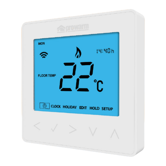
Page 7: Lcd Display
LCD Display Day Indicator - Displays the day of the week. Mesh Symbol – Displayed when connected to the ProTouch iQ Hub. Floor Limit Symbol – Displayed when the floor probe has reached the temperature limit set on feature 07. -
Page 8: Temperature Display
Hours Minutes When the ProTouch iQ is set to use both the air & the floor sensor, the room temperature will be displayed by default. To view the current floor temperature, press and hold the Left and Right arrow keys... -
Page 9: Comfort Levels Explained
Comfort Levels Explained The ProTouch iQ offers three program mode options; Weekday/Weekend programming, • Use the Up / Down keys to set the hours .............. 7 Day programming and 24 Hour programming. There is also the option to • Press Tick to confirm ...................... -
Page 10: Temperature Control
Temperature Control Temperature Hold The Up / Down keys allow you to adjust the set temperature ......The temperature hold function allows you to manually override the current operating program and set a different temperature for a desired period. When you press either key, you will see the word SET and the desired •... -
Page 11: Locking/Unlocking The Protouch Iq
The display will show 00:00 and you will need to enter a four digit pin number. In this mode, the ProTouch iQ will display the frost icon and will only turn the heating ON should the room temperature drop below the set frost temperature (see page 23). -
Page 12: Power On/Off
ProTouch iQ remains active. The thermostat will maintain this temperature for the duration of the holiday and will To turn the ProTouch iQ off completely, scroll to the Power Icon and hold then automatically return to the program mode on your return. -
Page 13: Optional Features Explained
Feature 01 – Pairing To ProTouch iQ Hub: This function is used to connect the thermostat the building is warm at the programmed time. The thermostat uses the rate of to the ProTouch iQ Hub. -
Page 14: Adjusting The Optional Settings
Adjusting the Optional Settings Optional Settings - Feature Table FEATURE DESCRIPTION SETTING • Use the Left / Right keys to select SETUP .............. • Press Tick to confirm selection .................. Pairing Used to add zone to the neoHub Switching Differential 00 = 0.5 01 = 1.0 C (Default) -
Page 15: Re-Calibrating The Thermostat
Wiring Diagram - ProTouch iQ Re-calibrating the Thermostat If you need to re-calibrate the thermostat, follow these steps. TC-EM MAINS SUPPLY • Use the Left / Right keys to scroll to the Power Icon ......• Press and hold Tick to turn the display OFF ............ -
Page 16: Mode 2 - Time Clock
LCD Display Day Indicator - Displays the day of the week. Mesh Symbol – Displayed when connected to the ProTouch iQ Hub. Key Lock Indicator – Displayed when the KeyLock is Locked. Set – Displayed when changes are being made to the program schedule or current set point. -
Page 17: Setting The Switching Times
Factory Reset Setting the Switching Times To reset the device to factory default settings, follow these steps: To program the switching times, follow these steps. • Use the Left / Right keys to scroll to SETUP ............• Use the Left / Right keys to scroll to EDIT and press Tick ......... •... -
Page 18: Timer Override
Optional Features Explained Timer Override To override the current timed output ON/OFF follow these steps. Feature 01 – Pairing To ProTouch iQ Hub: This function is used to connect the time clock to the ProTouch iQ Hub. • Use the Left / Right keys to scroll to HOLD and press Tick ....... -
Page 19: Wiring Diagram
Notes Wiring Diagram - Time Clock Mode ..................................MAINS SUPPLY ..................................230VAC ......................................................................................................LOAD ........................................................................................................................................16 AMP MAX LOAD ......................................................................................................This product must only be installed by a qualified electrician and comply with local installation regulations.................................. - Page 20 Notes Notes ................................................................................................................................................................................................................................................................................................................................................................................................................................................................................................................................................................................................................................................................................................................................................................................................................................................................................................................
- Page 21 www.prowarm.com...
Need help?
Do you have a question about the protouch iQ and is the answer not in the manual?
Questions and answers