Table of Contents
Advertisement
Advertisement
Table of Contents

Related Manuals for prowarm ProDigital


Summary of Contents for prowarm ProDigital
- Page 1 ™...
-
Page 2: Product Image
Model: ProDigital™ Electric Floor Model... -
Page 3: Table Of Contents
Table of Contents Product Image Adjusting the Optional Settings Recalibrating the Edge Table of Contents Error Codes What is a Programmable Room Thermostat? Wiring Diagram Installation Procedure Mode Select Mode 1 - Thermostat Mode 2 - Time Clock LCD Display 9-10 28-29 LCD Display... -
Page 4: What Is A Programmable
What is a Programmable Room Thermostat? Section Header A programmable room thermostat is both a programmer and a room thermostat. A programmer allows you to set “On” and “Off” periods to suit your own lifestyle. A room thermostat works by sensing the air temperature, switching on the heating when the air temperature falls below the thermostat setting, and switching it off once this set temperature has been reached. - Page 5 Section Header The way to set and use your programmable room thermostat is to find the lowest temperature settings that you are comfortable with at the different times you have chosen, and then leave it alone to do its job. The best way to do this is to set the room thermostat to a low temperature –...
-
Page 6: Installation Procedure
Installation Procedure Section Header Mount the thermostat at eye level. Read the instructions fully so you get the best from our product. Don’t Do not install near to a direct heat source as this will affect functionality. Do not push hard on the LCD screen as this may cause irreparable damage. This thermostat is designed to be flush mounted and requires a back box of 35mm (minimum depth) to be sunk into the wall prior to installation. - Page 7 Section Header Model:...
-
Page 8: Mode Select
Mode Select Section Header ProDigital™ can either be used as a thermostat or a time clock. Thermostat mode is the default setting. To change between thermostat & time clock modes, follow these steps. then press and hold • Use the ‘Left/Right’ arrow keys to highlight the button for 3 seconds .................. -
Page 9: Mode 1 - Thermostat
Mode 1 - Thermostat Section Header Model:... -
Page 10: Lcd Display
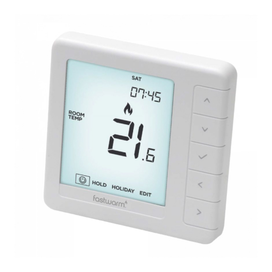
LCD Display Section Header Electric Floor Model... - Page 11 LCD Display Section Header 1. Day Indicator - Displays the day of the week. 2. Flame Symbol – Displayed when the thermostat is calling for heat and flashes when optimum start is active. 3. Clock - Time displayed in 24 hour format. 4.
-
Page 12: Power On/Off
Power On/Off Section Header The heating is indicated ON when the flame icon is displayed. When the Flame Icon is absent, there is no requirement for heating to achieve the set temperature but the thermostat remains active. To turn the thermostat off completely, scroll to the Power Icon and hold the key for approximately 3 seconds until the display goes blank ...... -
Page 13: Setting The Time & Date
Setting the Time and Date Section Header To set the clock, follow these steps. then press and hold the • Use the ‘Left/Right’ arrow keys to highlight button for 3 seconds ........................At this point the screen will go blank showing only ‘SETUP’ and ‘CLOCK’ . •... -
Page 14: Temperature Display
Room Temperature Floor Temperature When the ProDigital™ is set to use both the air & the floor sensor, the room temperature will be displayed by default. To view the current floor temperature, press and hold the Left and Right arrow keys for 5 seconds, the floor temperature will then be displayed ........ -
Page 15: Edit Comfort Levels
Section Header The ProDigital™ offers three program mode options; Weekday/Weekend, 7 Day and 24 Hour programming. There is also the option to use the ProDigital™ as a manual thermostat. The thermostat is supplied with comfort levels already factory programmed, but these can be changed easily. - Page 16 Section Header • Use the ‘Up/Down’ keys to set the ‘Hours’ ..................• Press to confirm ............................• Use the ‘Up/Down’ keys to set the ‘Minutes’ ................. • Press to confirm ............................• Use the ‘Up/Down’ keys to set the temperature ................. •...
-
Page 17: Temperature Control
Temperature Control Section Header The ‘Up/Down’ keys allow you to adjust the set temperature ........When you press either key, you will see the word ‘SET’ and the desired temperature value. Use the ‘Up/Down’ keys to adjust the ‘SET’ value ....... Press to confirm settings and return to the main display .......... -
Page 18: Temperature Hold
Temperature Hold Section Header The temperature hold function allows you to manually override the current operating program and set a different temperature for a desired period. • Use the ‘Left/Right’ keys to scroll to ‘Hold’ and press ..........• Repeatedly tap the ‘Up/Down’ keys to set the desired ‘Hold’ time (Hours) then press ........................ -
Page 19: Frost Protection
Frost Protection Frost Protection Section Header Use the ‘Left/Right’ keys to scroll to the ‘Power Icon’ ........... Use the ‘Left / Right’ keys to scroll to the ‘Power Icon’ ............. The frost icon will toggle ON/OFF each time is pressed ............The frost icon will toggle ON/OFF each time is pressed ............ -
Page 20: Locking/Unlocking The Thermostat
Locking the Thermostat Section Header The ProDigital™ has a keypad lock facility. To activate the lock follow these steps. • Use the ‘Left/Right’ keys to scroll to Hold & press for 7 seconds ......The display will show 0000. At this point enter a four digit pin number. -
Page 21: Holiday
In thermostat mode; the holiday function reduces the set temperature in your home to the frost mode temperature setting that is configured in the setup menu. The ProDigital™ will maintain this temperature for the duration of the holiday and will then automatically return to the program mode on your return. -
Page 22: Optional Settings Explained
Optional Settings Explained Section Header THE FOLLOWING SETTINGS ARE OPTIONAL AND IN MOST CASES NEED NOT BE ADJUSTED. Temperature Format: This function allows you to select between °C and °F. Switching Differential: This function allows you to increase the switching differential of the thermostat. - Page 23 Floor Temp Limit: When the Floor Sensor has been enabled in feature 05, you can set a Section Header floor limiting temperature between 20-45°C, this protects the floor from overheating. (27°C is the default). Note: ‘Air Sensor Only’ MUST NOT be used to control electric underfloor heating. Floor Sensor or Both should be used.
-
Page 24: Optional Settings - Feature Table
Optional Settings - Feature Table Section Header FEATURE DESCRIPTION SETTING Temperature Format 00 = °C, 01 = °F (00 = Default) Switching Differential 00 = 0.5°C, 01 = 1.0°C (Default) 02 = 2.0°C, 03 = 3.0°C Output Delay 00 - 15 Minutes (00 = Default) Up/Down Temperature Limit 00°... -
Page 25: Adjusting The Optional Settings
Adjusting the Optional Settings Adjusting the Optional Settings Section Header Use the ‘Left/Right’ arrow keys to highlight then press and hold the • Use the ‘Left/Right’ arrow keys to highlight then press and hold the button for 3 seconds ....................button for 3 seconds ..................... -
Page 26: Recalibrating The Edge
‘ON’ ..........Error Codes The ProDigital™ will display an error code if there is a fault with the temperature sensor, these error codes are explained below. E0 = The internal sensor has developed a fault. -
Page 27: Wiring Diagram
Wiring Diagram - ProDigital™ Section Header Model: ProDigital ™ 230VAC MAINS SUPPLY Floor Not used. Sensor LOAD FLOOR PROBE MATTING OR WIRE - 16 AMP MAX This product must only be installed by a qualified electrician and comply with local installation regulations. -
Page 28: Mode 2 - Time Clock
Mode 2 - Time Clock Section Header Electric Floor Model... - Page 29 Section Header Model: Model: HM-01-16A...
-
Page 30: Lcd Display
LCD Display Section Header 1. Day Indicator - Displays the day of the week. 2. Clock - Time displayed in 24 hour format. 3. Until & Hold Left - ‘Until’ displayed during a timer override. ‘Hold Left’ appears when a temperature hold is active, plus the remaining time will be shown. -
Page 31: Setting The Switching Times
Setting the Switching Times Section Header To program the switching times, follow these steps. • Use the ‘Left/Right’ keys to scroll to ‘EDIT’ ............• Press to confirm selection ..................... • Use the ‘Left/Right’ keys to select the day/period to program ....•... -
Page 32: Timer Override
Timer Override Section Header To override the timed output ‘ON/OFF’ , follow these steps......... • Use the ‘Left/Right’ keys to highlight ‘HOLD’ then press ........• Use the ‘Up/Down’ keys to set the hours then press ........• Use the ‘Up/Down’ keys to set the minutes then press •... -
Page 33: Optional Settings Explained
Optional Settings Explained Section Header Programming Mode: The following program modes are available; 5/2 Day Programming - 4 On/Off switching times for the weekdays and 4 On/Off switching times for the weekend. 7 Day Programming - 4 individual On/Off switching times for each day. 24 Hours - 4 On/Off switching times over a 24 hour period. -
Page 34: Adjusting The Optional Settings
Adjusting the Optional Settings Adjusting the Optional Settings Section Header Use the ‘Left/Right’ arrow keys to highlight then press and hold the • Use the ‘Left/Right’ arrow keys to highlight then press and hold the button for 3 seconds ....................button for 3 seconds ..................... -
Page 35: Wiring Diagramm - Time Clock Mode
Wiring Diagram - Time Clock Mode Section Header Model: ProDigital ™ 230VAC MAINS SUPPLY Floor Not used. Sensor LOAD LOAD 16 AMP MAX This product must only be installed by a qualified electrician and comply with local installation regulations. Model:... - Page 36 Notes ........................................................................................................................................................................................................................................................................................................................................................................................................................................................Electric Floor Model...
- Page 37 Notes ........................................................................................................................................................................................................................................................................................................................................................................................................................................................Model:...
- Page 38 Notes ........................................................................................................................................................................................................................................................................................................................................................................................................................................................Electric Floor Model...
- Page 39 Notes ........................................................................................................................................................................................................................................................................................................................................................................................................................................................Model:...
- Page 40 Model: www.prowarm.com Rev 1.0...
Need help?
Do you have a question about the ProDigital and is the answer not in the manual?
Questions and answers