Power One AURORA Installation And Operator's Manual
Photovoltaic inverters
Hide thumbs
Also See for AURORA:
- Installation manual (11 pages) ,
- Installation and operation manual (104 pages)

Related Manuals for Power One AURORA


Summary of Contents for Power One AURORA
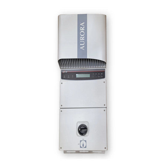
- Page 1 ® AURORA Photovoltaic Inverters INSTALLATION AND OPERATOR’S MANUAL Model number: PVI-2000-OUTD-AU Rev. 1.0...
-
Page 2: Save These Instructions
Installation and operator’s manual Page 2 of 65 PVI-2000-OUTD-AU Rev.: 1.0) REVISION TABLE Document Author Date Change description Revision Gianluca 27/10/2008 First release of the document Pieralli SAVE THESE INSTRUCTIONS! IMPORTANT SAFETY INSTRUCTIONS POWER-ONE: Reproduction and disclosure, even partially, of the contents of this manual are strictly forbidden without prior authorization of Power- One. - Page 3 Installation and operator’s manual Page 3 of 65 PVI-2000-OUTD-AU Rev.: 1.0) IMPORTANT SAFETY INSTRUCTIONS This manual contains important safety and operational instructions that must be accurately understood and followed during the installation and maintenance of the equipment. To reduce the risk of electrical shock hazards, and to make sure the equipment is safely installed and commissioned, special safety symbols are used in this manual to highlight potential safety risks and important safety information.
- Page 4 PVI-2000-OUTD-AU Rev.: 1.0) USEFUL INFORMATION ON SAFETY STANDARDS FOREWORD The installation of AURORA must be performed in full compliance with national and local standards and regulations. AURORA has no internal user serviceable parts other than fuses. For any maintenance or repair please contact the nearest authorized repair centre.
- Page 5 Electrical parts must not be mechanically damaged or destroyed (potential health risk). ELECTRICAL CONNECTION The Aurora inverter should be installed incompliance with all prevailing local and national regulations Electrical connections shall be carried out in accordance with the applicable regulations, such as conductor sizing, over-current protection devices and grounding connection.
- Page 6 Installation and operator’s manual Page 6 of 65 PVI-2000-OUTD-AU Rev.: 1.0) OPERATION Systems with inverters shall be installed in accordance with applicable electrical safety and personnel safety requirements. After the inverter has been disconnected from the both input power and output power connections allow the internal capacitors to discharge before working on the equipment Comply with all corresponding marks and symbols present on each device.
- Page 7 Installation and operator’s manual Page 7 of 65 PVI-2000-OUTD-AU Rev.: 1.0) PVI-2000-OUTD-AU This document applies to the above-mentioned inverters, only Fig.1 Product label The identification plate present on the inverter includes the following data: 1) Manufacturer Part Number 2) Model Number 3) Serial Number 4) Production Week/Year...
-
Page 8: Table Of Contents
PHOTOVOLTAIC ENERGY ..........10 SYSTEM DESCRIPTION............11 PV S : “STRINGS LEMENTS OF A YSTEM ARRAYS” ..................12 .......... 14 ATA TRANSMISSION AND CHECK AURORA T ........14 ECHNICAL ESCRIPTION ............. 16 ROTECTIVE DEVICES 2.4.1 Anti-Islanding ..............16 2.4.2 Panel Ground Fault............16 2.4.3... - Page 9 Installation and operator’s manual Page 9 of 65 PVI-2000-OUTD-AU Rev.: 1.0) LCD D .................43 ISPLAY DATA CHECK AND COMMUNICATION......49 RS-485 ...............49 SERIAL LINK ..............52 DDRESS SELECTION ..............53 ATE SETTING ............55 EASUREMENT CCURACY TROUBLESHOOTING ..............56 TECHNICAL FEATURES............58 ................58 NPUT ALUES ..............61 UTPUT ALUES ........62...
-
Page 10: Foreward
Page 10 of 65 PVI-2000-OUTD-AU Rev.: 1.0) FOREWARD This document contains a technical description of the AURORA photovoltaic inverter so as to provide the installer and user all the necessary information about installation, operation and use of AURORA. PHOTOVOLTAIC ENERGY Industrialised countries (greater energy consumers) have been experimenting with energy-saving methods and reducing pollutant levels. -
Page 11: System Description
PVI-2000-OUTD-AU Rev.: 1.0) SYSTEM DESCRIPTION AURORA is an inverter that exports energy to the electrical power distribution grid. Photovoltaic panels transform the solar radiation into electrical energy in the form of direct (Dc) current (through a photovoltaic field, also known as PV generator); In order to utilise this energy and feed it back to the distribution grid, this energy shall be turned into alternating (Ac) current. -
Page 12: Main Elements Of Apv System : "Strings And Arrays
Larger photovoltaic systems can be composed of a certain number of arrays, connected to one or more AURORA inverters. By maximizing the number of panels in series per string, the cost and complexity of the system wiring can be reduced. - Page 13 NOTE: The minimum required input voltage for start the initial grid connection sequence is 200Vdc. When Aurora is connected, it will export energy on the grid since the input range will remain between 90Vdc and 580Vdc. The total current of an array must also be within the capability limits of the inverter.
-
Page 14: Data Transmission And Check
AURORA Technical Description Figure 4 shows the AURORA block diagram. The main blocks are given by the input Dc-Dc converters (also known as “booster”) and the output inverter. Both the Dc-Dc converters and the output inverter work at high switching frequency to minimize size and weight. - Page 15 AURORA operative system communicates with the relative components to carry out data analysis. All this guarantees an optimal operation of the whole system and a very high performance in every insulation and load situation, always in compliance with the relative standards and regulations.
-
Page 16: Protective Devices
AURORA in case a ground fault is detected and indicates the ground fault condition by means of a red LED on the front panel. A terminal for the equipment grounding conductor is provided in the AURORA inverter. -
Page 17: Further Protective Devices
PVI-2000-OUTD-AU Rev.: 1.0) 2.4.3 Further Protective Devices AURORA is equipped with additional protections to guarantee safe operation under all circumstances. The protections include: Continuous monitoring of the grid voltage to ensure the frequency and voltage values are within the proper operational limits;... -
Page 18: Installation
Page 18 of 65 PVI-2000-OUTD-AU Rev.: 1.0) INSTALLATION WARNING: The electrical installation of AURORA must be made in accordance with the local and national electrical standards and regulations. WARNING: The connection of AURORA to the electrical distribution grid must be performed only after receiving authorization from the utility that operates the grid. -
Page 19: Package Check List
Save AURORA original packaging, as it will have to be used in case the equipment has to be shipped out for repairs. -
Page 20: Choosing Installation Location
Page 20 of 65 PVI-2000-OUTD-AU Rev.: 1.0) Choosing installation location The location for the installation of AURORA should be selected in accordance to the following recommendations: AURORA should be placed at a suitable height from the ground to allow easy reading of the front display. -
Page 21: Wall Mounting
Use the drawing to locate the holes on the wall. A set of standard expansion stainless steel screws is included in the package for use in mounting the AURORA to a masonry wall. In case of different materials make sure to select the proper mounting hardware. - Page 22 Fig.7, and secure the screws. Fig.7 AURORA wall mounting It is possible to mount AURORA in a tilted position. In that case the thermal dissipation will not be optimized and the unit may derate the maximum output power at ambient temperatures below 40°C (see Fig.
- Page 23 Installation and operator’s manual Page 23 of 65 PVI-2000-OUTD-AU Rev.: 1.0) Fig.8 Aurora, recommended assembling It is recommended that the unit is not placed in direct sunlight. WARNING: During operation, inverter surface can reach very high temperatures. DO NOT touch inverter surface to prevent the risk of burns.
-
Page 24: Preliminaries To Electrical Connections
WARNING: The electrical connections can be done only after securing AURORA to the wall. WARNING: The connection of AURORA to the electrical distribution grid must be performed only by skilled operators and after having received authorization from the utility that operates the grid. - Page 25 NOTE: According to the typical assembly diagram (see Fig.8) each array must be connected to Dc disconnect. An AC disconnecting mean provided with fuses or an over-current protection must be used to connect AURORA to the grid. Although the fuses are not mandatory, should you choose to use a Power-One-approved over-current protection, we recommend insetting them in the system.
- Page 26 Installation and operator’s manual Page 26 of 65 PVI-2000-OUTD-AU Rev.: 1.0) WARNING: All power wires connecting AURORA must have a section of at least 14 AWG (2.5mm ) and must be able to operate at temperature of at least 90 °C.
-
Page 27: Electrical Connections
Step 1/4: Open the Ac disconnect switch Step 2/4: Open the Dc disconnect switch Step 3/4: Connect AURORA to the Ac disconnect switch WARNING: Use proper, low impedance wires to connect AURORA to the Ac disconnect. WARNING: AURORA must be connected to the AC disconnect switch with a tripolar wire: a phase conductor, a neutral conductor and a yellow- green one for the earth connection (PE protection). - Page 28 NOTE: In case your system has an additional kW-hour metre installed between the Ac disconnect and AURORA, please apply the Ac connection procedure to the terminals of the metre. Step 4/4: Connect AURORA to the Dc disconnect switches...
-
Page 29: Access To The Terminal Blocks By Removing The Right Side Panel
Installation and operator’s manual Page 29 of 65 PVI-2000-OUTD-AU Rev.: 1.0) Access to the terminal blocks by removing the right side panel WARNING: To avoid the risk of electric shock from energy stored in capacitors. Wait 5 minutes after disconnecting both Ac and Dc connections before opening the side panel. -
Page 30: Start-Up
It’s normal that the unit produces an audible sound during the test. 4) Then the AURORA will export to the grid and the green Power LED will be continuously lit (provided there is enough solar radiation to feed power to the grid). -
Page 31: Monitoring And Data Transmission
Data transmission on a dedicated serial RS-485 line or RS-232 line. The data can be collected by a PC or data logger equipped with a suitable RS-485 or RS-232 port. In case you use the RS-485 line, a RS-485/RS-232 AURORA serial interface converter model number PVI-RS232485 can be useful. You can also use the AURORA Easy Control (*) data logger. - Page 32 Installation and operator’s manual Page 32 of 65 PVI-2000-OUTD-AU Rev.: 1.0) Fig.14 – Aurora data communication...
-
Page 33: Available Data
Real time data The real time operating data can be transmitted upon request over the communication lines and is not recorded internally by the AURORA inverter. The free AURORA Communicator interface software, provided on the installation CD can be used to retrieve and store data on a PC computer (please check on www.power-one.com... -
Page 34: Internally Logged Data
PVI-2000-OUTD-AU Rev.: 1.0) 5.2.2 Internally Logged Data AURORA stores internally the following data: Lifetime counter of grid connection time Lifetime counter of energy transferred to the grid Energy transferred to the grid every 10 seconds for the last 8640 periods of 10... -
Page 35: Led Indicators
AURORA will remain in that status until the operator presses ESC button ( 4 ) to restart the connection sequence. If AURORA does not connect and a Ground Fault is detected again technical assistance should be contacted to review... - Page 36 Installation and operator’s manual Page 36 of 65 PVI-2000-OUTD-AU Rev.: 1.0) Fig.15 LED location The following table summarize all the possible LED activation configurations related to each AURORA inverter operating status. KEY: LED on LED flashing LED off Any of the above conditions...
- Page 37 It is a transition status while yellow: settings loading and operating conditions are red: waiting for grid check checked. green: Aurora is powering the Standard machine operation yellow: grid (search of max. power point red: or constant voltage). green: System insulation device...
- Page 38 When the red LED turns on, try to reset the fault indication by pressing the multi-function ESC key at the side of the display. If AURORA reconnects to the grid, the fault was due to a transient event (such as condensation and moisture getting into the panels).
- Page 39 Page 39 of 65 PVI-2000-OUTD-AU Rev.: 1.0) 5) Malfunction/Fault indication Every time Aurora check system detects an operative malfunction or fault of the monitored system, the yellow LED comes on and a message showing the type of problem found appears on the LCD.
-
Page 40: Messages And Error Codes
Usually, when an error signal appears, an action is needed. This action will be managed as much as possible by AURORA or, in case this is not possible, AURORA will supply all the necessary information to assist the person fixing the fault on the equipment or system. -
Page 41: Pvi-2000-Outd-Au Rev.: 1.0)
Installation and operator’s manual Page 41 of 65 PVI-2000-OUTD-AU Rev.: 1.0) Alarm n. Warning Error Message Description code code Input voltage under threshold ( when Sun Low W001 OFF ) Input OC E001 Input Over current Input UV W002 Input Undervoltage Input OV E002 Input Overvoltage... - Page 42 Installation and operator’s manual Page 42 of 65 PVI-2000-OUTD-AU Rev.: 1.0) measurement ( ZGrid ) Wrong leakage current Int.Error E030 measurement (ILeak) Int.Error E031 Wrong voltage measurement V Int.Error E032 Wrong current measurement I Fan Fail W010 Defective Fan ( log only ) Int.Error E033 Internal temperature...
-
Page 43: Lcd Display
Data are shown cyclically, the screens change every 5 seconds. On the right of the display there is a button that when pressed freezes the screen. Pushing the button again unfreezes the screen. When AURORA is turned on the display shows the following screen for about 10 seconds: Initializing.. - Page 44 ### Hz Fgrid ### Hz In range Out of range! After AURORA is connected to the grid the display starts showing cyclically the following information screens, each for 5 seconds: First screen: Type and Part Number Type #### Part No. ####...
- Page 45 Installation and operator’s manual Page 45 of 65 PVI-2000-OUTD-AU Rev.: 1.0) Third screen: measured insulation resistance Riso MOhm Fourth screen: Output power and Voltage Input from the photovoltaic array ## W ## V Fifth screen: Total energy exported to the grid (E-Total) and total operating time (h-Total, that is time during which the unit was active).
- Page 46 Installation and operator’s manual Page 46 of 65 PVI-2000-OUTD-AU Rev.: 1.0) Seventh screen: Daily energy (E-Today) and mode of operation of the inverter (ModeInverter) E-Today ## Wh ModeInverter OK Eighth screen: Leakage current ( I-Leak ) I-Leak XXXXX In case the inverter is not working properly the Fault or Ground Fault LEDs will turn on as described in paragraph 5.3, and the following three screens scroll on the LCD remaining on for 5 seconds.
- Page 47 Installation and operator’s manual Page 47 of 65 PVI-2000-OUTD-AU Rev.: 1.0) The sequence of the screens is summarized in the following figure: Grid error I nitializing... Please Wait Vgrid Fgrid Out of range Out of range Vgrid Fgrid In range In range Next Connection Regular cycle...
- Page 48 E-Today Total energy exported to the grid today h-Total Total time since the unit was first operated Type Type of AURORA Serial Number Part No° Part Number Firmware Firmware release number Time during which the unit exported energy...
-
Page 49: Data Check And Communication
Installation and operator’s manual Page 49 of 65 PVI-2000-OUTD-AU Rev.: 1.0) DATA CHECK AND COMMUNICATION RS-485 serial link The RS-485 link uses two wires for signals plus a third wire for signal grounding, which is different from the equipment grounding of the unit. The wires must be run in a watertight conduit through the bottom of the unit as explained in paragraph 3.5 after removing the watertight cap and installing a suitable watertight conduit connector. - Page 50 Page 50 of 65 PVI-2000-OUTD-AU Rev.: 1.0) The single AURORA has a default address is two (2) and the S1 dip switch is in the OFF position (pushed away from the side access panel). The RS-485 address does not have to be configured for the single AURORA inverter.
- Page 51 Installation and operator’s manual Page 51 of 65 PVI-2000-OUTD-AU Rev.: 1.0) Fig.17 Multiple units connection daisy-chain style NOTE When using the RS-485 link there can be no more than 31 inverters connected on the same link. Although you are free to choose any address between 2 and 63, we recommend using addresses between 2 and 34 for the RS-485 serial link.
-
Page 52: Address Selection
Use the following procedure to set the new address: 1) Press the key on the side of the LCD display button for at least 5 seconds 2) AURORA disconnects from the grid, the yellow LED begins to blink and the display shows:... -
Page 53: Baud Rate Setting
Installation and operator’s manual Page 53 of 65 PVI-2000-OUTD-AU Rev.: 1.0) Baud Rate setting 1) After the inverter address have been defined according to the procedure included in paragraph 6.2, if the button at the right side of the LCD is pushed continuously for at least 5 sec and then released the display menu enters in the Baud Rate setting. - Page 54 Installation and operator’s manual Page 54 of 65 PVI-2000-OUTD-AU Rev.: 1.0) 5) To confirm the selected baud rate that appear on the display keep the button firmly pushed for at least 5 sec.. WARNING: In general the standard baud rate is at 19200. Only in case of long distance or noisy transmission lines it is recommended to slow down the baud rate.
-
Page 55: Measurement Accuracy
Installation and operator’s manual Page 55 of 65 PVI-2000-OUTD-AU Rev.: 1.0) Measurement Accuracy Every measurement device can be affected by errors. For each measurement the tables below show the following information: • Measurement Unit; • Delivery rate; • Resolution. Data Unit Resolution error... -
Page 56: Troubleshooting
Page 56 of 65 PVI-2000-OUTD-AU Rev.: 1.0) TROUBLESHOOTING AURORA inverters comply with standards set for grid-tied operation, safety and electromagnetic compatibility. Before being delivered by Power-One, the product has undergone successfully to several tests to check: operation, protective devices, performance and durability. - Page 57 Page 57 of 65 PVI-2000-OUTD-AU Rev.: 1.0) Before contacting the service centre, keep the following information close at hand, to maximise efficiency of intervention: AURORA INFO NOTE Information to be found directly on the LCD display AURORA model? Serial number?
-
Page 58: Technical Features
Installation and operator’s manual Page 58 of 65 PVI-2000-OUTD-AU Rev.: 1.0) TECHNICAL FEATURES Input Values WARNING: the Photovoltaic field and system wiring must be configured so that the PV input voltage is less than the maximum upper limit independently from the type, the number and the operating conditions of the chosen photovoltaic panels. - Page 59 Installation and operator’s manual Page 59 of 65 PVI-2000-OUTD-AU Rev.: 1.0) 36 Cells Panels 48 Cells Panels 72 Cells Panels 21.6 28.8 43.2 22.0 29.4 44.0 22.4 29.9 44.9 22.8 30.5 45.7 23.3 31.0 46.5 23.7 31.6 47.3 24.1 32.1 48.2 24.5 32.7...
- Page 60 Installation and operator’s manual Page 60 of 65 PVI-2000-OUTD-AU Rev.: 1.0) Value Description PVI – 2000-OUTD Nominal input voltage 360Vdc Input voltage range from 90 Vdc to 600 Vdc Input voltage, MPPT operating from 90 Vdc to 580 Vdc range Input voltage, MPPT range at from 220 Vdc to 530 Vdc full power...
-
Page 61: Output Values
Installation and operator’s manual Page 61 of 65 PVI-2000-OUTD-AU Rev.: 1.0) Output Values Value Description PVI – 2000-OUTD Nominal output power 2000 W Grid voltage maximum range from 200 to 270 Vac Nominal grid voltage 230 Vac Grid voltage, operating range in from 89% to 115% of nominal voltage compliance to AS4777 (from 205 to 264Vac for V... -
Page 62: Grid Protection Characteristics
Installation and operator’s manual Page 62 of 65 PVI-2000-OUTD-AU Rev.: 1.0) Grid protection characteristics In compliance to: Anti islanding protection - AS4777.3-2005 General characteristics Value Description PVI – 2000-OUTD Maximum efficiency Internal consumption during stand-by < 8 W Internal consumption during night time <... -
Page 63: Power Derating
AURORA is able to supply the maximum rated output power (i.e. 2.000W) with ambient temperatures up to 40°C, in case the unit is not directly exposed to solar radiation or heat sources that may cause a further increase of the internal temperature. - Page 64 Installation and operator’s manual Page 64 of 65 PVI-2000-OUTD-AU Rev.: 1.0) Power Derating due to Input Voltage The graph shows the automatic derating of the power supplied when input voltage values are too high or too low. Fig. 18...
-
Page 65: Installation And Operator's Manual
Installation and operator’s manual Page 65 of 65 PVI-2000-OUTD-AU Rev.: 1.0) ********** CERTIFICATES OF COMPLIANCE ********...
Need help?
Do you have a question about the AURORA and is the answer not in the manual?
Questions and answers
Bonjour Mon CD ROM 3.0.0 est cassé puis-je telecharger le logiciel directement sur le net, et comment? Merci de m'indiquer la marche à suivre