
Related Manuals for Powercom 600A


Summary of Contents for Powercom 600A
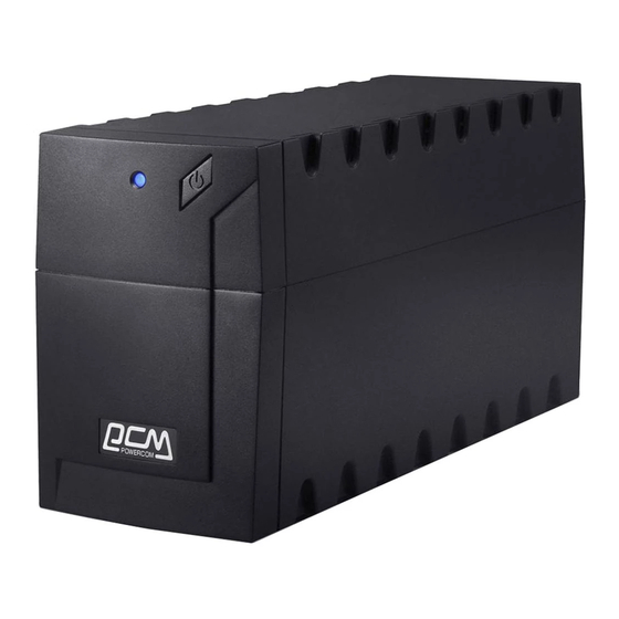
- Page 1 U P S Uninterruptible Power System Line Interactive Network Protection Pure Sine Wave Output UPS Regular models600A/800A/1000A/1250A 1500A/2000A/2500A/3000A & Extended Run-Time Models 1000AL/2000AL/3000AL USER’S MANUAL Printed in USA...
- Page 2 Important safety instructions Thank you for selecting this uninterruptible power system (UPS). It provides you with better protection for connected equipment. Please read this manual! This manual provides safety, installation and operating instructions that will help you derive the fullest performance and service life that the UPS has to offer. Please save this manual! It includes important instructions for the safe use of this UPS and for obtaining factory service should the proper operation of the UPS come into question.
-
Page 3: Table Of Contents
Table of contents 1 . I n t r o d u c t i o n ………………… …………………………… ……………………. . 4 2 . S a f e t y ……………………………………………………………………………. . 5 3 . P r e s e n t a t i o n ……………………………………………………………………. 6 Front Panel Rear Panel Output... -
Page 4: Introduction
1. INTRODUCTION The product is line interactive UPS with the newest technology and powerful function. The LINE INTERACTIVE UPS is with AVR function allows input voltage range from 75% to 125%, including on line voltage boost-up & buck down. An ideal protection equipment for critical connected loads. -
Page 5: Presentation
CAUTION ! ∨ To reduce the risk of electric shock, disconnect the UPS from the mains supply before installing a computer interface signal cable. Reconnect the power cord only after signaling interconnections have been made. ∨ The internal energy source(the battery) cannot be de-energized by the user. The output may be energized when the unit is not connected to a mains supply. -
Page 6: Rear Panel
power the loads. ON/TEST also activates the UPS's self-test and utility line voltage displays. 3.2 " OVERLOAD" indicator (RED LED) The LED lights when the loads connected to the UPS exceed the UPS's capacity. See Section 6.3. 3.3 "BACK UP" indicator (GREEN LED) The LED illuminates when the UPS is supplying battery power to the loads. -
Page 7: I N S T A L L A T I O
battery ! 3.13 SNMP INTERFACE PORT (optional) Provide the SNMP adapters for 10-BaseT Ethernet and Token Ring connectors. Through RS232 communication port, the SNMP adapter make your UPS becomes "SNMP manageable", provide a real time UPS and power status information for the network manager. Note: It's not necessary to use this function. - Page 8 RUPS series software (or other power management software) and an interface kits can be used with this UPS. Use only kits supplied or approved by the manufacturer. If used, connect the interface cable to the 9 pin computer interface port on the back panel of the UPS. Note: Computer interface connection is optional.
-
Page 9: O P E R A T I O
computer equipment. A laser printer or plotter periodically draws significantly more power than when idle, and may overload the UPS. 4.8 Check the Site Wiring Fault Indicator After plugging in the loads and the UPS, check the site wiring fault indicator on the rear panel. - Page 10 5.3 Self-test Use the self-test to verify both the operation of the UPS and the condition of the battery. In normal utility power, push the ON/TEST button more than 1 second and UPS performs a self-test function. During the self-test, the UPS operates a back up mode.
-
Page 11: Alarm
6. Alarm 6.1 "BACK UP" (slow alarm) When in BACK UP mode, the YELLOW LED illuminates and the UPS sounds an audible alarm. The alarm stops when the UPS returns to LINE NORMAL operation. Press the ON/TEST button during on-battery alarms to stop the beeping. 6.2 "LOW BATTERY"... -
Page 12: M A I N T E N A N C
Caution: Use only factory supplied or authorized UPS monitoring cable ! 8. Maintenance 1. Keep the unit clean and vacuum the ventilation intake periodically. 2. Wipe with soft loose and damp cloth. 3. Check for loose and bad connections monthly. 4. - Page 13 2. Pin 5 generates a High to Low signal when the battery inside the UPS has less than 5 minutes back up time left. 3. Pin 2 generates a High to Low signal when the line is fail. 4. The UPS will shut down when a high RS-232 level is sustained on pin 6 for 0.36 seconds.
- Page 14 8) Place your new battery in the same position/direction and reconnect the wires red wire-position(+) and black wire negative(-) 9) Please follow steps 5,4 and 3 (in that order) to reconnect the entire unit. 10) Please follow manual instructions in order to properly reconnect your equipment.
- Page 15 The UPS is overloaded Check the UPS’ s load display Remove nonessential equipments Front panel indicators The UPS has been shut None. The UPS will restart automatically flash down by remote control when utility power returns. sequentially All indicators are flash Internal UPS fault Do not attempt to use the UPS.
- Page 16 3. Insert the battery pack connector into the UPS. To install additional battery packs, repeat this procedure using the battery pack connectors on the battery packs. Note: Do not stack battery packs. 14. Specifications MODEL 600A 800A 1000A 1250A 1500A 2000A...
- Page 17 Protection Automatic self-test & discharge protection, Replace battery indicator Back - up Time 10 - 30 minutes (depending on computer load) PHYSICAL Net Weight 13.8 14.5 15.8 Kg(lbs) (30.4) (31.9) (33.0) (34.8) (55.0) (66.0) Shipping Weight 14.8 15.5 16.8 Kg(lbs) (32.6) (34.1) (35.2)
- Page 18 Automatic self-test & discharge protection, Replace battery indicator Protection Back - up Time 10 - 30 minutes (depending on computer load) PHYSICAL Net Weight 18.0 23.5 26.1 28.4 55.2 57.8 Kg(lbs) (39.6) (51.7) (57.4) (62.4) (121.4) (127.1) Shipping Weight 19.5 25.0 27.7 30.0...
- Page 19 Nominal Battery Voltage Built-in Charge Current Supplied Battery Built-in External pack Depend on request Packs Protection Automatic self-test & discharge protection, Replace battery indicator Back - up Time 10 - 30 minutes (depending on computer load) Net Weight (Kg) (220V)30 PHYSICAL (110V) (220V)
Need help?
Do you have a question about the 600A and is the answer not in the manual?
Questions and answers