
Related Manuals for Perkins 1206F-E70TA


Summary of Contents for Perkins 1206F-E70TA
- Page 1 SEBU8732 September 2013 Operation and Maintenance Manual 1206F-E70TA and 1206F-E70TTA Industrial Engines BM (Engine) BN (Engine)
-
Page 2: Important Safety Information
These changes can affect the service that is given to the product. Obtain the complete and most current information before you start any job. Perkins dealers or Perkins distributors have the most current information available. When replacement parts are required for this product Perkins recommends using Perkins replacement parts. -
Page 3: Table Of Contents
SEBU8732 Table of Contents Table of Contents Maintenance Section Refill Capacities..........74 Foreword............4 Maintenance Recommendations....88 Safety Section Maintenance Interval Schedule ...... 91 Safety Messages..........5 Warranty Section General Hazard Information ......8 Warranty Information .... -
Page 4: Foreword
Operation and Maintenance Manual except for the Operation interval and the maintenance items in that interval. Major repairs should only be carried out by Perkins Operating techniques outlined in this manual are authorized personnel. Your Perkins dealer or your basic. They assist with developing the skills and... -
Page 5: Safety Section
If a warning sign is attached to a part of the engine that is replaced, install a new warning sign on the replacement part. Your Perkins dealer or your Perkins distributor can provide new warning signs. Universal Warning 1... -
Page 6: Ether Warning
SEBU8732 Safety Section Safety Messages Illustration 1 g03022899 Typical example The universal warning label is install in two positions on the engine. On the valve mechanism cover and on the intake manifold, refer to illustration 1 . Ether Warning 2 Do not use aerosol types of starting aids such as ether. - Page 7 SEBU8732 Safety Section Safety Messages The ether warning label is installed on the intake manifold, refer to illustration 2 . Hand (High Pressure) 3 Contact with high pressure fuel may cause fluid penetration and burn hazards. High pressure fuel spray may cause a fire hazard. Failure to follow these inspection, maintenance and service in- structions may cause personal injury or death.
-
Page 8: General Hazard Information
SEBU8732 Safety Section General Hazard Information • Tampering with the engine installation or tampering i05192438 with the OEM supplied wiring can be dangerous. General Hazard Information Personal injury, death and/or engine damage could result. • Vent the engine exhaust to the outside when the engine is operated in an enclosed area. - Page 9 SEBU8732 Safety Section General Hazard Information • The engine is stopped. Ensure that the engine • Filler caps cannot be started. • Grease fittings • The protective locks or the controls are in the • Pressure taps applied position. • Breathers •...
-
Page 10: Pressurized Air And Water
SEBU8732 Safety Section General Hazard Information • The engine is stopped. Ensure that the engine cannot be started. • Disconnect the batteries when maintenance is performed or when the electrical system is serviced. Disconnect the battery ground leads. Tape the leads in order to help prevent sparks. •... -
Page 11: Burn Prevention
Asbestos Information Perkins equipment and replacement parts that are shipped from Perkins engine company limited are asbestos free. Perkins recommends the use of only genuine Perkins replacement parts. Use the following guidelines when you handle any replacement parts that contain asbestos or when you handle asbestos debris. -
Page 12: Fire Prevention And Explosion Prevention
Do not allow alkali to contact If the application involves the presence of the skin, the eyes, or the mouth. combustible gases, consult your Perkins dealer and/ or your Perkins distributor for additional information Oils about suitable protection devices. - Page 13 SEBU8732 Safety Section Fire Prevention and Explosion Prevention Do not weld on lines or tanks that contain flammable fluids. Do not flame cut lines or tanks that contain flammable fluid. Clean any such lines or tanks thoroughly with a nonflammable solvent prior to welding or flame cutting.
-
Page 14: Crushing Prevention And Cutting Prevention
Leaks can cause fires. Consult your Perkins dealer or your Perkins distributor for replacement parts. Refer to the OEM for the location of foot and hand holds for your specific application. -
Page 15: High Pressure Fuel Lines
SEBU8732 Safety Section High Pressure Fuel Lines i03550790 High Pressure Fuel Lines Contact with high pressure fuel may cause fluid penetration and burn hazards. High pressure fuel spray may cause a fire hazard. Failure to follow these inspection, maintenance and service in- structions may cause personal injury or death. -
Page 16: Before Starting Engine
SEBU8732 Safety Section Before Starting Engine If you inspect the engine in operation, always use the Do not bypass the automatic shutoff circuits. Do not proper inspection procedure in order to avoid a fluid disable the automatic shutoff circuits. The circuits are provided in order to help prevent personal injury. -
Page 17: Engine Stopping
These engines are equipped with a glow plug starting aid in each individual cylinder that heats the intake air in order to improve starting. Some Perkins engines may have a cold starting system that is controlled by the ECM that allows a controlled flow of ether into the engine. -
Page 18: Engine Electronics
SEBU8732 Safety Section Engine Electronics i05192488 Engine Electronics Tampering with the electronic system installation or the OEM wiring installation can be dangerous and could result in personal injury or death and/or engine damage. Electrical Shock Hazard. The electronic unit injec- tors use DC voltage. - Page 19 However, the monitoring system and the engine monitoring control will be similar for all engines. Note: Many of the engine control systems and display modules that are available for Perkins engines will work in unison with the Engine Monitoring System. Together, the two controls will provide the engine monitoring function for the specific engine application.
-
Page 20: Product Information Section
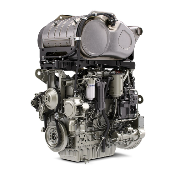
General Information i05192513 Model View Illustrations The following model views show typical features of the engine. Due to individual applications, your engine may appear different from the illustrations. 1206F-E70TA Single Turbocharged Engine with Installed Aftertreatment Illustration 15 g03393436 Typical example... - Page 21 SEBU8732 General Information Model View Illustrations 1206F-E70TTA Engine Views with Series Turbochargers Illustration 16 g03387645 Typical example (1) Rear engine lifting eye (4) Alternator (7) Back pressure valve (2) High-pressure turbocharger (5) Low-pressure turbocharger (3) Front engine lifting eye (6) Oil drain plug...
- Page 22 SEBU8732 General Information Model View Illustrations Illustration 17 g03387666 Typical example (8) Secondary fuel filter (12) Flywheel housing (17) Oil level gauge (Dipstick) (9) Primary fuel filter (13) Flywheel (18) Oil drain tap (10) Crankcase breather (14) Solenoid for starting motor (19) location for the oil sampling valve (11) Engine Electronic Control Module (15) Starting motor...
- Page 23 SEBU8732 General Information Model View Illustrations Illustration 18 g03387667 Typical example (21) NOx Reduction system (NRS) (24) Oil filler cap (27) Crankshaft damper (22) Air intake (25) Water pump (28) Belt tensioner (23) Coolant outlet (26) Coolant intake (29) Belt...
- Page 24 SEBU8732 General Information Model View Illustrations Off Engine Components Illustration 19 g03387619 Items that can be supplied loose. (1) Clean emission module (5) NOx sensors (9) Flexible exhaust pipe assembly (2) Pump electronics tank unit (6) In-line fuel filter (9 A) Protection sleeve for flexible exhaust (3) Heated line (7) Priming/tranfer fuel pump pipe...
- Page 25 SEBU8732 General Information Model View Illustrations Engine Aftertreatment System Illustration 20 g03027726 Typical example (1) Clean Emission Module (CEM) (3) Exhaust intake connection (5) Diesel Exhaust Fluid (DEF) injector (2) Lifting eyes for CEM (4) Exhaust outlet connection...
-
Page 26: Product Description
Diesel Particulate Filter (DPF), and the Selective Catalytic Reduction (SCR). The SCR requires the use There are two variants of the Perkins industrial engine, the 1206F-E70TA a single turbocharged of Diesel Exhaust Fluid (DEF) to be injected into the engine. -
Page 27: Engine Specifications
SEBU8732 General Information Product Description For more information on DEF, refer this Operation and (Table 2, contd) Maintenance Manual, “Fluid Recommendations”. Stroke 135 mm (5.31495 inch) Engine Specifications 151 to 205 kW Power (202.5 to 274.9 hp) Note: The front end of the engine is opposite the Aspiration Turbocharged charge cooled flywheel end of the engine. -
Page 28: Engine Cooling And Lubrication
Aftertreatment System • Gear-driven centrifugal water pump The aftertreatment system is approved for use by Perkins . In order to be emission-compliant only the • Water temperature regulator which regulates the approved Perkins aftertreatment system must be engine coolant temperature used on a Perkins engine. -
Page 29: Product Identification Information
Plate Locations and Film Locations (Aftertreatment System) Clean Emission Module (CEM) Illustration 23 g03046077 Perkins engines are identified by an engine serial number. An example of an engine number is BN*****U000001J. ***** The list number for the engine Type of engine... -
Page 30: Emissions Certification Film
Typical example PETU serial plate Record the information on the CEM and PETU serial Pump Electronic Tank Unit (PETU) plates. The information will be required by your Perkins dealer or your Perkins distributor in order to identify replacement part numbers. i05193198 Emissions Certification Film The label for the emission is installed on the front gear cover. -
Page 31: Reference Information
SEBU8732 Product Identification Information Reference Information Secondary Fuel Filter Element Lubrication Oil Filter Element Auxiliary Oil Filter Element Total Lubrication System Capacity Total Cooling System Capacity Air Cleaner Element Drive Belt Clean Emission Module Part Number Serial Number Pump Electronics Tank Unit Part Number Serial Number Illustration 29... -
Page 32: Operation Section
SEBU8732 Operation Section Product Lifting Operation Section Engine and Clean Emission Module (CEM) Lifting and Storage i05350494 Product Lifting NOTICE Never bend the eyebolts and the brackets. Only load the eyebolts and the brackets under tension. Remem- ber that the capacity of an eyebolt is less as the angle between the supporting members and the object be- comes less than 90 degrees. - Page 33 SEBU8732 Lifting and Storage Product Lifting Illustration 32 g03419909 Typical example (3) Lifting eyes for PETU Refer to illustration 32 for the location of the lifting eyes in order to lift the PETU. Illustration 31 g03051677 Typical example (2) Lifting eyes for the CEM Refer to illustration 31 for the location of the lifting eyes in order to lift the CEM.
-
Page 34: Condition For Storage
The engine must be stored in a water proof building. The building must be kept at a constant temperature. Engines that are filled with Perkins ELC will have coolant protection to an ambient temperature of −36° C (−32.8° F). The engine must not be subjected to extreme variations in temperature and humidity. -
Page 35: Open Cooling System
SEBU8732 Lifting and Storage Product Storage Open Cooling System On removal from storage the DEF quality in the tank must be tested with a refractometer. The DEF in the tank must meet the requirements defined in ISO Ensure that all cooling drain plugs have been 22241-1 and comply with table 3 . -
Page 36: Features And Controls
SEBU8732 Features and Controls Alarms and Shutoffs Features and Controls Intake manifold pressure – The intake manifold pressure sensor checks the rated pressure in the engine manifold. i05416516 Fuel rail pressure – The fuel rail pressure sensor Alarms and Shutoffs measures the high pressure or low pressure in the fuel rail. -
Page 37: Warning Strategy
SEBU8732 Features and Controls Selective Catalytic Reduction Warning System Warning Strategy before the SCR module monitor the temperatures within the system. The Electronic Control Module (ECM) will have either a world-wide warning strategy or a European union warning strategy enabled within the ECM software. Pump Electronics Tank Unit (PETU) Alarms and Shutoff The European union warning strategy is comprised of... - Page 38 The stop lamp will be on solid Contact your Perkins dealer or your Perkins Distributor at level 1 warning, do not let the fault develop. Table 5 World-Wide NOx Reduction System Fault Normal operation...
- Page 39 The stop lamp will activate Contact your Perkins dealer or your Perkins Distributor at level 1 warning, do not let the fault develop. World-Wide DEF Level Warnings Two options are available but only one option will be enabled.
-
Page 40: Gauges And Indicators
Determine and correct the cause of any significant change in the readings. Consult your Perkins dealer or your Perkins distributor for assistance. Some engine applications are equipped with Indicator Lamps. Indicator lamps can be used as a diagnostic aid. -
Page 41: Indicator Lamps
3. Inspect the cooling system for leaks. If necessary, The lamps will illuminate for 2 seconds in order to consult your Perkins dealer or your Perkins check that the lamps are functioning when the keyswitch is turned to the ON position. If any of the distributor for assistance. -
Page 42: Monitoring System (Engine Indicators And)
SEBU8732 Features and Controls Monitoring System The wait to disconnect lamp will be illuminated during engine operation and will be extinguished approximately 2 minutes after the engine has stopped. Do not disconnect the battery disconnect switch during the period the lamp is illuminated. The diesel exhaust fluid system will be purged during this time. -
Page 43: Aftertreatment System
1. One or more of the shutdown values for diagnostic code. the engine protection strategy has been exceeded. Contact your Perkins dealer or your Perkins distributor. 2. A serious active diagnostic code has been detected. If install, the audible warning will sound. -
Page 44: Engine Components
SEBU8732 Features and Controls Sensors and Electrical Components Engine Components Illustration 37 g03389319 Typical example (1) Coolant Temperature Sensor (6) Inlet Manifold Air Temperature Sensor (13) Primary Speed/Timing Sensor (2) Injector Connector for Number One and (7) Inlet Manifold Air Pressure Sensor (14) Starter Solenoid Two Injectors (8) Glow Plug Connection... - Page 45 SEBU8732 Features and Controls Sensors and Electrical Components Illustration 38 g03389322 Typical example (20) Wastegate Regulator (22) Temperature Sensor for the NRS (25) Back Pressure Valve (21) Control Valve for the NOx Reduction (23) Intake Pressure for the NRS System (NRS) (24) Differential Pressure for the NRS...
- Page 46 SEBU8732 Features and Controls Sensors and Electrical Components Illustration 39 g03389323 Typical example (26) Alternator (27) Secondary Speed/Timing sensor (28) Exhaust Temperature Sensor...
- Page 47 SEBU8732 Features and Controls Sensors and Electrical Components Illustration 40 g03393046 Typical example (29) Water in Fuel Switch (30) Inlet Air Temperature Some applications do not require a diagnostic connector (9) installed in the engine wiring harness. The Inlet air temperature sensor (30) will be installed in the induction system between the air cleaner and the inlet manifold.
- Page 48 SEBU8732 Features and Controls Sensors and Electrical Components Illustration 42 g03393011 Typical example (9) Diagnostic connector (10) Electronic Control Module (11) Atmospheric Pressure Sensor (Barometric Pressure sensor) (12) Oil pressure sensor Illustration 43 g03392999 Typical example (13) Primary Speed/Timing Sensor...
- Page 49 SEBU8732 Features and Controls Sensors and Electrical Components Illustration 44 g03393000 Typical example (14) Starter Solenoid (16) Starter Relay (15) Starting Motor (17) Oil Level Switch Illustration 45 g03393004 Typical example (18) Fuel Temperature Sensor (19) Solenoid for High Pressure Fuel Pump...
- Page 50 SEBU8732 Features and Controls Sensors and Electrical Components Illustration 46 g03393005 Typical example (20) Wastegate Regulator (22) Temperature Sensor for the NRS (24) Differential Pressure for the NRS (21) Control Valve for NRS (23) Intake Pressure for the NRS...
- Page 51 SEBU8732 Features and Controls Sensors and Electrical Components Illustration 47 g03393010 Typical example (25) Back Pressure valve (26) Alternator...
- Page 52 SEBU8732 Features and Controls Sensors and Electrical Components Illustration 48 g03393006 Typical example (27) Secondary Speed/Timing sensor (28) Exhaust Temperature Sensor...
- Page 53 SEBU8732 Features and Controls Sensors and Electrical Components Aftertreatment Components Illustration 49 g03393078 Clean Emissions Module (CEM) Illustration 50 g03393624 (1) Clean Emission Module (2) Gas Intake Temperature Sensor (3) Soot Sensor Antenna (4) Location for NOx Sensing Element (5) Soot Sensor Antenna (6) Diesel Exhaust Fluid Injector (7) Temperature Sensor Connector (8) Identification Module...
- Page 54 SEBU8732 Features and Controls Sensors and Electrical Components CEM Sensors Illustration 51 g03393632 (2) Gas Intake Temperature Sensor (4) Location for NOx Sensing Element (6) Diesel Exhaust Fluid Injector (3) Soot Sensor Antenna (5) Soot Sensor Antenna Illustration 52 g03393634 (7) Temperature Sensor Connector (9) Gas Temperature Sensor before (8) Identification Module...
- Page 55 SEBU8732 Features and Controls Sensors and Electrical Components Soot and NOx Sensors Illustration 53 g03393956 (10) Soot Sensor (11) NOx Sensors The location of the soot sensor (10) and NOx sensor (11) will depend on the application.
- Page 56 SEBU8732 Features and Controls Sensors and Electrical Components Pump Electronic Tank Unit (PETU) Illustration 54 g03393959 (1) DEF Level Sensor and DEF Temperature (3) Customer Connections (6) Voltage Limiting Protection Module Sensor (4) Dosing Control Module (2) Coolant Diverter Valve (5) Relays...
- Page 57 SEBU8732 Features and Controls Sensors and Electrical Components Heated Line Illustration 55 g03393960 Typical example (7) Heated line...
-
Page 58: Engine Diagnostics
3. A flashing YELLOW lamp indicates a 3-digit diagnostic code for the engine. The sequence of flashes represents the system diagnostic Perkins Electronic Engines have the capability to perform a self-diagnostics test. When the system message. Count the first sequence of flashes in detects an active problem, a diagnostic lamp is order to determine the first digit of the flash code. -
Page 59: System Configuration Parameters
SEBU8732 Engine Diagnostics Engine Operation with Intermittent Diagnostic Codes Note: If the customer has selected “DERATE” and if The electronic service tool is required in order to alter the configuration parameters. there is a low oil pressure condition, the Electronic Control Module (ECM) will limit the engine power until System Configuration Parameters the problem is corrected. -
Page 60: Customer Specified Parameters
SEBU8732 Engine Diagnostics Configuration Parameters Table 9 System Configuration Parameters Configuration Parameters Record Engine Serial Number Factory Installed Aftertreatment #1 Identification Number DPF #1 Soot Loading Sensing System Configuration Code Limp Home Engine Speed Ramp Rate System Operating Voltage Configuration Rating Number CAN Communication Protocol Write Security Engine Emissions Operator Inducement Progress Configuration... - Page 61 SEBU8732 Engine Diagnostics Configuration Parameters (Table 10, contd) Engine Idle Shutdown Ambient Temperature Override Enable Status High Soot Load Aftertreatment Protection Enable Status Air Shutoff Throttle Lock Feature Installation Status PTO Mode Throttle Lock Engine Set Speed #1 Throttle Lock Engine Set Speed #2 Throttle Lock Increment Speed Ramp Rate Throttle Lock Decrement Speed Ramp Rate Throttle Lock Engine Set Speed Increment...
- Page 62 SEBU8732 Engine Diagnostics Configuration Parameters (Table 10, contd) Engine Cooling Fan Minimum Air Flow Coolant Temperature Engine Cooling Fan Control Transmission Oil Temperature Input Enable Status Engine Cooling Fan Maximum Air Flow Transmission Oil Temperature Engine Cooling Fan Minimum Air Flow Transmission Oil Temperature Engine Cooling Fan Control Hydraulic Oil Temperature Input Enable Status Engine Cooling Fan Maximum Air Flow Hydraulic Oil Temperature Engine Cooling Fan Minimum Air Flow Hydraulic Oil Temperature...
-
Page 63: Engine Starting
SEBU8732 Engine Starting Before Starting Engine Engine Starting i05360375 Cold Weather Starting i04935860 Before Starting Engine Perform the required daily maintenance and other Do not use aerosol types of starting aids such as periodic maintenance before the engine is started. ether. -
Page 64: Starting The Engine
SEBU8732 Engine Starting Starting the Engine 4. Allow the keyswitch to return to the RUN position 3. When the warning light for the glow plugs is after the engine starts. extinguished cycle the keyswitch. Turn the keyswitch to the OFF position and then to the 5. -
Page 65: After Starting Engine
SEBU8732 Engine Starting After Starting Engine Note: If it is possible, first diagnose the reason for the After jump starting, the alternator may not be able to fully recharge batteries that are severely discharged. starting failure. Refer to Troubleshooting, “Engine Will The batteries must be replaced or charged to the Not Crank and Engine Cranks But Will Not Start”... -
Page 66: Engine Operation
SEBU8732 Engine Operation Engine Operation Engine Operation The DPF may require the exhaust gas temperature to rise in order to remove the soot. If necessary, the back pressure valve operates in order to create the rise in temperature. In some applications, the i04907268 operation of the back pressure valve will make the Engine Operation... -
Page 67: Fuel Conservation Practices
Fuel Conservation Practices The efficiency of the engine can affect the fuel economy. Perkins design and technology in manufacturing provides maximum fuel efficiency in all applications. Follow the recommended procedures in order to attain optimum performance for the life of the engine. -
Page 68: Cold Weather Operation
• The cooling system and the lubrication system for Perkins Diesel Engines can operate effectively in the engine do not lose heat immediately upon cold weather. During cold weather, the starting and shutdown. -
Page 69: Viscosity Of The Engine Lubrication Oil
A block heater can be 110 V dc or • Pushrods may become bent. 240 V dc. The output can be 750/1000W. Consult your Perkins dealer or your Perkins distributor for • Other damage to valve train components can more information. -
Page 70: Radiator Restrictions
Note: Only use grades of fuel that are recommended by Perkins . Refer to this Operation and Maintenance Consult with your Perkins dealer or your Perkins Manual, “Fluid Recommendations”. -
Page 71: Fuel Filters
SEBU8732 Cold Weather Operation Fuel Related Components in Cold Weather • Glow plugs (if equipped) Drain the water and sediment from any fuel storage tank at the following intervals: weekly, service • Engine coolant heaters, which may be an OEM intervals and refueling of the fuel tank. -
Page 72: Engine Stopping
SEBU8732 Engine Stopping Stopping the Engine Engine Stopping Note: There may be regulations that define the requirements for the operator and/or support personnel to be present when the engine is running. i05406628 Stopping the Engine Leaving the machine unattended when the engine is running may result in personal injury or death. -
Page 73: After Stopping Engine
SEBU8732 Engine Stopping After Stopping Engine i05402556 After Stopping Engine Pressurized System: Hot coolant can cause seri- ous burns. To open the cooling system filler cap, stop the engine and wait until the cooling system components are cool. Loosen the cooling system Note: Before you check the engine oil, do not operate pressure cap slowly in order to relieve the the engine. -
Page 74: Maintenance Section
SEBU8732 Maintenance Section Refill Capacities Maintenance Section i04229329 Fluid Recommendations Refill Capacities General Coolant Information i04907690 Refill Capacities NOTICE Never add coolant to an overheated engine. Engine damage could result. Allow the engine to cool first. Lubrication System NOTICE The refill capacities for the engine crankcase reflect If the engine is to be stored in, or shipped to an area the approximate capacity of the crankcase or sump with below freezing temperatures, the cooling system... -
Page 75: Coolant Recommendations
Supplement Coolant Additive • Reduction of heat transfer • ASTM American Society for Testing and Materials • Leakage of the water pump seal The following two coolants are used in Perkins • Plugging of radiators, coolers, and small passages diesel engines:... -
Page 76: Elc Cooling System Maintenance
Acceptable – A commercial heavy-duty antifreeze contains organic corrosion inhibitors and antifoam that meets ASTM D6210 specifications agents with low amounts of nitrite. Perkins ELC has been formulated with the correct amount of these additives in order to provide superior corrosion NOTICE protection for all metals in engine cooling systems. - Page 77 9. Fill the cooling system with the Perkins Premixed the coolant level stabilizes. As needed, add the coolant mixture in order to fill the system to the ELC.
-
Page 78: General Lubricant Information
X is the amount of SCA that is required. hydrometer should not be used. Perkins engine cooling systems should be tested at Table 20 is an example for using the equation that is 500 hour intervals for the concentration of SCA. -
Page 79: Engine Oil
“Fluid Recommendations/ Note: These engine oils are not approved by Engine Oil” topic (Maintenance Section). Perkins and these engine oils must not be used: CC, CD, CD-2, CF-4, CG-4, CH-4 and CI-4. Engine Oil Lubricant Viscosity Recommendations... - Page 80 An infrared analysis is used to compare the properties of new oil to the Perkins does not recommend the use of aftermarket additives in oil. It is not necessary to use aftermarket properties of the used oil sample. This analysis...
-
Page 81: General Fuel Information
SEBU8732 Refill Capacities Fluid Recommendations Specification Storage DEF that is used in Perkins engines must meet the Table 22 ISO specification 22241-1 for quality. The ISO Storage Temperature Expected DEF Life specification 22241-1 requirements are met by many brands of DEF, including those that carry the AdBlue Below 25°... -
Page 82: Diesel Fuel Requirements
Contact your local Perkins distributor for the most up-to-date recommendations. Diesel Fuel Requirements Perkins is not in a position to continuously evaluate and monitor all worldwide distillate diesel fuel specifications that are published by governments and technological societies. - Page 83 Engines that are manufactured by Perkins are NOTICE certified with the fuel that is prescribed by the United The Perkins 1200 series of diesel engine must be op- States Environmental Protection Agency . Engines erated using Ultra Low Sulfur Diesel. The sulphur that are manufactured by Perkins are certified with content of this fuel must be lower than 15 PPM.
-
Page 84: Diesel Fuel Characteristics
“EU Off Road Diesel fuel. Acceptable from 2011 MUST have less than 10 PPM sulfur level” All the fuels must comply with the specification in the table for the Perkins Specification Distillate Diesel Fuel . Diesel Fuel Characteristics The viscosity of the fuel is significant because fuel serves as a lubricant for the fuel system components. - Page 85 Protection Agency (EPA) and European Certification eter as tested by ISO 12156-1. Fuel with higher wear fuels. Perkins does not certify engines on any other scar diameter than 0.52 mm (0.0205 inch) will lead to fuel. The user of the engine has the responsibility of...
- Page 86 Consult your supplier of fuel for • Perkins recommend the use of oil analysis in assistance in selecting appropriate anti-microbial order to check the quality of the engine oil if additive.
- Page 87 80 hours. dependant requirements and a range of options. The Perkins fuel cleaner can be used on an on-going options can be applied differently in each country. basis with no adverse impact on engine or fuel There are five classes that are given to arctic climates system durability.
-
Page 88: Maintenance Recommendations
Consult the OEM of the equip- To relieve the pressure from the coolant system, turn ment or your Perkins dealer regarding welding on a off the engine. Allow the cooling system pressure cap chassis frame or rail. - Page 89 SEBU8732 Maintenance Recommendations Welding on Engines with Electronic Controls 3. Disconnect the negative battery cable from the battery. If a battery disconnect switch is provided, open the switch. 4. Disconnect all electronic components from the wiring harnesses. Include the following components: •...
-
Page 90: Severe Service Application
• Failure to use recommended fuel, lubricants, and coolant/antifreeze Refer to the standards for the engine or consult your Perkins dealer or your Perkins distributor in order to determine if the engine is operating within the defined parameters. Severe service operation can accelerate component wear. -
Page 91: Maintenance Interval Schedule
SEBU8732 Maintenance Recommendations Maintenance Interval Schedule “Engine Oil and Filter - Change”......111 i05196439 Maintenance Interval Schedule “Fuel Filter (In-Line) - Replace”......114 “Fuel System Primary Filter (Water Separator) Element - Replace”..........115 When Required “Fuel System Secondary Filter - Replace” ....118 “Battery - Replace”...........92 “Radiator - Clean”... -
Page 92: Battery - Replace
Aftercooler Core - Clean/Test Alternator - Inspect (Air-To-Air Aftercooler) Perkins recommends a scheduled inspection of the alternator. Inspect the alternator for loose The air-to-air aftercooler is OEM installed in many connections and correct battery charging. Check the applications. Please refer to the OEM specifications ammeter (if equipped) during engine operation in for information that is related to the aftercooler. -
Page 93: Battery Electrolyte Level - Check
SEBU8732 Maintenance Recommendations Battery Electrolyte Level - Check i02747977 Battery Electrolyte Level - The battery cables or the batteries should not be Check removed with the battery cover in place. The bat- tery cover should be removed before any servic- ing is attempted. -
Page 94: Battery Or Battery Cable - Disconnect
SEBU8732 Maintenance Recommendations Battery or Battery Cable - Disconnect i05424317 i04907925 Battery or Battery Cable - Belt Tensioner - Check Disconnect The battery cables or the batteries should not be removed with the battery cover in place. The bat- tery cover should be removed before any servic- ing is attempted. -
Page 95: Belt - Inspect
SEBU8732 Maintenance Recommendations Belt - Inspect • The engine overheats frequently. i04907868 Belt - Inspect • Foaming is observed. • The oil has entered the cooling system and the coolant is contaminated. • The fuel has entered the cooling system and the coolant is contaminated. - Page 96 Flush 1. Flush the cooling system with clean water and a suitable cleaning agent in order to remove any debris. Refer to your Perkins dealer or distributor for suitable cleaning agents. 2. Install connection hose. Clean the drain plugs. Install the drain plugs. Tighten drain plug securely.
-
Page 97: Coolant (Elc) - Change
Clean the drain plugs and install new O NOTICE ring seal. Install the drain plugs and tighten to a Perkins ELC must be using with an extender in order to achieve 12000 hours operation. For more informa- torque of 35 N·m (25 lb ft). - Page 98 Allow the coolant to drain. For information regarding the disposal and the recycling of used coolant, consult your Perkins dealer or Perkins distributor. Flush 1. Flush the cooling system with clean water in order...
-
Page 99: Coolant Level - Check
Loosen the cooling system filler cap slowly in order to relieve any pressure. Remove the cooling In order for Perkins ELC to achieve 12000 hours an system filler cap. Remove the connection hose extender must be added at 6000 hours. For a suitable and remove the cooling system drain plugs. -
Page 100: Diesel Exhaust Fluid - Fill
SEBU8732 Maintenance Recommendations Crankshaft Vibration Damper - Inspect 2. Maintain the coolant level at the maximum mark that is correct for your application. If the engine is equipped with a sight glass, maintain the coolant level to the correct level in the sight glass. Illustration 68 g01950241 Typical example... -
Page 101: Driven Equipment - Check
SEBU8732 Maintenance Recommendations Diesel Exhaust Fluid Filter - Clean/Replace Illustration 70 g03417998 Illustration 71 g03097598 Typical example 1. Ensure that the area around the Diesel Exhaust Fluid (DEF) filter is clean and free from dirt. Use a 1. Ensure that the DEF cap (1) and the surrounding 27mm Bi-Hex socket in order to remove filter cap area is clean and free from dirt. -
Page 102: Engine - Clean
Steam cleaning the engine will remove accumulated Note: The air filter system may not have been oil and grease. A clean engine provides the following provided by Perkins . The procedure that follows is benefits: for a typical air filter system. Refer to the OEM information for the correct procedure. -
Page 103: Cleaning The Primary Air Cleaner Elements
SEBU8732 Maintenance Recommendations Engine Air Cleaner Element (Dual Element) - Inspect/Clean/Replace Cleaning the Primary Air Cleaner The primary air cleaner element can be used up to six times if the element is properly cleaned and properly Elements inspected. The primary air cleaner element should be replaced at least one time per year. -
Page 104: Engine Air Cleaner Element (Single Element) - Inspect/Replace
SEBU8732 Maintenance Recommendations Engine Air Cleaner Element (Single Element) - Inspect/Replace Inspecting the Primary Air Cleaner Pressurized air can be used to clean primary air cleaner elements that have not been cleaned more Elements than three times. Use filtered, dry air with a maximum pressure of 207 kPa (30 psi). -
Page 105: Test The Service Indicator
SEBU8732 Maintenance Recommendations Engine Air Cleaner Service Indicator - Inspect Some engines are equipped with a differential gauge NOTICE for inlet air pressure. The differential gauge for inlet Never service the air cleaner element with the engine air pressure displays the difference in the pressure running since this will allow dirt to enter the engine. -
Page 106: Engine Air Precleaner - Check/Clean
Operation and Maintenance Manual, “Engine Description”. Within that section, refer to the title Note: When the engine is operated in dusty “Aftermarket Products and Perkins Engines”. applications, more frequent cleaning is required. The breather element can be serviced from the top... -
Page 107: Top Service
SEBU8732 Maintenance Recommendations Engine Crankcase Breather Element - Replace Top Service Illustration 79 g03090963 3. Remove the old seal (4) and install a new seal. Note: The cut away from section (5) in the top cap allows access to the seal. Illustration 78 g03090965 1. -
Page 108: Bottom Service
SEBU8732 Maintenance Recommendations Engine Crankcase Breather Element - Replace 4. Install a new filter element into the breather body (3). Ensure the correct position of the element, refer to illustration 80 . Align position (A) on the top cap to position (B) on the filter element. Illustration 82 g02346498 Typical example... -
Page 109: Check The System
Note: The engine mounts may not have been supplied by Perkins . Refer to the OEM information 4. Install a new seal (5). Install a new filter element for further information on the engine mounts and the into the bottom cap (2). -
Page 110: Engine Oil Sample - Obtain
Perkins recommends using a sampling valve in order to obtain oil samples. The quality and the consistency of the samples are better when a sampling valve is used. -
Page 111: Engine Oil And Filter - Change
Use of an oil filter that is not recommended by Perkins could result in severe damage to the en- Failure to follow this recommended procedure will gine bearings, crankshaft, etc., as a result of the larg-... -
Page 112: Fill The Oil Pan
SEBU8732 Maintenance Recommendations Engine Oil and Filter - Change Fill the Oil Pan 2. Cut the oil filter open with a suitable tool. Break apart the pleats and inspect the oil filter for metal 1. Remove the oil filler cap. Refer to this Operation debris. -
Page 113: Every 500 Service Hours "Fan Clearance - Check
SEBU8732 Maintenance Recommendations Fan Clearance - Check i05404932 Fan Clearance - Check There are different types of cooling systems that can be installed. Refer to the Original Equipment Manufactory (OEM) for your application for more information. Ensure that the engine is stopped and allow 2 minutes before the battery disconnect switch is turned off. -
Page 114: Fuel System - Prime
SEBU8732 Maintenance Recommendations Fuel Filter (In-Line) - Replace • Gap (A) vertical top position 12 ± 1 mm (0.47244 ± 0.03937 inch). • Gap (A) vertical bottom position 8 ± 1 mm (0.31496 ± 0.03937 inch). After the gap (A) has been checked in the vertical top position or the vertical bottom position, the horizontal position must be checked. -
Page 115: Fuel System Primary Filter (Water Separator)
SEBU8732 Maintenance Recommendations Fuel System Primary Filter (Water Separator) Element - Replace If the engine will not start, refer to Troubleshooting, NOTICE “Engine Cranks but will not Start”. Do not crank the engine continuously for more than 30 seconds. Allow the starting motor to cool for two minutes before cranking the engine again. - Page 116 SEBU8732 Maintenance Recommendations Fuel System Primary Filter (Water Separator) Element - Replace Illustration 91 g03086757 Typical example 3. Install a suitable tube onto drain (3). Open the drain valve (2). Rotate the drain valve counterclockwise. Two full turns are required. Illustration 92 g02148402 4.
-
Page 117: Fuel System Primary Filter/Water Separator - Drain
SEBU8732 Maintenance Recommendations Fuel System Primary Filter/Water Separator - Drain i04925799 Fuel System Primary Filter/ Water Separator - Drain Fuel leaked or spilled onto hot surfaces or electri- cal components can cause a fire. To help prevent possible injury, turn the start switch off when changing fuel filters or water separator elements. -
Page 118: Fuel System Secondary Filter - Replace
SEBU8732 Maintenance Recommendations Fuel System Secondary Filter - Replace 3. Install a suitable tube onto drain (3). Open the drain valve (2). Rotate the drain valve counterclockwise. Two full turns are required. Loosen vent screw (1). 4. Allow the fluid to drain into the container. 5. -
Page 119: Fuel Tank Water And Sediment - Drain
SEBU8732 Maintenance Recommendations Fuel Tank Water and Sediment - Drain 3. Do not use a tool in order to install the filter assembly. Tighten the assembly by hand. Install the filter bowl (2). Turn the filter bowl clockwise until the filter bowl locks into position against the stops. -
Page 120: Hoses And Clamps - Inspect/Replace
SEBU8732 Maintenance Recommendations Hoses and Clamps - Inspect/Replace Open the drain valve on the bottom of the fuel tank in Inspect all hoses for leaks that are caused by the order to drain the water and the sediment. Close the following conditions: drain valve. -
Page 121: Injector (Diesel Exhaust Fluid) - Replace
SEBU8732 Maintenance Recommendations Injector (Diesel Exhaust Fluid) - Replace Pressurized System: Hot coolant can cause seri- ous burns. To open the cooling system filler cap, stop the engine and wait until the cooling system components are cool. Loosen the cooling system pressure cap slowly in order to relieve the pressure. -
Page 122: Radiator - Clean
Maintenance Recommendations Radiator - Clean i02335774 Radiator - Clean The radiator is not usually supplied by Perkins . The following text describes a typical cleaning procedure for the radiator. Refer to the OEM information for further information on cleaning the radiator. -
Page 123: Starting Motor - Inspect
Refer to the Systems Operation, Testing and Adjusting Manual, “Electric Starting System - Test” for more information on the checking procedure and for specifications or consult your Perkins dealer or your Perkins distributor for assistance. i04922217 Turbocharger - Inspect... -
Page 124: Walk-Around Inspection
SEBU8732 Maintenance Recommendations Walk-Around Inspection Engine Installed with High Pressure 5. Check for the presence of oil. If oil is leaking from the back side of the compressor wheel, there is a Turbocharger and Low Pressure possibility of a failed turbocharger oil seal. Turbocharger The presence of oil may be the result of extended engine operation at low idle. - Page 125 Replace any Remove and Install”. For more information, consult damaged high-pressure fuel lines or high-pressure your Perkins dealer or your Perkins distributor. fuel lines that have leaked. Ensure that all clips on the high-pressure fuel lines...
-
Page 126: Engine Aftertreatment
SEBU8732 Maintenance Recommendations Water Pump - Inspect • Inspect the rest of the fuel system for leaks. Look for loose fuel line clamps. • Drain the water and the sediment from the fuel tank on a daily basis in order to ensure that only clean fuel enters the fuel system. -
Page 127: Warranty Section
Contact your Perkins dealer or your Perkins distributor for more information. For customers that have a valid user name and password, for Perkins. com . secure login then go to TIPSS, and the warranty information can be accessed. -
Page 128: Reference Information Section
Maintenance records are a key element of a maintenance program that is correctly managed. Accurate maintenance records can help your Perkins dealer to fine-tune the recommended maintenance intervals in order to meet the specific operating situation. This should result in a lower engine operating cost. -
Page 129: Maintenance Log
SEBU8732 Reference Materials Maintenance Log i05204675 Maintenance Log Table 25 Engine Model Customer Identifier Arrangement Number Serial Number Service Quantity Of Service Item Date Authorization Hours Fuel... - Page 130 Why buy an Extended Service Contract? 1. No surprises - total protection from unexpected repair cost (parts, labor, and travel). 2. Enjoy longer lasting product support from Perkins global network. 3. Genuine Perkins parts ensure continued engine performance. 4. Highly trained technicians carry out all repairs.
-
Page 131: Index
SEBU8732 Index Section Index Flush ............98 Coolant Extender (ELC) - Add ......99 After Starting Engine........65 Coolant Level - Check ........99 After Stopping Engine........73 Crankshaft Vibration Damper - Inspect..100 Aftercooler Core - Clean/Test (Air-To-Air Viscous Damper......... 100 Aftercooler) ............ - Page 132 SEBU8732 Index Section Replace the Oil Filter........111 Fuel System Primary Filter (Water Separator) Engine Oil Level - Check ........110 Element - Replace ........115 Engine Oil Sample - Obtain ......110 Install the New Filter Element .....116 Obtain the Sample and the Analysis...110 Remove the Element ........115 Engine Operation..........
- Page 133 Reference Information........31 Maintenance Section........74 Record for Reference........31 Model View Illustrations........20 Reference Information Section ...... 128 1206F-E70TA Single Turbocharged Engine Reference Material (Extended Service with Installed Aftertreatment....... 20 Contract) ............130 1206F-E70TTA Engine Views with Series Reference Materials ........128 Turbochargers..........
- Page 134 SEBU8732 Index Section Delayed Engine Shutdown (if Equipped) ..72 System Pressure Release....... 88 Coolant System..........88 Engine Oil ............ 88 Fuel System ..........88 Table of Contents..........3 Turbocharger - Inspect ........123 Engine Installed with High Pressure Turbocharger and Low Pressure Turbocharger..........
- Page 135 Product and Dealer Information Note: For product identification plate locations, see the section “Product Identification Information” in the Operation and Maintenance Manual. Delivery Date: Product Information Model: Product Identification Number: Engine Serial Number: Transmission Serial Number: Generator Serial Number: Attachment Serial Numbers: Attachment Information: Customer Equipment Number: Dealer Equipment...
- Page 136 ©2013 Perkins Engines Compony Limited All Rights Reserved...
Need help?
Do you have a question about the 1206F-E70TA and is the answer not in the manual?
Questions and answers