Table of Contents
Advertisement
Advertisement
Table of Contents
Troubleshooting

Related Manuals for Perkins 103-06


Summary of Contents for Perkins 103-06
- Page 1 Perkins 100 Series: 103-06/103-09/103-10 Perama: M25/M30...
-
Page 3: Table Of Contents
CONTENTS PAGE ABBREVIATIONS and CODES ........................4 FOREWORD ..............................5 SAFETY PRECAUTIONS ..........................6 ENGINE PHOTOGRAPHS ......................... 7 SECTION I Description ............................1-1 SECTION 11 General Engine Data ..........................2-1 SECTION III Dismantling Sequence ........................3-1 SECTION IV Disassembly, inspection, fits and clearances of component assemblies .......... -
Page 4: Abbreviations And Codes
Abbreviations and codes Engine Build List (Parts List) Numbering System The standard engine parts list numbering code system is defined as follows: Code Example: 30226 000001 Code I Engine Type KB = 103.06 KC = 103.09/PERAMA M25 KD = 103.10/PERAMA M30 Code II Engine Parts List Parts list increases numerically for both OEMS and distributors. -
Page 5: Foreword
This publication is produced by the Compact Engines Division Perkins Engines Ltd. and every endeavour is made to ensure that the information contained in this manual is correct at the date publication, but due to continuous... -
Page 6: Safety Precautions
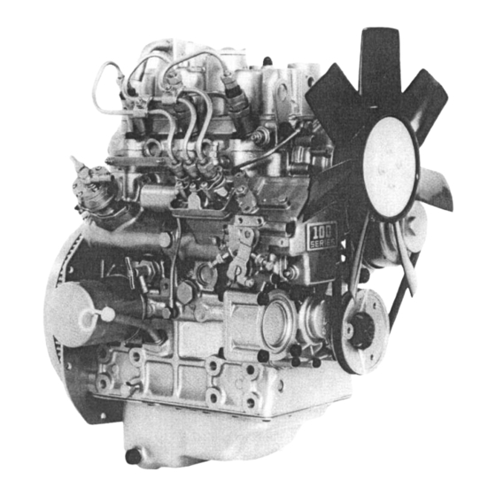
Do not move equipment unless the brakes are in good condition. Ensure that the transmission drive control is in "Neutral" position before the engine is started. Fit only genuine Perkins Parts. Do not use ether to start these engines. - Page 7 ENGINE DIAGRAMS...
- Page 8 Engine cross sectional views...
-
Page 9: Section I
(wrist pin) is made of chrome molybdenum steel alloy hardened by carburizing and The Perkins 100 Series is a three cylinder four stroke, retained by the conventional circlip method. The liquid cooled, compression ignition engine, designed connecting rods are machined from high strength forged for durability, low weight and compactness. - Page 10 Gear Train: Lubricating System: The gear train consists of three helical gears; the A trochoid lobe type oil pump located in the centre of crankshaft gear, located by a woodruff key. The idler the idler gear sends lubricating oil to the main oil galley gear houses the lube oil pump and the cam gear via a relief valve through a spin-on bypass oil filter to the incorporates the governor weight cage.
-
Page 11: General Engine Data
539.6mm Length F/F ..............442mm 489.6mm Width ................390mm 410mm Min. Idle Speeds 103-06/103.09/10 ........800 revs/min Perama M25/M30 ........1000 revs/min Hurth HBW 50 Reverse Gearbox Oil Capacity ....0.30 litres HBW 100 Gearbox Oil Capacity ........ 0.35 litres... - Page 12 Recommended Engine Fluids Coolant ................Clean soft water. Maximum antifreeze concentration 50% (ethanediol base - ethylene glycol with corrosion inhibitor to BS 6850:1985 orASTM D3306-74 or AS 2108-1977) Cetane number-45 minimum Viscosity Fuel - 2.5/4.5 centistokes at 40 C Density-0........
-
Page 13: Dismantling Sequence
SECTION III Dismantling Sequence Rocker Cover Alternator A. Remove breather hose. Loosen and remove A. Remove alternator and adjusting bracket. three cap nuts with washers. Lift rocker cover assembly. Rocker cover PB004 Remove Cooling Fan and Pulley Fuel Injection Pipe A. - Page 14 External Oil Pipe Fuel Lift Pump A. Loosen and remove two banjo bolts at cylinder A. Loosen two cap screws and lift from its bore; block main oil galley and cylinder head remove joint. assembly. B. Remove clamp from fuel injection pump. PB011 PB008 Cylinder Head Assembly...
- Page 15 Crank Pulley Plate Camshaft A. Loosen pulley nut and remove pulley. PBO16 Front End Plate Assembly A. Remove retaining bolts and lift front plate off its locating dowels. Remove joint and discard. Oil Filter A. Remove spin-on type oil filter and discard. Gear Cover and Governor Assembly A.
- Page 16 Connecting Rod and Piston Remove Oil Seal A. Loosen connecting rod nuts and remove rod cap. B. Remove carbon from cylinder bore. Push piston and connecting rod through cylinder block. Replace rod cap to piston assembly. PB022 Crankshaft and Main Bearing Assembly PB020 Flywheel Assembly A.
-
Page 17: Disassembly, Inspection, Fits And Clearances Of Component Assemblies
SECTION IV Disassembly, inspection, fits and clearances of component assemblies Rocker Arm Assembly Standard Clearance Allowable limit - Disassembly 0.032-0.068mm 0.2mm A. Remove the bolt at the rocker arm shaft end. (.001-.026") (.008") B. Pull out the pin located in No. 1 cylinder rocker arm bracket. - Page 18 Cylinder head With a straight edge and a thickness gauge, 6.955-6.97mm 6 89mm check for warping of the cylinder head lower (.274") (271 ) face. Intake valve 103-06 Standard diameter Allowable limit 5.960-5.975mm 5.9mm ( (.2346-.2352") .2323) Exhaust valve 103-09/10/Perama M25/M30...
- Page 19 (098 ) to damage the head. Clean up the insert bore and fit new insert using a press (1,000 to 1,500kgf) and a suit- 103-06 able smooth surface tool. To assist process, Allowable limit Standard width chill the valve seat insert with liquid nitrogen etc or heat the head to between 60 and 1.59-1.80mm (.
- Page 20 P B 1 2 8 E. Inner face of combustion chamber Pull out the cap and insert from the cylinder head. Check and clean the combustion chamber. Cap (not fitted on 103-06) Insert PB036 D. Valve spring Visually inspect the valve spring for damage.
- Page 21 15 kg/cm (5 kg/cm - finish) Finish stroke: 9 Honing depth: 0.04mm (diameter) Cross hatch angle: 40° Surface roughness: 2-4 micron First re-bore 0.5mm (.0196") Bore spec 103-06 Allowable limit Standard bore 64-64.019m m (2. 64 2mm ( 5197-2.5204") 25276...
-
Page 22: Piston
New standard bore Allowable limit New standard bore Allowable limit 72.49-72.505mm 72.7mm 76-76.019mm 76.2mm (2.8539-2.8545") (2.8621") (2.9921-2.9928") (2.9999") Replace Second re-bore block 0.5mm (.0196") Piston and piston rings - Disassembly New standard bore Allowable limit A. Remove piston rings using a piston ring tool. 72.99-73.005mm 73.2mm B. - Page 23 71.9225-71.9375mm 1.0mm 115317389 75.9425-75.9575mm (2.8316-2.8322") oversize (2.9898-2.9904") 115317564 72.4225-72.4375mm 0.5mm oversize (2.8513-2.8519") 115317567 72.9225-72.9375mm 1.0mm 103-06 Piston oversize (2.8710-2.8716") Standard clearance Allowable limit 0.038-0.072mm 0 25mm ( (.0015-.0028") .010) Allowable limit Standard diameter (Piston) 63.948-63.963mm 63 7mm ( (2.5176-2.5182") 2 5079")
-
Page 24: Piston Ring
B. Piston ring d. Oversize piston ring 103-06 a. If the piston ring is worn or damaged, replace If the cylinder is oversized, oversize piston ring set should be employed. b. Piston ring gap Insert the rings into the cylinder at right angle to... -
Page 25: Oil Running Clearance
Allowable limit Standard OD 20.98mm 20.998-21.002mm 103-09/10/Perama M25/M30 (.8259') (.8266-.8268") Standard clearance Allowable limit 0.008-0.023mm 0.08mm (.0003-.0009") (.003") 103-06 Gudgeon pin Standard OD Allowable limit 18.998-19.002mm 18.98mm 103-06 Clearance (.7480-.7481") (.7472") Standard Allowable limit clearance 0.013-0.028mm 0.08mm (.0005-.0011") (.0031") - Page 26 F r o n t 198517110 (1,8096-1.8100") 0.25mm 198517105* 45.714-45.725mm PB049 U.S. 198517114 (1.7997-1.8001") (.0098") B. Thrust clearance 103-06 0.50mm 198517108* 45.464-45.475mm Check the thrust clearance for wear, poor contact, U.S. 198517117 (1.7899-1.7903") burning or other defects. (.0196") N.B. No thrust washers are fitted.
- Page 27 Assemble the connecting rod and connecting 103-06 rod cap, and tighten to the specified torque (3.0- Bearing Crankshaftpin Part No. 3.5kgf.m) (21.7-25.31bf.ft) - 103-09/10/Perama size O.D. dimension (mm) M25/M30, (2.1-2.6kgf.m) (15.2-18.81bf.ft) - 103- S.TD. 34.964-34.975mm 198517310 NOTE: Never rotate the connecting rod.
- Page 28 Face the chamfered part of the bearing holder toward front. Install the bearing holder (.0015-.0041") (.0078") which has reference bit at the centre. Then 103-06 install the bearing holder on which the thrust 0.035-0.102mm 0.2mm washer is to be mounted at the flywheel side ( where fitted).
- Page 29 F After grinding the crankshaft journal, check the oil clearance. Crankshaft journal (bush) 103-06 Bush Bush code No. Crankshaft journal size O.D. finished size (o) S.TD. 198517300 42.964-42.975mm (1.6915-1.6919") U.S.O. 25 198517304 42.714-42.725mm Perama M25/M30 103- (.010") (1.6817-1.6821") 09/10 103-06 U.S.O.
- Page 30 38.464- 38.475mm (1.5143- (1.5118") 1.5147") If the diameter is less than this value, the crankshaft must be replaced with new. 103-06 Crankshaft journal shaft diam. (o) Assy'd std. value Repair req. value Cross Section of Pin and Journal 42.964-42.975 42.90 No.
-
Page 31: Flywheel And Ring Gear
103-09/10/Perama M25/M30 the following specifications: (A) Cam height (intake and exhaust cams) Standard value Allowable limit 26.445-26.5mm 26.1 mm (1.041-1.043") (1.0275") 103-06 Standard value Allowable limit 26.565-26.62mm 26 1mm (1. (1.0459-1.0480") 0275') P B 0 5 7 (A)- Radius at pin/journal 3mm ±... -
Page 32: Camshaft
C. Check the side clearance between the rotor and vane is 0.01 to 0.15mm (.0004 to.006") for 103- 09/ 10/Perama M25/M30, and 0.02 to 0.15mm (. 0008 to .0059") for 103-06. Allowable limit 0. 25mm (.0098"). PB060 1094... -
Page 33: Oil Filter
Water Pump Assembly and Thermostat housing - Disassembly A. Remove the set plate and gasket. B. Take out the thermostat and spring from the thermostat housing (on the 103-06) and from the water pump body on the 103-09/10 and Perama M25/M30. PB066 Water Pump A. -
Page 34: Radiator 103-06/103-09/10
If needed, replace the fuel filter. - Disassembly/Reassembly A. Turn the filter ring nut counterclockwise to remove it. (103-06 only) NOTE: An O-ring is inserted between the ring nut and filter body. This ring should be coated Radiator 103-06/103-09/10 with grease to aid assembly. -
Page 35: Governor
C. Remove the diaphragm from the bottom body, Drain all fuel in the feed pump. Check condition of the top body as follows. Draw air and turn the piston to align the bottom body from IN side with vacuum and put air into groove with the pin hole. - Page 36 The max. fuel has been adjusted at the factory B. Maximum speed set bolt. and sealed. Set bolt is mounted on the cylinder block. This Nozzle and Holder - Specification Item Perama M25/M30/103-09/103-10 103-06 Part code 131406330 131406340 Assembly number 093500-3320 093500-2240 Nozzle holder...
-
Page 37: Air Cleaner
Air Cleaner Reassembly/Adjustment A. Before fitting a new nozzle assembly, soak it in - Construction/Function heated light oil (50°-60°C) to remove anti-corro- The cyclonic air cleaner houses a paper element sive agent from the nozzle. Then, slide the body which removes dirt or dust from air drawn in. on the needle valve so that they slide smoothly. -
Page 39: Reassembly
Bearing holder tightening torque: 2.5 to 3.Okgf.m (18 to 221bf/ft) Perama M25/M30/ 103-09/10, 2.0 to 2.5kgf.m (14 to 181bf/ft) 103-06. PB08 Rear Oil Seal A. This is a pressfit, retained by the back plate. - Page 40 (SHIBAURA) on the piston toward the injection pump side. (103-09/10/ Perama M25/M30) and the 'F' mark towards the front of the engine on the 103-06. Also face the connecting rod mark towards the fuel pump Sump side.
- Page 41 Front Plate Camshaft Assembly, Tachometer Shaft and Plate A. Install the tachometer shaft. B. Install the camshaft assembly. Avoid damaging bearings. C. Fix the tachometer shaft and camshaft with the retaining plate. Plate tightening torque: 0.9 to 1.3kgf.m (6.5 to 101bf/ft). PB09 D.
-
Page 42: Timing
A. Align the key way and key on the crankshaft pulley and crankshaft, and assemble them. Crankshaft pulley tightening torque: 12 to 13kgf.m (87 to 94Ib/ft) 103-09/10/Perama M25/M30. 9 to 10kgf.m (65 to 721b/ft) 103-06. - Page 43 If the position is later than 'Y' BTDC, use thinner shim. If the position exceeds 'Z' BTDC, use thicker shim. Piston Position in relation to the crankshaft angle (BTDC) 103-06 (KB lists) 103-09/10/Perama M25/M30 (KC, KD lists) Crankshaft angle (BTDC) Position mm (inch)
- Page 44 5.0 to 5.3kgf.m (36 to 381bf/ft) 103-09/10/Perama M25/ Cylinder Head M30. A. Set the piston to the top dead center, measure the 3.5 to 4.Okgf.m (25 to 291bf/ft) 103-06. amount of protrusion above the cylinder block with depth gauge or dial gauge. /0\J E0098 NOTE: Spring pin is used for positioning.
- Page 45 Nozzle/holder tightening torque: 240° (viewed from the front) to adjust clearance of intake valve of No. 2 cylinder and intake/ 8 to 8.5kgf.m (58 to 621bf/ft) 103-09/10/Perama exhaust valves of No. 3 cylinder. M25/M30. 6 to 7kgf.m (43 to 511bf/ft) 103-06.
- Page 46 PB105 Return Pipe and Injection Pipe A. After installing the return pipe, mount injection pipes. Injection pipe tightening torque: 2.0 to 2.5kgf.m (14.5 to 181bf/ft). Alternator Assembly A. Install the assembly. Check belt groove align- ment. V Belt, Fan Pulley and Cooling Fan A.
-
Page 47: Electrical Systems
(at 13V) Regulator RS5101 R e v o l u t i o n N ( Part number 185046160 PB119 r p m ) 103-06 Type GP8146 Direction of rotation Clockwise (Viewed from pulley) Speed 1600-5600rpm Charging capacity 14-15Aat14V... - Page 48 Regulator RS5101 Alternator 12V _ Battery Load Blue Blac Charge lamp PB121 Inspection A. Connect an ammeter and a voltmeter as shown ( PB121) and check the relation of the charging current with the terminal voltage. 1. Flywheel complete 2. Stator complete 3. Plate 4.
- Page 49 103-09/10 Tests: Normal Abnormal Cause Relation between charge 1. More than 15A at 14V More than 15A at battery Improper operation of current and battery voltage more than 15V regulator terminal voltage Defective alternator or (at alternator 5000rpm) Charge current OA 2.
- Page 50 E. Disconnect the coupler (10) terminal stopper from - Reassembly the plate complete. A. Reassemble the alternator in the reverse of order F Loosen the M4 screw (12) and remove the clamp. of its disassembly, paying attention to the following precautions. G.
-
Page 51: Starter
NOTE: Set the tester at high resistance range. B. Magnetic switch 'ON' denotes the fluctuation of the tester needle The magnetic switch operates the plunger in while 'OFF' denotes no fluctuation of the the switch and engages the pinion via the shift needle. - Page 52 E. Engine starts. B. Remove the dust cover and take out the E ring F After the engine starts, return switch to run and thrust washer, where fitted. Remove the mode. rear cover and brush holder. G. The magnetic switch loses attracting force, the pinion returns by the return spring with the shift lever and disengaged, and the motor stops.
- Page 53 Inspection and Service A. Armature a. Short-circuit test of the coil Use a growler tester for the test. Place the armature core in a growler tester and, applying an iron piece, turn the armature. Vibration of the iron piece indicates short-circuit. Then replace the armature.
-
Page 54: Troubleshooting
b. Check the continuity between the field coil D. Magnetic switch and yoke with a tester. Inspect the continuity a. Check the shunt coil for disconnection. between either terminal of the field coil and Inspect the continuity between the magnetic yoke. -
Page 55: Glow Plug
(4) The motor rotates at full speed before the pinion engages with the ring gear. Position Cause Remedy Starting motor Fatigued pinion sleeve spring Replace (5) After the engine starts, the motor does not stop when the starting switch is off. Position Cause Remedy... -
Page 56: Wiring Diagrams
WIRING DIAGRAMS Perama - 103-06, 103-09, 103-10 15 amp alternator - 103-09, 103-10 35 amp alternator... - Page 57 Wiring Diagram (103-06, 103-09, 103-10) Wiring Diagram Maximum Circuit Resistance Resistance of battery cables 1, 2 & 3 not to exceed 0.0018 ohm Circuit Cable No. Circuit Maximum Maximum Remarks current circuit circuit resistance volt drop Alternator 0.5 volt See glow plugs circuit...
- Page 58 Wiring Diagram (103-09, 103-10) Wiring Diagram Maximum Circuit Resistance Resistance of battery cables 1, 2 & 3 not to exceed 0.0018 ohm Maximum Maximum Remarks Cable No. Circuit Circuit current circuit circuit resistance volt drop 0.5 volt See glow plugs circuit Alternator Charging 35 amp...
-
Page 60: Troubleshooting
SECTION VII Trouble Shooting A. ENGINE DOES NOT START CAUSE REMEDY Faulty key switch and or stop solenoid ........Correct the connection and contact. Insufficient charging or complete discharging of the battery ................Charge. Lack of fuel ................. Supply fuel. Air mixed in the fuel system ............ - Page 61 E. GAS (WHITE OR BLUE) SMOKE CAUSE REMEDY Excess engine oil ................ Inspect and correct the level. Too low viscosity of the engine oil ..........Inspect and replace the oil to correct one. Faulty injection timing ..............Too late: correct. REMEDY Inspect and replace to correct grade.
-
Page 62: Service Standards
SECTION VIII Service Standards 103-09, 103-10, Perama M25, M30 Unless otherwise stated 103-09 is equivalent to Perama M25 103-10 is equivalent to Perama M30 Standard Standard To Be Allowable Remarks Inspection Dimensio Value Repaire Limit items ENGINE CYLINDER HEAD more than 30 less than 25 Engine 200rpm (425 psi) - Page 63 Standard Standard To Be Allowable Inspection items Dimension Value Repaired Limit Remarks PISTON RING 103-09 (Continued) Piston ring groove-to-ring clearance No. 1 ring 0.06-0.1 0.25 (.002-.003") (.009") No. 2 ring 0.05-0.09 (.002-.0035") Oil ring 0.02-0.06 0.15 (.0007-.002") (.006) Ring width No.
- Page 64 Standard Standard To Be Allowable Remarks Inspection items Dimension Value Repaired Limit CRANKSHAFT (Continued) Roughness, main journal and crank pin 1.6Z Crankshaft deflection less than 0.03 more than 0.06 (less than.001") (more than .002" Axial play of crankshaft 0.05-0.3 (.002-.012") (.020") Thickness of thrust washer 1.95-2.0...
-
Page 65: Lubrication System
Standard Standard To Be Allowable Inspection items Dimension Value Repaired Limit Remarks ROCKER ARM Wear, rocker arm shaft 11.66 11.65-11.668 11.57 (.460") (.459-.4594") (.456") Clearance between rocker arm and 0.032-0.068 Oil clearance shaft (.001-.002") (.008") LUBRICATION SYSTEM OIL PUMP Oil pressure switch operating pressure 0.2-0.4 (kg/cm (2.17lb/ft) - Page 66 Allowable Standard Standard To Be Remark Inspection items Limit Dimension Value Repaire COOLING (Continued) Thermostat full-open temperature (°C) Pump discharge (lit/min) (at 2600rpm engine speed at cold) ELECTRICAL SYSTEM STARTER MOTOR Type S114-381 185086321 No. of teeth of pinion gear Shifting method of pinion Magnetic Wear of commutator diameter...
- Page 67 103-06 Service Standards 103-06 Standard Standard To Be Allowable Inspection items Remarks Dimension Value Repaired Limit ENGINE CYLINDER HEAD more than 30 less than 25 (426.6) (355.5) Engine 200rpm less than 0.05 more than 0.12 (.002") (.0047") 0.70-0.90 (.0256-.0354") (.0709") Valve seat angle 45°...
-
Page 68: Connecting Rod
Standard Standard To Be Allowable Inspection items Remarks Dimension Value Repaired Limit PISTON RING (Continued) Piston ring groove-to-ring clearance No 1 ring 0.06-0.1 (.0024-.004") 0.25 No. 2 ring 0.05-0.09 (.010") (.0020-.0035") Oil ring 0.02-0.06 0.15 i (.0008-.0024") (.006") Ring width No. - Page 69 Standard Standard To Be Allowable Inspection items Dimension Value Repaired Limit Remarks CRANKSHAFT (Continued) O.D x I.D- of bush (journal metal) 47 x 43 Under size (0.25, 0.5) (1.85 x 1.69") (.01,.02") Crush height of bush (journal metal) 0.05-0.09 500kg (.002-.0035") (1102.3lbs) Clearance between crankshaft and...
- Page 70 Standard Standard To Be Allowable Inspection items Dimension Value Repaired Limit Remarks VALVE (Continued) Open-BeforeTD.C. 13° Inlet valve timing Close-After B.D.C. 43° Exhaust valve Open-Before B.D.C. 43° timing Close-AfterTD.C. 13° PUSH ROD Overall length 145.6-146.4 (5.748") (5.732-5.764") Outer diameter (.248") ROCKER ARM Wear, rocker arm shaft 11.66...
- Page 71 Inspection items Standard Standard To Be Allowable Dimension Value Repaired Limit Remarks INJECTION NOZZLE Type 093500-2240 (Part No. 131406340 115-125 Injection pressure kg/cm (psi) (1706) (1635.3-1777.5) Angle of injection direction 4° COOLING SYSTEM COOLING (tooling method Water cooled, forced circulation Thermostat open temperature ('C) 73.5-76.5 Thermostat full-open temperature ('C)
- Page 72 SECTION IX Recommended Torque Tensions for 103-06, 103-09, 103-10, Perama M25, M30 Tensions kgf m (lbf ft) COMPONENT Other engines 103-06 Bearing holder bolts ..........2.5-3.0 (19-22) 2.0-2.5 (14-18) Rear plate bolts ............4.7-5.5 (34-40) 1.3-1.7 (9-12) Flywheel bolts ............
- Page 74 SECTION X Perama Extra Service Items M25/M30 Hurth Gearbox Lubrication of Jabsco Water Pump Heat Exchanger Tube Stack Engine Preservation Lucas A127 - 55 amp Alternator How to check the amount of lubricating oil in the 1 Ensure that the seacock is closed. Hurth reverse gearbox 2 Disconnect the hose connections at the pump.
- Page 75 7 Clean the contact surfaces of the pump body and 3 Operate the engine until it is warm. Then correct the end plate. Apply jointing compound to a leakages of fuel, lubricating oil or air. Stop the new joint and fit it to the body with the wide area engine and drain the lubricating oil from the of the joint over the eccentric plate (Al) in the sump.
- Page 76 If the engine protection is done correctly applied. according to the above recommendations, no 1 Ensure that the battery is in a fully charged corrosion damage will normally occur. Perkins condition. are not responsible for damage which may 2 Connect a moving-coil voltmeter of good quality,...
-
Page 78: Conversion Formulas
SECTION XI Conversion Formulas TIGHTENING TORQUE TABLES Coarse thread Fine thread SS41 Bolt head ;3 S20C S45C SCM435 Screw Tightening Screw Tightening Screw identification SGD41-D SWRM12 size marks as per pitch torque pitch torque grade (mm) (kgf.cm) (mm) (kgf.cm) 4T,4.8 15-- 7T, 8T, 8.8 27- 37... - Page 79 TIGHTENING TORQUE TABLES Coarse thread Fine thread Bolt head Screw identification Screw Tightening torque Screw Tightening torque size marks as per pitch pitch grade (mm) lbs-ft (mm) lbs-ft 4T, 4.8 3.6-5.1 4.9-6.9 7T, 8T, 8.8 6.1-8.3 8.3--11.3 10T 11T 8.7--11.6 11.8---15.7 4T, 4.8 9.4-12.3...
- Page 80 CONVERSION TABLES kgf-m Ibs/ft, (N.m) 6.51 0.723 1.45 2.17 2.89 3.62 4.34 5.06 5.79 (8.82) (0.98) (1.96) (2.94) (3.92) (4.9) (5.88) (6.86) (7.84) 7.233 7.96 10.1 10.8 11.6 12.3 13.0 13.7 (9.8) (10.8) (11.8) (12.7) (13.7) (14.7) (15.7) (16.7) (17.6) (18.6) 17.4 18.8...
Need help?
Do you have a question about the 103-06 and is the answer not in the manual?
Questions and answers