Table of Contents
Advertisement
Visit our website at
www.MillerWelds.com
Miller Air Pak
OM-478
120 240R
August 1999
Processes
Stick (SMAW) Welding
MIG (GMAW) Welding
Flux Cored (FCAW) Welding
TIG (GTAW) Welding
Air Carbon Arc (CAC-A)
Cutting and Gouging
With Optional Equipment:
Battery Charging
Description
Engine Driven Welding Generator
Advertisement
Table of Contents
Troubleshooting

Related Manuals for Miller Air Pak


Summary of Contents for Miller Air Pak
- Page 1 Processes Stick (SMAW) Welding MIG (GMAW) Welding Flux Cored (FCAW) Welding TIG (GTAW) Welding Air Carbon Arc (CAC-A) Cutting and Gouging With Optional Equipment: Battery Charging Description Engine Driven Welding Generator Miller Air Pak Visit our website at www.MillerWelds.com...
- Page 2 This Owner’s Manual is designed to help you get the most out of your every power source from Miller is backed by the most Miller products. Please take time to read the Safety precautions. They will hassle-free warranty in the help you protect yourself against potential hazards on the worksite. We’ve business.
-
Page 3: Table Of Contents
TABLE OF CONTENTS SECTION 1 − SAFETY PRECAUTIONS - READ BEFORE USING ......1-1. Symbol Usage . -
Page 5: Section 1 − Safety Precautions - Read Before Using
SECTION 1 − SAFETY PRECAUTIONS - READ BEFORE USING rom _nd_5/97 1-1. Symbol Usage Means Warning! Watch Out! There are possible hazards with this procedure! The possible hazards are shown in the adjoining symbols. This group of symbols means Warning! Watch Out! possible Y Marks a special safety message. -
Page 6: Engine Hazards
WELDING can cause fire or explosion. HOT PARTS can cause severe burns. D Allow cooling period before maintaining. Welding on closed containers, such as tanks, D Wear protective gloves and clothing when drums, or pipes, can cause them to blow up. Sparks working on a hot engine. -
Page 7: Additional Symbols For Installation, Operation, And Maintenance
READ INSTRUCTIONS. stopping engine. D Do not let low voltage and frequency caused by D Use only genuine MILLER replacement parts. low engine speed damage electric motors. D Perform engine maintenance and service D Do not connect 50 or 60 Hertz motors to the 100 Hertz receptacle according to this manual and the engine where applicable. -
Page 8: Principal Safety Standards
H.F. RADIATION can cause interference. ARC WELDING can cause interference. D High-frequency (H.F.) can interfere with radio D Electromagnetic energy can interfere with navigation, safety services, computers, and sensitive electronic equipment such as communications equipment. computers and computer-driven equipment such as robots. D Have only qualified persons familiar with electronic equipment perform this installation. -
Page 9: Section 1 − Consignes De Sécurité − Lire Avant Utilisation
SECTION 1 − CONSIGNES DE SÉCURITÉ − LIRE AVANT UTILISATION rom _nd_fre 5/97 1-1. Signification des symboles Signifie Mise en garde ! Soyez vigilant ! Cette procédure présente des risques de danger ! Ceux-ci sont identifiés par des symboles adjacents aux directives. Ce groupe de symboles signifie Mise en garde ! Soyez vigilant ! Il y a des risques de danger reliés aux CHOCS ÉLECTRIQUES, aux PIÈCES EN Y Identifie un message de sécurité... - Page 10 tous les métaux renfermant ces éléments peuvent dégager des fumées DES PIÈCES CHAUDES peuvent toxiques en cas de soudage. provoquer des brûlures graves. LE SOUDAGE peut provoquer un in- D Prévoir une période de refroidissement avant d’effec- cendie ou une explosion. tuer des travaux d’entretien.
- Page 11 D Utiliser uniquement des pièces de rechange d’une tension et d’une fréquence trop faibles. MILLER. D Ne pas brancher de moteur de 50 ou de 60 Hz à la prise de 100 Hz, s’il y a D Effecteur la maintenance et la mise en service lieu.
- Page 12 LE RAYONNEMENT HAUTE FRÉ- LE SOUDAGE À L’ARC risque de QUENCE (H.F.) risque de provoquer provoquer des interférences. des interférences. D L’énergie électromagnétique risque de provoquer des interférences pour l’équipement électronique D Le rayonnement haute fréquence (H.F.) peut sensible tel que les ordinateurs et l’équipement com- provoquer des interférences avec les équipements mandé...
-
Page 13: Section 2 − Definitions
SECTION 2 − DEFINITIONS 2-1. Symbols And Definitions Fast (Run, Weld/ Stop Engine Slow (Idle) Start Engine Power) Check engine belt Check Air Cleaner Ether Starting Aid Engine Jump start/Battery Battery (Engine) Battery Charge Jump Start Charge Do Not Switch Read Operator’s Certified/Trained Engine Oil... -
Page 14: Section 3 − Specifications
SECTION 3 − SPECIFICATIONS 3-1. Weld, Power, And Engine Specifications Maximum 5 kVA/kW Weld Rated Auxiliary 15 kVA/kW Fuel Welding Open-Circuit Auxiliary Output Welding Power Auxiliary Engine Tank Mode Voltage Power Plant Range Output Rating Power Plant Capacity (Nominal) (Optional) 400 A, 36 Volts DC, CC/DC... -
Page 15: Fuel Consumption
3-4. Fuel Consumption The curve shows typical fuel use under weld or auxiliary power loads. 7.57 1.67 2.00 28 CFM @ 90 PSI 6.81 1.50 1.80 AIR DELIVERY 6.06 1.33 1.60 5.30 1.17 1.40 4.54 1.00 1.20 W/O AIR DELIVERY 3.79 0.83 1.00... -
Page 16: Air Compressor Output Curve
3-6. Air Compressor Output Curve The air output curve shows the vol- ume and pressure of air available from the air compressor. P.S.I.G. SB-121 490-A 3-7. AC Auxiliary Power The ac power curve shows the aux- iliary power in amperes available at the 120 and 240 volt receptacles. -
Page 17: Volt-Ampere Curves
3-8. Volt-Ampere Curves The volt-ampere curve shows the A. For AC Mode minimum and maximum voltage and amperage output capabilities of the welding generator. Curves of all other settings fall between the curves shown. B. For Constant Current (CC) DC Mode C. -
Page 18: Optional Ac Power Plant Curves
3-9. Optional AC Power Plant Curves The ac power curves show the aux- iliary power in amperes available at the single-phase 120/240 volt or A. 10 KVA/KW Single-Phase Auxiliary Power Plant (No Weld Load) three-phase 240 volt terminals. AC AMPERES B. -
Page 19: Optional Battery Charging Output Curve
3-10. Optional Battery Charging Output Curve The battery charging curves show the charging amperage and voltage output of the welding generator. As battery voltage nears the charg- ing voltage, charging current de- creases. DC AMPERES ST-188 221 OM-478 Page 15... -
Page 20: Section 4 − Installation
SECTION 4 − INSTALLATION 4-1. Installing Welding Generator Movement Airflow Clearance Location 18 in Y Do Not Lift Unit From End (460 mm) 18 in (460 mm) 18 in (460 mm) 18 in 18 in (460 mm) (460 mm) Grounding Generator Base Metal Vehicle Frame Equipment Grounding... -
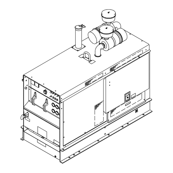
Page 21: Installing Precleaners, Exhaust Pipe, And Rain Cap
4-3. Installing Precleaners, Exhaust Pipe, And Rain Cap Y Stop engine and let cool. Y Do not blow exhaust toward air cleaner or air intake. Remove rear, left side panel. Air Cleaner Precleaner Remove tape from air cleaner openings. Install precleaners on air cleaners. -
Page 22: Connecting To Weld Output Terminals
4-5. Connecting To Weld Output Terminals Access Door Work Weld Output Terminal Tools Needed: Electrode Weld Output Terminal 3/8, 3/4 in Location of Terminals Torch Cable Adapter Adapter connects power and water to torch and cooling system or drain. Y Use only a proper torch cable adapter positioned so it does not hit frame, hardware, or door during operation. -
Page 23: Installing Ether Cylinder (Optional Ether Starting Aid)
4-7. Installing Ether Cylinder (Optional Ether Starting Aid) Y Stop engine. Y Improper handling or expo- sure to ether can harm your health. Follow manufactur- er’s safety instructions on cylinder. Y Do not use Ether Starting Aid while engine is running. Open side door(s). -
Page 24: Terminal Strip 3T Connections
4-9. Terminal Strip 3T Connections Y Stop engine. If remote control plug does not fit in receptacle RC3, wire cord directly to terminal strip 3T. Y Do not connect to Remote 14 receptacle RC3 and terminal strip 3T at the same time. Use only one remote control method. - Page 25 Notes OM-478 Page 21...
-
Page 26: Section 5 − Operating The Welding Generator
SECTION 5 − OPERATING THE WELDING GENERATOR 5-1. Front Panel Controls (See Section 5-2) ST-184 780-C / Ref. ST-121 578-F OM-478 Page 22... -
Page 27: Description Of Standard Controls (See Section 5-1)
5-2. Description Of Standard Controls (See Section 5-1) For front panel control, place switch in Panel 17 Air Tank Moisture Drain Control This unit has a max OCV control circuit position. For remote control, place switch in Before starting engine each day, pull control that resets the Amperage/Voltage Con- Remote position and connect remote control out to drain moisture from air tank. -
Page 28: Example Of Remote Amperage Control
5-3. Example Of Remote Amperage Control In Example: Min = 90 A DC/CC Percentage of Range = 50 % Max = 140 A DC/CC (50% of 90 to 190) Set Switches Set Polarity Set Range Set Percentage Min (90 A DC/CC) Max (140 A DC/CC) Adjust Remote Control Ref. -
Page 29: Section 6 − Operating Auxiliary Equipment
SECTION 6 − OPERATING AUXILIARY EQUIPMENT 6-1. 120 Volt GFCI Duplex Receptacles 120 V 15 A AC GFCI Receptacle GFCI1 120 V 15 A AC GFCI Receptacle GFCI2 Receptacles supply 60 Hz single- phase power at weld/power speed. Circuit Breaker CB1 Circuit Breaker CB2 CB1 protects GFCI1 and CB2 pro- tects GFCI2 from overload. -
Page 30: Optional 5 Kva/Kw Power Plant Receptacles
6-3. Optional 5 kVA/kW Power Plant Receptacles 240 V 13 A AC Duplex Receptacle RC1 120 V 15 A AC GFCI Receptacle GFCI2 Single-Phase Power Receptacles RC1 and GFCI2 supply 60 Hz sing- le-phase power at weld/power speed. Circuit Breaker CB1 And CB2 120V CB1 and CB2 protect RC1 from overload. - Page 31 6-4. Connecting Auxiliary Power Plant Y Stop engine. Y Power and weld outputs are live at the same time. Discon- nect or insulate unused cables. Have qualified person install according to circuit diagram and Section 12 − Auxiliary Power Guide- lines.
-
Page 32: Section 7 − Operating Optional Battery Charger
SECTION 7 − OPERATING OPTIONAL BATTERY CHARGER NOTE Follow jump starting procedure to quickly start equipment having a weak or dead battery. Follow charging procedure to trickle-charge a battery. 7-1. Jump Start/Battery Charge Cable Connections Y Stop engine. Y Do not charge or jump start a battery which has loose ter- minals or one showing dam- age such as a cracked case... -
Page 33: Jump Start/Battery Charge Controls
7-2. Jump Start/Battery Charge Controls Output Selector Switch Y Do not switch under load. Use switch to select weld or battery charge/jump start output. Output automatically stops when terminal voltage is 15 to 25 percent above required battery voltage. Move switch to weld position when done charging/jump starting. -
Page 34: Battery Charging Procedure
7-4. Battery Charging Procedure In Example: Battery Voltage = 12 Volts Battery CCA Rating = 500 Charge Current = 100 A (See Section 7-3) Ampere Range Setting = 90 to 190 A A/V Control Setting = 10 Stop Engine. Set Battery Voltage Switch. Set Output Selector Switch To Charge. -
Page 35: Jump Starting Procedure
7-5. Jump Starting Procedure Charge battery for 10 minutes before jump starting battery (see Section 7-4). Set Charge/Jump Start Charge Battery For 10 Set Output (Contactor) Switch To Jump Start. MInutes (See Section 7-4). Switch to Remote. Turn Off Remote Device. Press switch only while cranking en- gine of equipment... -
Page 36: Routine Maintenance
8-1. Routine Maintenance Y Stop engine before maintaining. See also Engine Manual and Mainte- nance Label. Service engine more often Recycle if used in severe conditions. engine To be done by Factory Authorized fluids. Service Agent. Check Fluid Wipe Levels. See Section 4-4. -
Page 37: Maintenance Label
8-2. Maintenance Label OM-478 Page 33... -
Page 38: Servicing Air Cleaner
8-3. Servicing Air Cleaner Y Stop engine. Y Do not run engine without air cleaner or with dirty element. Clean or replace element if dirty or damaged. Replace element yearly or after six cleanings. Dust Cap Baffle Element Plastic Fins Housing To clean air filter: Wipe off cap and housing. -
Page 39: Adjusting Engine Speed
8-5. Adjusting Engine Speed Y Stop engine. Engine speeds have been factory set and should not require adjust- ment. After tuning engine, check engine speeds with a tachometer. See table for proper no load speeds. necessary, adjust speeds as follows: Idle Speed Adjustment Throttle Solenoid Adjustment Rod... -
Page 40: Adjusting Air Pressure
8-6. Adjusting Air Pressure Governor cut-in pressure is 105 psi (724 kPa) and cut-out pressure is 125 psi (862 kPa). Cut-in and cut-out pressure values are ± 5 psi (34 kPa). Check pressure using air pressure gauge on front panel. If necessary, adjust cut-out pressure as follows: Governor Rubber Boot... -
Page 41: Overload Protection
8-7. Overload Protection Y Stop engine. If a circuit breaker or fuse opens, it usually indicates a more serious problem exists. Contact a Factory Authorized Service Agent. Circuit Breaker CB3 CB3 protects the 115 volts ac out- put to Remote 14 receptacle RC3 or terminal strip 3T. -
Page 42: Checking And Replacing Engine Belt
8-8. Checking And Replacing Engine Belt Y Stop engine. A V-belt drives the engine cooling fan and alternator. To check tightness of belt, proceed as follows: Remove rear panel and guard from engine pulley. Fan Pulley Alternator Pulley Engine Belt Position straight edge along top of 1/2 in (13 mm) pulleys. -
Page 43: Troubleshooting
8-10. Troubleshooting A. Welding Trouble Remedy No weld output. Check position of Ampere Range and Output Selector switches. Place Output/Contactor Control switch in On position, or place switch in Remote position and connect remote contactor to optional Remote 14 receptacle RC3 or terminal strip 3T (see Sections 4-8 and 4-9). Disconnect equipment from auxiliary power receptacles during start-up. - Page 44 Min or max CV weld output only. Check position of Amperage/voltage control and Amperage/Voltage Control switch. Repair or replace remote control device. Have Factory Authorized Service Agent check optional CV regulator board PC2. Tungsten electrode oxidizing and not Shield weld zone from drafts. remaining bright at end of weld.
- Page 45 Have Factory Authorized Service Agent check compressor for rated output. Pneumatic tools freeze up because of Install optional Turbo 2000 air dryer/filter kit (Miller part no. 043 249). moisture in compressed air. Induce an antifreeze solution into the air supply.
-
Page 46: Section 9 − Electrical Diagrams
SECTION 9 − ELECTRICAL DIAGRAMS Figure 9-1. Circuit Diagram For Welding Generator OM-478 Page 42... - Page 47 SD-194 053 OM-478 Page 43...
- Page 48 Figure 9-2. Circuit Diagram For Welding Generator With Optional Battery Charger OM-478 Page 44...
- Page 49 SD-194 061 OM-478 Page 45...
- Page 50 Figure 9-3. Circuit Diagram For Welding Generator With Optional 5 kVA/kW Auxiliary Power Plant OM-478 Page 46...
- Page 51 SD-194 062 OM-478 Page 47...
-
Page 52: Section 10 − Run-In Procedure
SECTION 10 − RUN-IN PROCEDURE run_in1 6/96 10-1. Wetstacking Welding Generator Run diesel engines near rated out- put during run-in period to properly seat piston rings and prevent wets- tacking. See nameplate or rating label to find rated output. Do not idle engine longer than necessary. - Page 53 10-2. Run-In Procedure Using Load Bank Y Stop engine. Y Do not touch hot exhaust pipe, engine parts, or load bank/grid. Y Keep exhaust and pipe away from flammables. Load Bank Turn all load bank switches Off. If needed, connect load bank to 115 volts ac wall receptacle or genera- tor auxiliary power receptacle.
- Page 54 10-3. Run-In Procedure Using Resistance Grid Y Stop engine. Y Do not touch hot exhaust pipe, engine parts, or load bank/grid. Y Keep exhaust and pipe away from flammables. Resistance Grid Use grid sized for generator rated output. Turn Off grid. Welding Generator Place A/V range switch in maxi- mum position, A/V control in mini-...
-
Page 55: Section 11 − Air Compressor Tables
SECTION 11 − AIR COMPRESSOR TABLES 11-1. Flow Of Free Air (CFM) Through Orifices Of Various Diameters Gauge Pressure In Orifice Diameter (in) And Free Air Flow (CFM) Receiver (lb) 1/64 1/32 3/64 1/16 3/32 3/16 0.027 0.107 0.242 0.430 0.97 1.72 3.86... - Page 56 11-2. Approximate Air Consumption (Cubic Feet) To Operate Pneumatic Equipment At 70-90 P.S.I.G. Percent Use Factor And Percent Use Factor And MISCELLANEOUS MISCELLANEOUS Compressed Air Consumption (CF) Compressed Air Consumption (CF) PORTABLE PORTABLE TOOLS TOOLS 9 sec 15 sec 21 sec 1 min 9 sec 15 sec...
-
Page 57: Section 12 − Auxiliary Power Guidelines
SECTION 12 − AUXILIARY POWER GUIDELINES 12-1. Selecting Equipment Auxiliary Power Receptacles − Neutral Bonded To Frame 3-Prong Plug From Case Grounded Equipment 2-Prong Plug From Double Insulated Equipment Be sure equipment has this symbol and/or wording. aux_pwr 12/96 − Ref. ST-159 730 / ST-800 577 12-2. - Page 58 12-3. Grounding When Supplying Building Systems Equipment Grounding Terminal Grounding Cable GND/PE Use #10 AWG or larger insulated copper wire. Ground Device Y Ground generator to system earth ground if supplying power to a premises (home, shop, farm) wiring system. Use ground device as stated in electrical codes.
- Page 59 12-5. Approximate Power Requirements For Industrial Motors Industrial Motors Rating Starting Watts Running Watts Split Phase 1/8 HP 1/6 HP 1225 1/4 HP 1600 1/3 HP 2100 1/2 HP 3175 Capacitor Start-Induction Run 1/3 HP 2020 1/2 HP 3075 3/4 HP 4500 1400 1 HP...
- Page 60 12-7. Approximate Power Requirements For Contractor Equipment Contractor Rating Starting Watts Running Watts Hand Drill 1/4 in 3/8 in 1/2 in Circular Saw 6-1/2 in 7-1/4 in 8-1/4 in 1400 1400 Table Saw 9 in 4500 1500 10 in 6300 1800 Band Saw 14 in...
- Page 61 12-8. Power Required To Start Motor Motor Start Code AC MOTOR Running Amperage VOLTS AMPS Motor HP CODE Motor Voltage PHASE To find starting amperage: Step 1: Find code and use table to find kVA/HP. If code is not listed, multiply running amperage by six to find starting amperage.
- Page 62 12-10. Typical Connections To Supply Standby Power Power Company Service Meter Main and Branch Overcurrent Protection Double-Pole, Double-Throw Transfer Switch Obtain and install correct switch. Switch rating must be same as or Customer-supplied equipment is required if greater than the branch overcurrent generator is to supply standby power during protection.
- Page 63 12-11. Selecting Extension Cord (Use Shortest Cord Possible) Cord Lengths for 120 Volt Loads Y If unit does not have GFCI receptacles, use GFCI-protected extension cord. Maximum Allowable Cord Length in ft (m) for Conductor Size (AWG)* Current Load (Watts) (Amperes) 350 (106) 225 (68)
- Page 64 SECTION 13 − SELECTING AND PREPARING TUNGSTEN ELECTRODE gtaw 7/97 NOTE For additional information, see your distributor for a handbook on the Gas Tungsten Arc Welding (GTAW) process.Wear clean gloves to prevent contamination of tungsten electrode. 13-1. Selecting Tungsten Electrode ♦...
- Page 65 13-2. Preparing Tungsten For AC Or DC Electrode Positive (DCEP) Welding Tungsten Electrode Balled End Y Understand follow safety symbols at start of Section 14-1 before pre- paring tungsten. Ball end of tungsten before welding 1-1/2 Times by applying either an ac amperage Electrode Diameter slightly higher than what is recom- mended for a given electrode diam-...
-
Page 66: Section 14 − Guidelines For Tig Welding (Gtaw)
SECTION 14 − GUIDELINES FOR TIG WELDING (GTAW) 14-1. Positioning The Torch Y Weld current can damage electronic parts in vehicles. Disconnect both battery cables before welding on a vehicle. Place work clamp as close to the weld as possible. Workpiece Make sure workpiece is clean before welding. - Page 67 14-3. Positioning Torch Tungsten For Various Weld Joints ° Butt Weld And Stringer Bead ° ° ° “T” Joint ° ° ° ° Lap Joint ° ° ° ° Corner Joint ° ° ST-162 003 / S-0792 OM-478 Page 63...
-
Page 68: Section 15 − Parts List
SECTION 15 − PARTS LIST Hardware is common and not available unless listed. Figure 15-1. Main Assembly (Part 1 Of 2) OM-478 Page 64... - Page 69 Item Dia. Part Mkgs. Description Quantity Figure 15-1. Main Assembly (Part 1 Of 2) ... 186 907 REACTOR ............
- Page 70 Item Dia. Part Mkgs. Description Quantity Figure 15-1. Main Assembly (Part 1 Of 2) (Continued) ....159 012 HOSE, oil drain 11.000 3/4 swivel fem 1/2MNPT .
- Page 71 Item Dia. Part Mkgs. Description Quantity Figure 15-1. Main Assembly (Part 1 Of 2) (Continued) ....149 541 HOLDER, fuse crtg 60A 250V ........
- Page 72 Hardware is common and not available unless listed. Figure 15-2. Main Assembly (Part 2 of 2) OM-478 Page 68...
- Page 73 Item Dia. Part Mkgs. Description Quantity Figure 15-2. Main Assembly (Part 2 Of 2) (Continued) ....138 098 HOSE, sst 20.750 lg 3/4NPT M ftg & 3/4NPT M inv .
- Page 74 Hardware is common and not available unless listed. ST-121 288-D Figure 15-3. Panel, Front w/Components OM-478 Page 70...
- Page 75 Item Dia. Part Mkgs. Description Quantity Figure 15-3. Panel, Front w/Components (Fig 15-1 Item 84) ....086 706 SPACER, range switch ..........
- Page 76 Item Dia. Part Mkgs. Description Quantity Figure 15-4. Panel, Front Lower w/Components (Fig 15-1 Item 85) ....039 047 TERMINAL, pwr output (consisting of) ....... .
- Page 77 Item Dia. Part Mkgs. Description Quantity Figure 15-4. Panel, Front Lower w/Components (Fig 15-1 Item 85) (Continued) ..PC30 150 415 CIRCUIT CARD, connector .........
- Page 78 Hardware is common and not available unless listed. ST-140 459-A Figure 15-5. Control Box OM-478 Page 74...
- Page 79 Item Dia. Part Mkgs. Description Quantity Figure 15-5. Control Box (Fig 15-1 Item 71) ....129 939 . . . BLOCK, term 10A 19P .
- Page 80 Hardware is common and not available unless listed. Ref. ST-143 803-B Figure 15-6. Compressor, Air OM-478 Page 76...
- Page 81 Item Part Description Quantity Figure 15-6. Compressor, Air ..066 133 HOUSING INSERT ............
- Page 82 Item Part Description Quantity Figure 15-7. Generator (Fig 15-2 Item 54) ..173 066 BRACKET, mtg brush holder ..........
- Page 83 Notes...
- Page 84 Notes...
- Page 85 Effective January 1, 1999 (Equipment with a serial number preface of KK" or newer) Warranty Questions? This limited warranty supersedes all previous Miller warranties and is exclusive with no other guarantees or warranties expressed or implied. Call LIMITED WARRANTY − Subject to the terms and conditions APT, ZIPCUT &...
- Page 86 File a claim for loss or damage during Contact the Delivering Carrier for: shipment. For assistance in filing or settling claims, contact your distributor and/or equipment manufacturer’s Transportation Department. PRINTED IN USA 1999 Miller Electric Mfg. Co. 7/99...
Need help?
Do you have a question about the Air Pak and is the answer not in the manual?
Questions and answers