Table of Contents
Advertisement
R
KOBALT is a registered trademark of LF,
LLC. All Rights Reserved.
NOTICE: On the nameplate of the machine you will find the serial number and MFG date code of the
unit. Please record these numbers on this manual cover for future service reference.
ATTACH YOUR RECEIPT HERE
Serial Number
Questions, problems, missing parts? Before returning to your retailer, call our
customer service department at 1-888-3KOBALT (1-888-356-2258), 8 a.m. - 8 p.m., EST,
Monday - Friday.
R
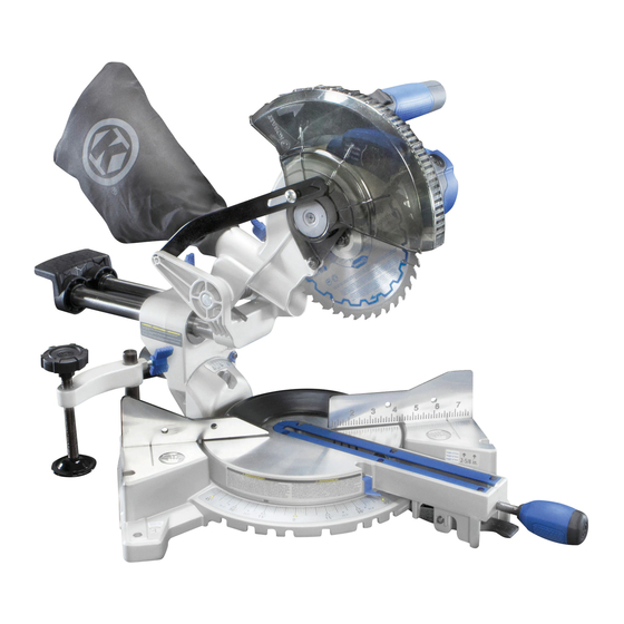
COMPOUND MITER SAW
Purchase Date
1
7-1/4 IN. SLIDING
WITH LASER GUIDE
ITEM #0358937
MODEL #SM1850LW
Français p. 45
Español p. 89
Advertisement
Table of Contents

Related Manuals for Kobalt SM1850LW


Summary of Contents for Kobalt SM1850LW
- Page 1 ITEM #0358937 7-1/4 IN. SLIDING COMPOUND MITER SAW KOBALT is a registered trademark of LF, LLC. All Rights Reserved. WITH LASER GUIDE MODEL #SM1850LW Français p. 45 Español p. 89 NOTICE: On the nameplate of the machine you will find the serial number and MFG date code of the unit.
-
Page 2: Table Of Contents
TABLE OF CONTENTS Product Specifications........................Package Contents..........................Safety Information..........................Preparation............................Assembly Instructions........................Adjustment Instructions........................Operating Instructions........................Crown Moulding Chart........................Care and Maintenance........................Troubleshooting..........................Warranty............................Replacement Parts List and Exploded Views................... PRODUCT SPECIFICATIONS MOTOR CUTTING CAPACITY Power Source 9A, 120V A/C, 60 Hz Crosscut 2 in. -
Page 3: Package Contents
PACKAGE CONTENTS UNPACKING YOUR MITER SAW WARNING: To avoid injury from unexpected starting or electrical shock, do not plug the power cord into a source of power during unpacking and assembly. The cord must remain unplugged whenever you are adjusting/assembling the saw. 1. -
Page 4: Safety Information
SAFETY INFORMATION GENERAL SAFETY INFORMATION PROPOSITION 65 WARNING Some dust created by power sanding, sawing, grinding, drilling and other construction activities contains chemicals known to the State of California to cause cancer, birth defects or other reproductive harm. Some examples of these chemicals are: ●... - Page 5 SAFETY INFORMATION POWER TOOL SAFETY Please read and understand this entire manual before attempting to assemble, operate or install the product. These safety instructions are not meant to cover every possible condition that could occur. GENERAL SAFETY INSTRUCTIONS ● LEARN the tool’s application, limitations and possible hazards. ●...
- Page 6 ● MAINTAIN TOOLS WITH CARE. Keep tools sharp and clean for best and safest performance. Follow instructions for lubricating and changing accessories. ● DIRECTION OF FEED. Feed work into a blade or cutter against the direction of rotation of the blade or cutter.
- Page 7 ● DISCONNECT the saw from the power source and clean the machine when finished using. ● SHOULD any part of your miter saw become missing, damaged, fail in any way or any electrical component fail to perform properly, shut off the switch and remove the plug from the power supply outlet.
- Page 8 SAFETY INFORMATION ELECTRICAL SPECIFICATIONS AND SAFETY CAUTION: POWER SUPPLY AND MOTOR The A/C motor used in this saw is a universal, nonreversible type. See “MOTOR” in the “PRODUCT SPECIFICATIONS” section on page 2. To avoid electrical hazards, fire hazards or damage to the tool, use proper circuit protection. Your saw is wired at the factory for 120V operation.
- Page 9 GUIDELINES FOR EXTENSION CORDS When using an extension cord, be sure to use one heavy enough to carry the current your product will draw. An undersized cord will cause a drop in line voltage, resulting in loss of power and overheating. The table below shows the correct size to use depending on cord length and nameplate ampere rating.
-
Page 10: Preparation
PREPARATION Before beginning assembly or operation of the product, make sure all parts are present. Compare parts with package contents list and diagram on page 3. If any part is missing or damaged, do not attempt to assemble, install or operate the product. Estimated Assembly Time: 10 minutes Tools Required for Assembly (included): Blade Wrench Tools Required for Assembly (not included): Adjustable Wrench, 2 mm Hex Wrench, 8 mm Hex... - Page 11 KNOW YOUR MITER SAW Safety Lock Switch Handle Upper Blade Guard Dust Bag Laser Guide Blade Base Hold-Down Clamp Table Insert Fence Hand Hold for Positive Miter Stop Transportation Positive Miter Stop Mounting Hole Locking Lever ON/OFF Trigger Switch Blade Wrench Motor Brush Arbor Lock Button Motor...
-
Page 12: Assembly Instructions
ASSEMBLY INSTRUCTIONS WARNING: To avoid injury, do not connect this miter saw to a power source until it is completely assembled and adjusted and you have read and understood the operator’s manual. INSTALLING THE MITER HANDLE (FIG. 1) ● Thread the miter handle (E) into the hole located at the front of the miter saw (A). - Page 13 INSTALLING THE HOLD-DOWN CLAMP (FIG. 3) NOTE: There are two mounting holes for the hold- down clamp. These are located just behind the fence on the left and right side of the base. ● Loosen the screw with a Phillips screwdriver. Mounting holes ●...
-
Page 14: Adjustment Instructions
ADJUSTMENT INSTRUCTIONS UNLOCKING THE SLIDE CARRIAGE (FIG. 5) ● After removing the saw from the carton, loosen the slide carriage lock knob (1). When transporting or storing the miter saw, the slide carriage should always be locked in position. The slide carriage lock knob (1) is located on the right side of the slide carriage. - Page 15 REMOVING AND INSTALLING THE TABLE INSERT (FIG. 7) NOTE: The miter saw comes with the table inserts already installed. These instructions are for replacing or adjusting either insert side. WARNING To avoid injury: ● Always unplug the saw to avoid accidental starting.
- Page 16 MOUNTING THE MITER SAW (FIG. 8, 9, 10) WARNING To avoid injury from unexpected saw movement: ● Disconnect the power cord from the outlet and lock the cutting head in the lower position using the stop latch. ● Lock the slide carriage in place by tightening the slide carriage lock knob.
-
Page 17: Removing Blade
REMOVING AND INSTALLING THE BLADE WARNING: Only use a 7-1/4 in. diameter blade. To avoid injury from an accidental start, make sure the switch is in the OFF position and the plug is not connected to the power source outlet. REMOVING (FIG. - Page 18 INSTALLING BLADE (FIG. 11, 12, 13) Unplug the miter saw before changing/installing the blade. ● Install a 7-1/4 in. blade with a 5/8 in. arbor, making sure the rotation arrow on the blade matches the clockwise rotation arrow on the upper guard.
- Page 19 BEVEL STOP ADJUSTMENT (FIG. 14, 15, 16) WARNING: To avoid injury from an accidental start, make sure the switch is in the OFF position and the plug is not connected to the power source outlet. 90° (0°) Bevel Adjustment (FIG. 14): ●...
- Page 20 MITER SCALE (FIG. 17) The sliding compound miter saw scale can be easily read, showing miter angles from 0° to 45° to the left, and 0° to 45° to the right. The miter saw table has nine of the most common angle settings with positive stops at 0°, 15°, 22.5°, 31.6°, and 45°.
- Page 21 SETTING CUTTING DEPTH (FIG. 19) The depth of cut can be preset for even and repetitive shallow cuts. ● Adjust the cutting head down until the teeth of the blade are at the desired depth. ● While holding the upper arm in that position, turn the stop knob (1) until it touches the stop plate (2).
- Page 22 DANGER: AVOID DIRECT EYE CONTACT ● A red laser line is radiated when the laser guide switch is turned on. Avoid direct eye contact. Always unplug the miter saw from power source before making any adjustments. Puissance à Ce produit est conforme aux normes 21CFR 1040.10 et 1040.11 las normas ●...
-
Page 23: Operating Instructions
OPERATING INSTRUCTIONS BEFORE USING THE MITER SAW WARNING: To avoid mistakes that could cause serious, permanent injury, do not plug the tool in until the following steps are completed: ● Completely assemble and adjust the saw, following the instructions (SEE ASSEMBLY AND ADJUSTMENTS SECTIONS). - Page 24 KEEP YOUR WORK AREA CLEAN Cluttered areas and benches invite accidents. WARNING: To avoid burns or other fire damage, never use the miter saw near flammable liquids, vapors or gases. ● Plan ahead to protect your eyes, hands, face and ears. ●...
- Page 25 Never cut freehand: ● Brace your workpiece firmly against the fence and table stop so it will not rock or twist during the cut. ● Make sure there is no debris between the workpiece and the table or fence. Make sure there are no gaps between the workpiece, fence and table that will let the workpiece shift after it is cut.
- Page 26 BODY AND HAND POSITION (FIG. 23) WARNING Never place hands near the cutting area. Proper positioning of your body and hands when operating the miter saw will make cutting easier and safer. Keep children away. Keep all visitors at a safe distance from the miter saw.
- Page 27 BASIC SAW OPERATIONS TURNING THE LASER GUIDE ON (FIG. 24) Press the on/off rocker switch (1) to “ON” position to activate the laser guide. TURNING THE SAW ON (FIG. 24) This miter saw is equipped with an ON/OFF trigger switch (2). With the safety lock (3) pressed, squeeze the trigger switch to turn the miter saw ON.
- Page 28 BEFORE LEAVING THE SAW ● Never leave tool running unattended. Turn power OFF. Wait for all moving parts to stop. ● Make workshop childproof. Lock the shop. Disconnect master switches. Store tool away from children and other unqualified users. WARNING: To avoid injury from materials being thrown, always unplug the saw to avoid accidental starting and remove small pieces of material from the table cavity.
- Page 29 COMPOUND CUT (FIG. 28) A compound cut is the combination of a miter and a bevel cut simultaneously. ● Loosen the bevel lock handle (1) and position the cutting head at the desired bevel position. Lock the bevel lock handle (1). ●...
-
Page 30: Cutting Grooves
CUTTING GROOVES (FIG. 31) WARNING: DO NOT USE A DADO BLADE, use only the standard saw blade for this operation. Cut these ● Mark lines to identify the width and depth of grooves the desired cut on the workpiece and put the with saw workpiece on the table and aim the inside tip of the blade at the line. - Page 31 CUTTING BASE MOULDING (FIG. 34) Base mouldings and many other mouldings can be cut on a compound miter saw. The setup of the saw depends on moulding characteristics and Workpiece applications, as shown. Perform practice cuts on Workpiece scrap material to achieve best results: ●...
- Page 32 Bevel/Miter Settings BEVEL MITER TYPE OF CUT SETTING SETTING Inside corner - Left side 1. Position top of moulding against fence. 33.9° 31.6° Right 2. Miter table set at RIGHT 31.6°. 3. LEFT side is finished piece. Inside corner - Right side 1.
-
Page 33: Crown Moulding Chart
CROWN MOULDING CHART Compound Miter Saw 52/38° Crown 45/45° Crown Miter and Bevel Angle Settings Moulding Moulding Angle Wall to Crown Moulding Angle Miter Bevel Miter Bevel Between 52/38° Crown 45/45° Crown Setting Setting Setting Setting Walls Moulding Moulding 18.84 22.46 21.40 20.05... -
Page 34: Care And Maintenance
CARE AND MAINTENANCE WARNING ● To avoid fire or toxic reaction, never use gasoline, naphtha acetone, lacquer thinner or similar highly volatile solvents to clean the miter saw. ● To avoid injury from unexpected starting or electrical shock, unplug the power cord before working on the saw. - Page 35 SAWDUST Periodically, sawdust will accumulate under the worktable and base. This could cause difficulty in the Central pivot of movement of the worktable when setting up a miter plastic guard cut. Frequently blow out or vacuum up the sawdust. CAUTION If blowing sawdust, wear proper eye protection to keep debris from blowing into eyes.
-
Page 36: Troubleshooting
TROUBLESHOOTING WARNING To avoid injury from accidental starting, always ensure switch is in the OFF position and unplug the tool before moving, replacing the blade or making adjustments. TROUBLESHOOTING – MOTOR PROBLEM POSSIBLE CAUSE CORRECTIVE ACTION Blade does not 1. Motor brushes not sealed or lightly 1. -
Page 37: Warranty
WARRANTY The manufacturer will offer replacement parts for this product which under normal usage have proven to be defective in their manufacture or workmanship for a period of THREE (3) years from the date of initial retail purchase. This warranty is valid only to the original purchaser. This warranty is not transferable and does not cover any parts that have been subjected to misuse, abuse, alteration, overload, accident or normal wear of moving parts. -
Page 38: Replacement Parts List And Exploded Views
REPLACEMENT PARTS LIST - SAW (PART A) I.D. Description Size Q’ty I.D. Description Size Q’ty X4NP MOTOR ASS’Y 1 X4PY DUST BAG X4P0 CR. RE. PAN HD. SCREW M5*55 1 X4PZ LASER COVER X4P1 BATTERY (AAA) 2 X4Q0 LASER LABEL (LEFT) X4P2 BATTERY BOX 1 X4Q1 CR. - Page 39 EXPLODED VIEW - SAW (PART A) X4R0 X4QZ X4R0 X4R1 X4R2 X4R7 X4S7 X4R6 X4R5 X4R7 X4R8 X4S6 X4PH X4R3 X4R9 X4RQ X4PG X4PY X4PF X4Q8 X4PE X4Q7 X4Q6 X4RQ X4RQ X4SX X4RA X4NP X4P0 X4S6 X4QL X4RC X4PD X4RD X4PC X4Q1 X4PP...
- Page 40 REPLACEMENT PARTS LIST - SAW (PART B) I.D. Description Size Q’ty I.D. Description Size Q’ty X4NQ SWIVEL SUPPORT ASS’Y X4S8 LOCATION PLATE X4NR VISE ASS’Y X4SB HEX. HD. BOLT M10*65 X4NS OPERATOR’S MANUAL X4SD HEX. NUT X4NU WING SCREW M6*18 X4SE TILTING SCALE X4Q6 INNER HEX.
- Page 41 EXPLODED VIEW - SAW (PART B) X4RN X4RP X4RQ X4RR X4SV X4RG X4RS X4RH X4RT X4RJ X4S5 X4RU X4RK X4RV X4S3 X4S4 X4RL X4RM X4RW X4S6 X4NS X4S7 X4NQ X4S8 X4SB X4RX X4S2 X4SD X4RY X4SH X4SE X4RZ X4SF X4SJ X4SG X4SK X4S0...
- Page 42 REPLACEMENT PARTS LIST - MOTOR I.D. Description Size Q’ty X4PJ FLAT WASHER φ5 X4PK SPRING WASHER φ5 X4PL CR. RE. PAN HD. SCREW M5*30 X4PM BEARING X4PN SPRING X4Q3 X4Q4 ARBOR LOCK X4Q5 SHELL X4Q9 STOPPING WIND PLATE X4QA ARMATURE ASS’Y X4QB BEARING X4QC...
- Page 43 EXPLODED VIEW - MOTOR X4QK X4QH X4QJ X4QG X4QF X4QE X4QD X4QC X4QB X4PL X4PK X4PJ X4QA X4Q9 X4Q5 X4Q4 X4Q3 X4PM X4PN X4QM X4QN X4QR X4QP X4QS X4QQ X4QT X4QU X4QV X4PK X4QX Printed in China...
- Page 44 PAGE INTENTIONALLY LEFT BLANK...
Need help?
Do you have a question about the SM1850LW and is the answer not in the manual?
Questions and answers