Table of Contents
Advertisement
ATTACH YOUR RECEIPT HERE
Serial Number
Questions, problems, missing parts? Before returning to your retailer, call our
customer service department at 1-888-3KOBALT (1-888-356-2258), 8 a.m. - 8 p.m.,
EST, Monday - Friday.
PH18528
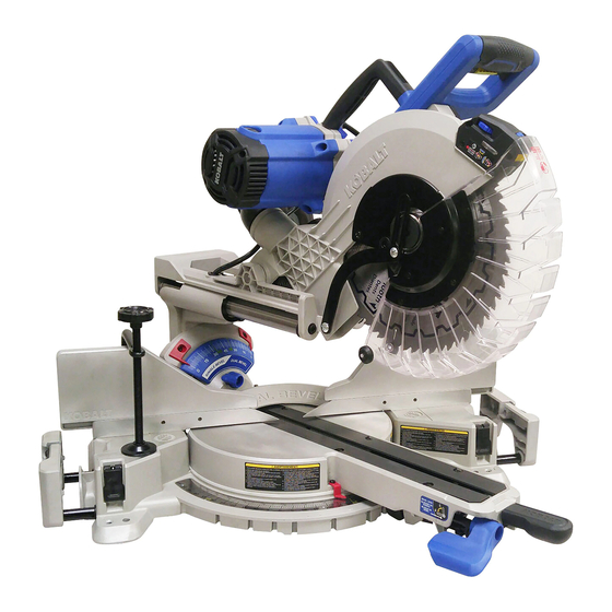
12-IN COMPACT SLIDING
DUAL-BEVEL MITER SAW
MFG Date
1
MODEL #SM3017LW / #1413795
Purchase Date
C
US
Español p. 45
Advertisement
Table of Contents

Related Manuals for Kobalt SM3017LW


Summary of Contents for Kobalt SM3017LW
- Page 1 12-IN COMPACT SLIDING DUAL-BEVEL MITER SAW MODEL #SM3017LW / #1413795 Español p. 45 ATTACH YOUR RECEIPT HERE Serial Number MFG Date Purchase Date Questions, problems, missing parts? Before returning to your retailer, call our customer service department at 1-888-3KOBALT (1-888-356-2258), 8 a.m. - 8 p.m., EST, Monday - Friday.
-
Page 2: Table Of Contents
TABLE OF CONTENTS Package Contents ......................General Power Tool Safety Warnings ................Eletrical Safety Information ....................Preparation ........................Assembly Instructions ....................... Adjustment Instructions ..................... Operating Instructions ....................... Crown Moulding Chart ...................... Care and Maintenance ..................... Troubleshooting ........................ Replacement Parts List ..................... Warranty .......................... -
Page 3: Package Contents
PACKAGE CONTENTS UNPACKING YOUR MITER SAW WARNING To avoid injury from unexpected starting or electrical shock, do not plug the power cord into a source of power during unpacking and assembly. The cord must remain unplugged whenever you are adjusting/assembling the saw. 1. -
Page 4: General Power Tool Safety Warnings
GENERAL POWER TOOL SAFETY WARNINGS WARNING provided with this power tool. Failure to follow all instructions listed below may result in electric Save all warnings and instructions for future reference. The term "power tool" in the warnings refers to your mains-operated (corded) power tool or battery-operated (cordless) power tool. - Page 5 Protective equipment such as dust mask, non-skid safety shoes, hard hat, or hearing protection used for appropriate conditions will reduce personal injuries. Prevent unintentional starting. Ensure the switch is in the off-position before connecting to power source and/or battery pack, picking up or carrying the tool. switch on invites accidents.
- Page 6 Use the power tool, accessories and tool bits etc. in accordance with these instructions, taking into account the working conditions and the work to be performed. Use of the power tool for operations different from those intended could result in a hazardous situation. Keep handles and grasping surfaces dry, clean and free from oil and grease.
- Page 7 Do not use the saw until the table is clear of all tools, wood scraps, etc., except for the workpiece. Small debris or loose pieces of wood or other objects that contact the revolving blade can be thrown with high speed. Cut only one workpiece at a time.
- Page 8 PROPOSITION 65 WARNING WARNING: Drilling, sawing, sanding or machining wood products can expose you to wood dust, a substance known to the State of California to cause cancer, Avoid inhaling wood dust or use a dust mask or other safeguards for personal protection. For more information go to: www.P65Warnings.ca.gov/wood Some examples of these chemicals are: Lead from lead-based paints,...
- Page 9 ELECTRICAL SAFETY INFORMATION ELECTRICAL SPECIFICATIONS AND SAFETY : POWER SUPPLY AND MOTOR CAUTION The AC motor used in this saw is a universal, nonreversible type. See “MOTOR” in the “PRODUCT SPECIFICATIONS” section on page 2. protection. Your saw is wired at the factory for 120V operation. Connect to a 120V, 15A circuit and use a 20A time-delay fuse or circuit breaker.
- Page 10 FUSES may “blow” or circuit breakers may trip frequently if: MOTOR is overloaded – overloading can occur if you feed too rapidly or make too many starts/stops in a short time. LINE VOLTAGE is more than 10% above or below the nameplate voltage rating. For nameplate.
-
Page 11: Preparation
PREPARATION Before beginning assembly or operation of the product, make sure all parts are present. Compare parts with package contents list and diagram on page 3. If any part is missing or damaged, do not attempt to assemble, install or operate the product. Estimated Assembly Time: 10 minutes Tools needed to remove or install blade (included): Blade Wrench Tools Required for Adjustment (not included): Adjustable Wrench, 5 mm Hex Wrench,... - Page 12 KNOW YOUR MITER SAW Carrying Handle Switch Handle Laser Vertical Motor Adjustment Knob Laser Horizontal Adjustment Knob Right Bevel Detent Pin Hold-down Clamp Right Extension Wing Sliding Fence Left Extension Wing Extension Locking Lever Miter Angle Pointer Miter Lock Handle Arbor Lock Button Hold-down Latch Laser Guide...
-
Page 13: Assembly Instructions
ASSEMBLY INSTRUCTIONS WARNING To avoid injury, do not connect this miter saw to a power source until it is completely assembled and adjusted and you have read and understood the operator’s manual. UNLOCKING THE SLIDE CARRIAGE (FIG. 1) The slide carriage lock knob (1) is located on the right side of the slide carriage. - Page 14 INSTALLING THE HOLD-DOWN CLAMP (FIG. 4) NOTE: There are two mounting holes for the hold-down clamp. These are located just behind the fence on the left and right side of the base. Loosen the lock knob (1) behind the fence. desired mounting holes.
-
Page 15: Adjustment Instructions
ADJUSTMENT INSTRUCTIONS REMOVING AND INSTALLING THE TABLE INSERTS (FIG. 5) NOTE: The miter saw comes with the table inserts already installed. These instructions are for replacing or adjusting either insert side. To avoid injury: Always unplug the saw to avoid accidental starting. - Page 16 MOUNTING THE MITER SAW (FIG. 6, 7, 8) WARNING To avoid injury from unexpected saw movement: Disconnect the power cord from the outlet and lock the cutting head in the lower position using the hold-down latch. Lock the slide carriage in place by tightening the slide carriage lock knob.
- Page 17 REMOVING AND INSTALLING THE BLADE WARNING Use only a saw blade diameter in accordance with the markings on the saw. Only use a 12 in. diameter blade with a 1 in. arbor hole and an operating speed of more than 4,200 RPM. Do not use blades with deep guard, causing damage to the machine and/or serious injury.
- Page 18 INSTALLING THE BLADE (FIG. 9, 10, 11, 12, 13) Unplug the miter saw before changing/installing the blade. Install a 12 in. blade with a 1 in arbor, using the provided blade insert sleeve (11) to match the 5/8 in motor arbor. Make sure the rotation arrow on the blade matches the clockwise rotation arrow on the upper guard.
- Page 19 UNLOCKING AND LOCKING THE CUTTING HEAD (FIG. 14) Unlocking the cutting head: To raise the cutter head from its storage/ transport position, push down slightly on the switch handle (1). Pull out the hold-down latch (2). Allow the cutting head to rise to the up position. Locking the cutting head: When transporting or storing the miter saw, the cutting head should always be locked in the down...
- Page 20 Repeat above steps if further adjustment is needed. Tighten bevel lock handle (1) when alignment is achieved. 90° Bevel Pointers Adjustment (Fig. 16): When the blade is exactly 90° to the table, loosen the bevel indicator screws (1) using a Phillips screwdriver.
- Page 21 Left/Right 48° Bevel Adjustment (Fig. 17, 18) : Turn the left bevel detent block (1) to 48° position. Adjust the left and right side 48° bevel angle using the same instructions given above for adjusting the 45° bevel. MITER SCALE (FIG. 19) The sliding compound miter saw scale can be easily read, showing miter angles from 0°...
- Page 22 ADJUSTING FENCE SQUARENESS (FIG. 20) Remove both sliding fences (1) by loosening the sliding fence lock knobs (2). Lower the cutting arm and lock in position. Loosen the four fence locking bolts (3) using a 5 mm hex wrench. Using a square (4), lay the heel of the square against the blade and the ruler against the fence (1) as shown.
- Page 23 SETTING CUTTING DEPTH (FIG. 22) The depth of cut can be preset for even and repetitive shallow cuts. Adjust the cutting head down until the teeth of the blade are at the desired depth. While holding the upper arm in that position, turn the stop knob (1) until it touches the stop plate (2).
- Page 24 AVOID DIRECT EYE CONTACT A laser is radiated when the laser guide is turned on. Avoid direct eye contact. Laser Warning Label: LASER RADIATION DO NOT VIEW DIRECTLY WITH OPTICAL INSTRUMENTS CLASS 1M LASER PRODUCT <0.39MW, 400-700NM, CW, Acc.IEC 60825-1. Laser Aperture Label.
- Page 25 A. Checking Laser Line Alignment (Fig. 25, 27) Cutting line running across the top and down the front of a board. This line will serve as the pattern line (Fig. 27) to adjust the laser. Place the board on the saw table. Laser line Workpiece saw blade with the pattern line.
- Page 26 B. Adjusting the Position of the Laser Line (Fig. 26, 27, 28) Front Line (Fig. 26, 27) If the laser line is angled from left to right, turn the laser vertical adjustment knob (1) counterclockwise to align the laser line parallel with pattern line.
-
Page 27: Operating Instructions
OPERATING INSTRUCTIONS BEFORE USING THE MITER SAW WARNING To avoid mistakes that could cause serious, permanent injury, do not plug the tool in until the following steps are completed: Completely assemble and adjust the saw, following the instructions (SEE ASSEMBLY AND ADJUSTMENTS SECTIONS). - Page 28 KEEP YOUR WORK AREA CLEAN Cluttered areas and benches invite accidents. WARNING gases. Plan ahead to protect your eyes, hands, face and ears. from accidental contact with moving parts, do not layout, assemble or set up work on the miter saw. Avoid accidental starting.
- Page 29 Never cut freehand: the cut. Make sure there is no debris between the workpiece and the table or fence. Make sure there are no gaps between the workpiece, fence and table that will let the workpiece shift after it is cut.
- Page 30 BODY AND HAND POSITION (FIG. 29) WARNING Never place hands near the cutting area. Proper positioning of your body and hands when operating the miter saw will make cutting easier and safer. Keep children away. Keep all visitors at a safe distance from the miter saw.
- Page 31 BASIC SAW OPERATIONS WARNING For your convenience, your saw has an electric brake. The brake is not a safety device. Never rely on it to replace the proper use of the guard on your saw. If the blade does not stop within 5 seconds, unplug the saw and follow the instructions in TROUBLESHOOTING.
- Page 32 SLIDING FENCE (FIG. 32) WARNING The sliding fence must be extended when making any bevel cut. Failure to extend the sliding fence will not allow enough space for the blade to pass through, which could result in serious injury. At extreme miter or bevel angles, the saw blade may also contact the fence.
- Page 33 BEVEL CUT (FIG. 34) WARNING The sliding fence must be extended when making any bevel cut. Failure to extend the sliding fence will not allow enough space for the blade to pass through which could result in serious injury. At extreme miter or bevel angles, the saw blade may also contact the fence.
- Page 34 SLIDE CUTTING WIDE BOARDS (FIG. 36) CAUTION Always use a work clamp to maintain control and reduce the risk of workpiece damage and personal injury. To avoid injury: Let the blade reach full speed before cutting. This will help reduce the risk of a thrown workpiece.
- Page 35 Slide the two fences into the rear position (2). Tighten the two fence locking knobs. WARNING cuts to check the path of the blade and the operation of the guards. Ensure the fence does not interfere with the action of the saw or guards. CUTTING BOWED MATERIAL (FIG.
- Page 36 WORKPIECE SUPPORT (FIG. 41) NOTE: Long pieces need extension wing support. Lift up the lock lever (1) to unlock the extension table. Slide the extension wing to desired position and push down the lock lever (1) to tighten. If the lock lever (1) is not tight enough, adjust the nuts (2) located underneath the base 1/4 turn counterclockwise.
- Page 37 CUTTING BASE MOULDING (FIG. 43) Base mouldings and many other mouldings can be cut on a compound miter saw. The setup of the saw depends on moulding characteristics and applications, as shown. Perform practice cuts on scrap material to achieve best results: Workpiece Workpiece against the fence and table.
- Page 38 NOTE: The chart below references a compound cut for crown moulding ONLY WHEN THE ANGLE BETWEEN THE WALLS EQUALS 90°. Bevel/Miter Settings BEVEL MITER TYPE OF CUT SETTING SETTING Inside corner - Left side 1. Position top of moulding against fence. 33.9°...
-
Page 39: Crown Moulding Chart
CROWN MOULDING CHART Compound Miter Saw Miter and Bevel Angle Settings Wall to Crown Moulding Angle 52/38° Crown Moulding 45/45° Crown Moulding 52/38° Crown Moulding 45/45° Crown Moulding Angle Between Miter Bevel Miter Bevel Angle Between Miter Bevel Miter Bevel Walls Setting Setting... -
Page 40: Care And Maintenance
CARE AND MAINTENANCE WARNING gasoline, naphtha, acetone, lacquer thinner or similar highly volatile solvents to clean the miter saw. To avoid injury from unexpected starting or electrical shock, unplug the power cord before working on the saw. For your safety, this saw is double insulated. Reassemble exactly to avoid electrical shock. - Page 41 SAWDUST the movement of the worktable when setting up a miter cut. Frequently blow out or vacuum up the sawdust. If blowing sawdust, wear proper eye protection to keep debris from blowing into eyes. FREE WARNING LABEL REPLACEMENT: If your warning labels become illegible or are missing, call 1-800-243-5114 for a free replacements.
-
Page 42: Troubleshooting
TROUBLESHOOTING WARNING To avoid injury from accidental starting, always ensure that the switch is in the OFF position and unplug the tool before moving, replacing the blade or making adjustments. TROUBLESHOOTING - MOTOR PROBLEM PROBLEM CAUSE CORRECTIVE ACTION Brake does not 1. -
Page 43: Replacement Parts List
REPLACEMENT PARTS LIST For replacement parts, call our customer service department at 1-888-3KOBALT, 8 a.m. - 8 p.m., EST, Monday - Friday. PART DESCRIPTION PART # Hold-down clamp 3VMS Dust bag 3YSA Blade wrench 3VJN Manual 41XE Carbon brushes (set of 2) 0QQT DISTRIBUTED BY: L G SOURCING, INC. -
Page 44: Warranty
WARRANTY The manufacturer will offer replacement parts for this product which under normal usage have proven to be defective in their manufacture or workmanship for a period of THREE (3) years from the date of initial retail purchase. This warranty is valid only to the original purchaser. This warranty is not transferable and does not cover any parts that have been subjected to misuse, abuse, alteration, overload, accident or normal wear of moving parts.
Need help?
Do you have a question about the SM3017LW and is the answer not in the manual?
Questions and answers