Table of Contents
Advertisement
Quick Links
Advertisement
Chapters
Table of Contents
Troubleshooting

Related Manuals for Suzuki AN400


Summary of Contents for Suzuki AN400
-
Page 2: General Information
FOREWORD GROUP INDEX This manual contains an introductory description on the SUZUKI AN400 and procedures for its inspec- tion/service and overhaul of its main components. GENERAL INFORMATION Other information considered as generally known is not included. Read the GENERAL INFORMATION section to... - Page 3 HOW TO USE THIS MANUAL TO LOCATE WHAT YOU ARE LOOKING FOR: 1. The text of this manual is divided into sections. 2. The section titles are listed in the GROUP INDEX. 3. Holding the manual as shown at the right will allow you to find the first page of the section easily.
- Page 4 Apply oil. Use engine oil unless other- Use engine coolant. wise specified. 99000-99032-11X Apply molybdenum oil solution. Use fork oil. (Mixture of engine oil and SUZUKI 99000-99044-10G MOLY PASTE in a ratio of 1:1) Apply SUZUKI SUPER GREASE “A”. 99000-25010 (Others) Apply or use brake fluid.
- Page 5 ABBREVIATIONS USED IN THIS MANUAL ABDC : After Bottom Dead Center : Engine Control Module : Alternating Current Engine Control Unit (ECU) : Air Cleaner, Air Cleaner Box (FI Control Unit) : American Petroleum Institute ECT Sensor : Engine Coolant Temperature ATDC : After Top Dead Center Sensor (ECTS), Water Temp.
- Page 6 MAL-Code : Malfunction Code (Diagnostic Code) : Maximum : Malfunction Indicator Lamp (LED) : Minimum : Nitrogen Oxides : Over Head Camshaft : Oil Level Switch : Oil Pressure Switch : Positive Crankcase Ventilation (Crankcase Breather) : Right Hand : Read Only Memory : Society of Automotive Engineers TO Sensor : Tip Over Sensor (TOS)
-
Page 7: Table Of Contents
CONTENTS WARNING/CAUTION/NOTE ................. 1- 2 GENERAL PRECAUTIONS ................1- 2 ’ SUZUKI AN400 ( 03-MODEL)............... 1- 4 SERIAL NUMBER LOCATION ..............1- 4 FUEL, OIL AND ENGINE COOLANT RECOMMENDATION ....... 1- 4 FUEL (FOR USA AND CANADA) ............1- 4 FUEL (FOR OTHER COUNTRIES) ............ -
Page 8: Warning/Caution/Note
GENERAL INFORMATION WARNING/CAUTION/NOTE Please read this manual and follow its instructions carefully. To emphasize special information, the symbol and the words WARNING, CAUTION and NOTE have special meanings. Pay special attention to the mes- sages highlighted by these signal words. Indicates a potential hazard that could result in death or injury. - Page 9 GENERAL INFORMATION " * If parts replacement is necessary, replace the parts with Suzuki Genuine Parts or their equiva- lent. * When removing parts that are to be reused, keep them arranged in an orderly manner so that they may be reinstalled in the proper order and orientation.
-
Page 10: Suzuki An400 ( 03-Model)
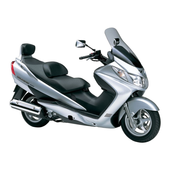
GENERAL INFORMATION SUZUKI AN400 (’03-MODEL) RIGHT SIDE LEFT SIDE • Difference between photographs and actual motorcycles depends on the markets. SERIAL NUMBER LOCATION The frame serial number or V.I.N. (Vehicle Identification Number) 1 is stamped on the right side of the frame tube. -
Page 11: Engine Oil And Transmission Oil (For Usa)
GENERAL INFORMATION ENGINE OIL AND TRANSMISSION OIL (FOR USA) SUZUKI recommends the use of SUZUKI PERFORMANCE 4 MOTOR OIL or an oil which is rated SF or SG under the API (American Pertoleum Institute) service classification. The recommended viscosity is SAE 10W-40. -
Page 12: Liquid Amount Of Water/Engine Coolant
GENERAL INFORMATION LIQUID AMOUNT OF WATER/ENGINE COOLANT Solution capacity (total): Approx. 1 300 ml (1.4/1.1 US/Imp qt) For engine coolant mixture information, refer to cooling system section, page 6-3. " Mixing of anti-freeze/engine coolant should be limited to 60%. Mixing beyond it would reduce its efficiency. -
Page 13: Break-In Procedures
GENERAL INFORMATION BREAK-IN PROCEDURES During manufacture only the best possible materials are used and all machined parts are finished to a very high standard but it is still necessary to allow the moving parts to “BREAK-IN” before subjecting the engine to maximum stresses. -
Page 14: Information Labels
GENERAL INFORMATION INFORMATION LABELS Warning safety label Engine starting label Screen warning label " Tire pressure label Fuel caution label (For E-02) Loading capacity label ID label & Information label (For E-03, 28, 33) Noise label (For E-03, 33) Front box Stick the label on the frame tube. -
Page 15: Specifications
GENERAL INFORMATION SPECIFICATIONS DIMENSIONS AND DRY MASS Overall length ................2 260 mm (89.0 in) Overall width ................760 mm (29.9 in) Overall height ................1 375 mm (54.1 in) Wheelbase ................1 590 mm (62.6 in) Ground clearance..............125 mm (4.9 in) Seat height ................ -
Page 16: Electrical
1-10 GENERAL INFORMATION ELECTRICAL Ignition type................Electronic ignition (Transistorized) Ignition timing................10 ° B.T.D.C.at 1 400 r/min Spark plug................NGK CR7E or DENSO U22ESR-N Battery..................12 V 28.8 kC (8 Ah)/10 HR Generator................Three-phase A.C.generator Main fuse ................30 A Fuse .................. -
Page 17: Country And Area Codes
GENERAL INFORMATION 1-11 COUNTRY AND AREA CODES The following codes stand for the applicable country (-ies) and area (-s). CODE COUNTRY or AREA E-02 U.K. E-03 U.S.A. (Except for California) E-19 E-28 Canada E-33 California (U.S.A.) E-54 Israel... - Page 18 PERIODIC MAINTENANCE PERIODIC MAINTENANCE CONTENTS PERIODIC MAINTENANCE SCHEDULE ............. 2- 2 PERIODIC MAINTENANCE CHART ............2- 2 LUBRICATION POINTS ................. 2- 3 MAINTENANCE AND TUNE-UP PROCEDURES ........2- 4 AIR CLEANER ..................2- 4 EXHAUST PIPE BOLT AND MUFFLER BOLT ........2- 5 VALVE CLEARANCE ................
-
Page 19: Periodic Maintenance Schedule
PERIODIC MAINTENANCE PERIODIC MAINTENANCE SCHEDULE The chart below lists the recommended intervals for all the required periodic service work necessary to keep the motorcycle operating at peak performance and economy. Mileages are expressed in terms of kilome- ters, miles and time for your convenience. NOTE: More frequent servicing may be performed on motorcycles that are used under severe conditions. -
Page 20: Lubrication Points
PERIODIC MAINTENANCE LUBRICATION POINTS Proper lubrication is important for smooth operation and long life of each working part of the motorcycle. Major lubrication points are indicated below. Combination brake lever folder Center stand pivot Side-stand pivot and spring hook and spring hook Front brake Throttle cables lever holder... -
Page 21: Maintenance And Tune-Up Procedures
PERIODIC MAINTENANCE MAINTENANCE AND TUNE-UP PROCEDURES • This section describes the servicing procedures for each item of the Periodic Maintenance requirements. AIR CLEANER Clean every 3 000 km (1 800 miles). • Remove the front trunk box cover. (!7-16) • Remove the air cleaner cover 1. •... -
Page 22: Exhaust Pipe Bolt And Muffler Bolt
PERIODIC MAINTENANCE EXHAUST PIPE BOLT AND MUFFLER BOLT Tighten initially at 1 000 km (600 miles, 1 months) and every 6 000 km (4 000 miles, 6 months) thereafter. • Remove the under cover. (!7-14) • Tighten the exhaust pipe bolts 1, exhaust pipe joint nuts 2 and muffler mounting nut 3 to the specified torque with a torque wrench. - Page 23 PERIODIC MAINTENANCE • The valve clearance specification is different for intake and Tappet screw Lock nut exhaust valves. Valve clearance adjustment must be checked and adjusted, 1) at the time of periodic inspection, 2) when Thickness gauge Rocker arm the valve mechanism is serviced, and 3) when the camshaft is disturbed by removing it for servicing.
-
Page 24: Spark Plug
PERIODIC MAINTENANCE SPARK PLUG Inspect at 6 000 km (4 000 miles, 6 months) and repla- ce every 12 000 km (7 000 miles, 12 months) thereafter. REMOVAL • Remove the left side leg shield. (!7-15) • Disconnect the spark plug cap 1 and remove the spark plug. % 09930-10121: Spark plug socket wrench set Hot type Standerd... -
Page 25: Fuel Line
PERIODIC MAINTENANCE REMOUNTING " Before using a spark plug wrench, carefeuuly turn the spark plug by finger into the threads of the cylinder head to prevent damage the aluminum threads. • Install the spark plug to the cylinder head by finger tight, and then tighten it to the specified torque. - Page 26 PERIODIC MAINTENANCE • Fit the oil drain plug 3 securely, and pour fresh oil through the oil filler. The engine will hold about 2 000 ml of oil. Use an API classification of SF or SG oil with SAE 10W-40 viscosity. # Oil drain plug: 23 N·m (2.3 kgf-m, 16.5 lb-ft) •...
-
Page 27: Final Gear Oil
2-10 PERIODIC MAINTENANCE • Install the new O-ring 3 and spring 4 to the oil filter cap. NOTE: * Before installing the oil filter cap, apply engine oil lightly to the new O-ring 3. * The triangle mark A on the oil filter cap should be positioned topward. -
Page 28: Idle Speed
PERIODIC MAINTENANCE 2-11 IDLE SPEED Inspect initially at 1 000 km (600 miles, 1 months) and every 6 000 km (4 000 miles, 6 months) thereafter. NOTE: Make this adjustment when the engine is hot. • Remove the front trunk box cover. (!7-16) •... -
Page 29: Throttle Cable Play
2-12 PERIODIC MAINTENANCE THROTTLE CABLE PLAY Inspect initially at 1 000 km (600 miles, 1 months) and every 6 000 km (4 000 miles, 6 months) thereafter. Adjust the throttle cable play A with the following three steps. First step: •... -
Page 30: Cooling Fan Filter
PERIODIC MAINTENANCE 2-13 COOLING FAN FILTER Clean every 3 000 km (1 800 miles). • Remove the left side leg shield. (!7-15) • Remove the cooling fan cover 1. • Remove the cooling fan filter 2. • Clean the fan filter. •... - Page 31 2-14 PERIODIC MAINTENANCE ENGINE COOLANT LEVEL CHECK • Keep the motorcycle upright. • Check the engine coolant level by observing the full and lower lines on the engine coolant reserve tank. F Full line L Lower line • If the level is below the lower line, remove the filler cap 1 and add engine coolant to the full line from the engine coolant reserve tank filler.
-
Page 32: Drive V-Belt Inspection
PERIODIC MAINTENANCE 2-15 AIR BLEEDING THE ENGINE COOLANT CIRCUIT • Bleed air from the air bleeder bolt 1. • Tighten the air bleeder bolt 1 to the specified torque. # Air bleeder bolt: 6 N·m (0.6 kgf-m, 4.3 lb-ft) • Add engine coolant up to the radiator inlet. •... -
Page 33: Brake System
2-16 PERIODIC MAINTENANCE BRAKE SYSTEM (BRAKE) Inspect initially at 1 000 km (600 miles, 1 months) and every 6 000 km (4 000 miles, 6 months) thereafter. (BRAKE HOSE AND BRAKE FLUID) Inspect every 6 000 km (4 000 miles, 6 months). Replace hoses every 4 years. - Page 34 PERIODIC MAINTENANCE 2-17 BRAKE PAD WEAR • The extent of brake pad wear can be checked by observing the grooved limit A on the pad. When the wear exceeds the grooved limit, replace the pads with new ones. " Replace the brake pad as a set, otherwise braking per- formance will be adversely affected.
- Page 35 2-18 PERIODIC MAINTENANCE • Connect a clear hose 1 to the air bleeder valve and insert the other end of the hose into a receptacle. • Loosen the air bleeder valve and pump the brake lever until the old brake fluid is completely out of the brake system. •...
- Page 36 PERIODIC MAINTENANCE 2-19 AIR BLEEDING THE BRAKE FLUID CIRCUIT • Air trapped in the fluid circuit acts like a cushion to absorb a large proportion of the pressure developed by the master cyl- inder and thus interferes with the full braking performance of the brake caliper.
-
Page 37: Steering
2-20 PERIODIC MAINTENANCE • Close the bleeder valve, and disconnect the clear hose. • Fill the reservoir with brake fluid to the “UPPER” line. " Handle brake fluid with care: the fluid reacts chemi- cally with paint, plastics, rubber materials and so on. AIR BLEEDING FOR THE COMBINATION BRAKE •... -
Page 38: Front Fork
PERIODIC MAINTENANCE 2-21 • Check that there is no play in the steering stem while grasping the lower fork tubes by supporting the machine so that the front wheel is off the ground, with the wheel straight ahead, and pull forward. If play is found, perform steering bearing adjustment as described in page 7-46 of this manual. -
Page 39: Tire
The standard tire fitted on this motorcycle is 110/90-13 M/C 55P for front and 130/70-13 M/C 63 P for rear. The use of tires other than those specified may cause instability. It is highly recommended to use a SUZUKI Genuine Tire. TIRE TYPE... -
Page 40: Chassis Bolt And Nut
PERIODIC MAINTENANCE 2-23 CHASSIS BOLT AND NUT Tighten initially at 1 000 km (600 miles, 1 months) and every 6 000 km (4 000 miles, 6 months) thereafter. • Check that all chassis bolts and nuts are tightened to their specified torque.(Refer to pages 2-24 for the locations of the following nuts and bolts on the motorcycle.) Item N·m... - Page 41 2-24 PERIODIC MAINTENANCE...
-
Page 42: Compression Pressure Check
PERIODIC MAINTENANCE 2-25 COMPRESSION PRESSURE CHECK • The compression of a cylinder is a good indicator of its internal condition. • The decision to overhaul the cylinder is often based on the results of a compression test. Periodic mainte- nance records kept at your dealership should include compression readings for each maintenance ser- vice. -
Page 43: Oil Pressure Check
2-26 PERIODIC MAINTENANCE OIL PRESSURE CHECK • Check the oil pressure periodically. This will give a good indication of the condition of the moving parts. OIL PRESSURE SPECIFICATION Above 80 kPa (0.8 kg/cm², 11 psi) at 3 000 r/min., Oil temp. at 60 °C (140 °F) Below 160 kPa (1.6 kg/cm², 23 psi) •... -
Page 44: Automatic Clutch Inspection
PERIODIC MAINTENANCE 2-27 AUTOMATIC CLUTCH INSPECTION • This motorcycle is equipped with an automatic clutch and variable ratio belt drive transmission. The engagement of the clutch is governed by engine RPMs and centrifugal mecha- nism located in the clutch. • To insure proper performance and longer lifetime of the clutch assembly it is essential that the clutch engages smoothly and gradually. -
Page 45: Brake-Lock
2-28 PERIODIC MAINTENANCE BRAKE-LOCK INSPECTION • Inspect that the wheel is locked up when pulling the brake lock lever 2 to 4 notches and moving the motorcycle forward to make sure that the brake-lock acts enough. ADJUSTMENT • Pull the brake-lock lever by one step (one notch). NOTE: The brake-lock lever have 8 steps (8 notchs) when pulling in full. - Page 46 PERIODIC MAINTENANCE 2-29 • Return the brake-lock lever to original position and inspect the brake-lock. " After the brake-lock adjustment, inspect the brake fluid level of combination brake.
- Page 47 ENGINE ENGINE CONTENTS ENGINE COMPONENTS REMOVABLE WITH THE ENGINE IN PLACE ... 3- 3 ENGINE REMOVAL AND REMOUNTING............ 3- 4 ENGINE REMOVAL................3- 4 ENGINE REMOUNTING ................. 3- 8 ENGINE DISASSEMBLY ................3-10 ENGINE COMPONENT INSPECTION AND SERVICE ........ 3-23 CYLINDER HEAD COVER ..............
- Page 48 ENGINE ENGINE CONTENTS REAR AXLE SHAFT................3-71 TRANSMISSION/TRANSMISSION COVER .......... 3-72 CLUTCH SHOE/MOVABLE DRIVEN FACE ASSEMBLY ..... 3-72 MOVABLE DRIVE FACE ASSEMBLY........... 3-74 CLUTCH INNER COVER................ 3-74 GENERATOR COVER................3-75 WATER PUMP ..................3-75 OIL FILTER ..................... 3-76 PISTON RING ..................3-76 PISTON ....................
-
Page 49: Engine Components Removable With The Engine In Place
ENGINE ENGINE COMPONENTS REMOVABLE WITH THE ENGINE IN PLACE Engine components which can be removed while the engine is installed on the chassis are listed below. For the installing and removing procedures, refer to respective paragraphs describing each component. CENTER OF ENGINE ITEM REMOVAL INSTALLATION... -
Page 50: Engine Removal And Remounting
ENGINE ENGINE REMOVAL AND REMOUNTING ENGINE REMOVAL • Remove the trunk box. (!7-18) • Remove the front box. (!7-14) • Drain the engine oil. (!2-8) • Drain the engine coolant. (!6-3) • Drain the final gear oil. (!2-10) • Disconnect the breather hose 1. •... - Page 51 ENGINE • Remove the PAIR hose 1. • Remove the intake pipe bolts and then remove the intake pipe 2 along with the throttle body 3. • Remove the O-rings 4 and insulator 5. • Disconnect the starter motor lead wire 6 and engine ground lead wire 7.
- Page 52 ENGINE • Remove the water hoses 1 and 2. • Remove the exhaust pipe bolts 3. • Remove the muffler mounting nuts and then remove the muf- fler 4. • Remove the gasket. • Remove the muffler bracket 5. • Remove the rear wheel nuts. •...
- Page 53 ENGINE • Remove the rear brake caliper cover 1. • Remove the rear brake hose clamps 2. • Remove the rear brake caliper mounting bolts 3. • Remove the rear brake caliper 4. • Remove the rear brake disc 5. •...
-
Page 54: Engine Remounting
93 N·m (9.3 kgf-m, 67.5 lb-ft) • Install the spacers 1 to the crankcase bracket. NOTE: Apply SUZUKI SUPER GREASE to the spacers and needle roller bearings. " 99000-25010: SUZUKI SUPER GREASE “A” (Others) 99000-25030: SUZUKI SUPER GREASE “A” (USA) •... - Page 55 ENGINE • Make sure that the thread of axle shaft is clean of any greasy matter. • Tighten the rear axle nut to the specified torque. # Rear axle nut: 120 N·m (12.0 kgf-m, 87.0 lb-ft) 30 N·m (3.0 kgf-m, 21.5 lb-ft) 23 N·m (2.3 kgf-m, 16.5 lb-ft)
-
Page 56: Engine Disassembly
3-10 ENGINE ENGINE DISASSEMBLY * Put the removed parts from the engine in order of each component part. * Be careful not to cause damage on the removed parts when handling. • Remove the air cleaner box brackets 1, 2. •... - Page 57 ENGINE 3-11 • Remove the water hose 1. • Remove the cylinder head cover 2. • Remove the dowel pin 3. • Remove the cooling fan cover 4. • Remove the cooling fan filter 5. • Remove the camshaft journal holder 6. •...
- Page 58 3-12 ENGINE • Bend down the lock portions A of the washer and remove the sprocket bolts 1 and washer. • Remove the spring holder bolt 2 first and then remove the cam chain tension adjuster 3. • Remove the generator cover plug 4. Bring the piston to TDC on the compression stroke by turning the crankshaft until T-mark B on the generator rotor aligns with the mark C on the generator cover.
- Page 59 ENGINE 3-13 • Remove the camshaft 1 and cam sprocket 2. • Remove the dowel pins 3 and C-ring 4. • Remove the 6-mm cylinder head nuts 5 and clamp 6. • Remove the 8-mm cylinder head nuts 7. • Remove the 10-mm cylinder head bolts 8 along with the cop- per washers.
- Page 60 3-14 ENGINE • Remove the cylinder head gasket 1 and dowel pins 2. • Remove the cam chain guide 3. • Remove the cylinder nuts 4. • Remove the cylinder 5. • Remove the cylinder gasket 6 and dowel pins 7. •...
- Page 61 ENGINE 3-15 • Remove the oil filter cap 1. • Remove the O-ring 2. • Remove the oil filter 3. • Remove the O-ring 4. • Remove the water pump 5. • Remove the O-ring 6. • Remove the generator cover 7.
- Page 62 3-16 ENGINE • Remove the gasket 1. • Remove the dowel pins 2. • Remove the clutch cover 3. • Remove the clutch inner cover 4. • Remove the dowel pins 5.
- Page 63 ENGINE 3-17 • With the crankshaft held immovable, loosen the fixed drive face nut. • Remove the washer. • Remove the fixed drive face 1. • With the clutch housing held immovable using the special tool, loosen the clutch housing nut 2. •...
- Page 64 3-18 ENGINE • Remove the dowel pins 1 and washers 2, 3. • Remove the final driven gear 4 together with the rear axle shaft 5. • Remove the idle shaft 6. • Remove the washer 7. • Remove the oil sump filter cap 8. •...
- Page 65 ENGINE 3-19 • With the generator rotor held immovable, loosen the genera- tor rotor nut 1. • Remove the generator rotor 2 using the special tool. % 09930-31921: Rotor remover • Remove the key 3 and starter driven gear 4. •...
- Page 66 3-20 ENGINE • Remove the pin 1 and washer 2. • Remove the cam chain 3, starter idle gear shaft 4 and starter idle gear 5. • Insert a proper steel rod 6 into the crankcase hole A and pass through the crankshaft web holes B in order to prevent the crankshaft from turning.
- Page 67 ENGINE 3-21 • Remove the balancer shaft key 1. • With the crankshaft held immovable, loosen the balancer drive gear nut 2. % 09920-21410: Long socket (46 mm) • Remove the washer 3 and balancer drive gear 4. • Remove the pin 5. •...
- Page 68 3-22 ENGINE • Separate the crankcase into left and right halves using the special tool. % 09920-13120: Crankcase/crankshaft separator NOTE: The crankcase separator plate is parallel with the end face of the crankcase. The crankshaft must remain in the left crankcase half. •...
-
Page 69: Engine Component Inspection And Service
ENGINE 3-23 ENGINE COMPONENT INSPECTION AND SERVICE CYLINDER HEAD COVER DISASSEMBLY • Remove the PAIR reed valve cover 1 and PAIR reed valve • Remove the cylinder head cover gasket 3. INSPECTION • Inspect the reed valve for the carbon deposit. •... -
Page 70: Camshaft Housing
3-24 ENGINE • Apply THREAD LOCK to the PAIR reed valve cover bolts and tighten them. & 99000-32050: THREAD LOCK “1342” CAMSHAFT HOUSING DISASSEMBLY • Pull out the rocker arm shafts 1 and remove the exhaust and intake valve rocker arms ( 2 and 3). ROCKER ARM SHAFT OUTSIDE DIAMETER INSPECTION •... -
Page 71: Cylinder Head
ENGINE 3-25 CYLINDER HEAD DISASSEMBLY • Compress the valve spring 1 using the special tools. % 09916-14510: Valve lifter 09916-14910: Attachment • Remove the cotter halves 2. % 09916-84511: Tweezers • Remove the valve spring retainer 3. • Remove the spring 4. •... -
Page 72: Cylinder Head Distortion
3-26 ENGINE • Remove the thermostat cover A. • Remove the thermostat B. CYLINDER HEAD DISTORTION • Check for distortion of the mating surface diagonally with a straightedge and thickness gauge as shown. • If distortion exceeds the service limit, repair or replace the cyl- inder head. - Page 73 ENGINE 3-27 VALVE STEM RUNOUT • Support the valve with V-blocks,as shown,and check its runout with a dial gauge. • If the service limit is exceeded or abnormal condition exists, replace the valve. ' Valve stem runout: Service Limit: 0.05 mm (0.002 in) % 09900-20607: Dialgauge (1/100 mm) 09900-20701: Magnetic stand 09900-21304: V-block (100 mm)
- Page 74 3-28 ENGINE VALVE HEAD RADIAL RUNOUT • Place a dial gauge as shown and measure valve head radial runout. • If the service limit is exceeded, replace the valve. ' Valve head radial runout (IN & EX): Service Limit: 0.03 mm (0.001 in) % 09900-20607: Dial gauge (1/100 mm) 09900-20701: Magnetic stand 09900-21304: V-block (100 mm)
- Page 75 ENGINE 3-29 • Re-finish the valve guide holes in the cylinder head using the reamer and handle. % 09916-34580: Valve guide reamer (10.8 mm) 09916-34542: Valve guide reamer handle Use the valve guide reamer with clockwise. • Apply engine oil to the stem hole. Replace the valve guide with a new one.
- Page 76 3-30 ENGINE • If the seat width W measured exceeds the standard value, or seat width is not uniform reface the seat using the seat cutter. ' Valve seat width W (IN & EX): Standard: 0.9 – 1.1 mm Service Limit: Reface if measurement does not agree with standard value.
- Page 77 ENGINE 3-31 • Install the 45 ° cutter 2, attachment 3 and T-handle 4. • Using the 45 ° cutter, descale and clean up the seat. Rotate the cutter one or two turns. • Measure the valve seat width after every cut. 45˚...
- Page 78 3-32 ENGINE FINAL SEAT CUT Contact area too low and too narrow on face of valve • If the contact area W is too low or too narrow, use the 45 ° cutter to raise and widen the contact area. •...
- Page 79 ENGINE 3-33 VALVE STEM END CONDITION • Inspect the valve stem end face for pitting and wear. If pitting or wear is present, resurface the valve stem end. Make sure that the length A is not less than 1.7 mm. If this length becomes less than 1.7 mm, replace the valve.
- Page 80 3-34 ENGINE REASSEMBLY • Reassembly the cylinder head in the reverse order of disas- sembly. Pay attention to the following points: • Apply MOLYBDENUM OIL SOLUTION on the stem seal 1 and install it onto the valve guide by hand. ) MOLYBDENUM OIL SOLUTION Replace the stem seal with a new one.
-
Page 81: Camshaft
ENGINE 3-35 CAMSHAFT CAM WEAR INSPECTION • Check the sliding surface for extraordinary. • Measure the cam height H with a micrometer. • If the service limit has been exceeded,replace the camshaft. ' Cam height H: Service Limit: (IN) 33.13 mm (1.30 in) (EX) 33.00 mm (1.30 in) % 09900-20202: Micrometer (25 –... -
Page 82: Cam Chain Tension Adjuster
3-36 ENGINE • If the clearance exceeds the service limit, measure the inside diameter of camshaft journal holder using a small bore gauge. ' Camshaft journal holder I.D.: Standard: (*22) 22.012 – 22.025 mm (0.8666 – 0.8671 in) (*17.5) 17.512 – 17.525 mm (0.6894 – 0.6900 in) % 09900-22403: Small bore gauge (18 –... - Page 83 ENGINE 3-37 AUTOMATIC DECOMP • Check that decomp cam 1 moves smoothly and pin 2 rotates together. If any abnormal condition are found, replace the camshaft. CAM CHAIN GUIDE INSPECTION • Check the cam chain guide for wear and damage. •...
-
Page 84: Cylinder
3-38 ENGINE CYLINDER CYLINDER DISTORTION • Measure the distortion in diagonal directions on the cylinder upper surface. • If the distortion exceeds the service limit, replace the cylinder. ' Cylinder distortion: Service Limit: 0.05 mm (0.002 in) % 09900-20803: Thickness gauge CYLINDER BORE DIAMETER INSPECTION •... - Page 85 ENGINE 3-39 PISTON-TO-CYLINDER CLEARANCE • To determine the piston-to-cylinder clearance, calculate the difference between the cylinder bore and the piston outside diameter. ' Piston-to-cylinderclearance:Service Limit:0.120 mm (0.005 in) PISTON PIN BORE • Using a small bore dial gauge, measure the piston pin bore both in the vertical and horizontal directions.
-
Page 86: Conrod And Crankshaft
3-40 ENGINE PISTON RING FREE END GAP INSPECTION • Before installing piston rings, measure the free end gap of each ring using vernier calipers. If the gap is less than the ser- vice limit, replace the ring. ' Piston ring free end gap: Service Limit:(1st) 9.0 mm (0.35 in) (2nd) 6.2 mm (0.24 in) - Page 87 ENGINE 3-41 CONROD BIG END SIDE CLEARANCE INSPECTION • Using a thickness gauge, measure the side clearance at the conrod big end. If the measurement is out of standard value, measure the conrod big end to determine, replace the conrod. ' Conrod big end side clearance: Standard: 0.10 –...
-
Page 88: Movable Drive Face Assembly
3-42 ENGINE WIDTH BETWEEN CRANKSHAFT WEBS • Measure the width between crankshaft webs A. ' Width between crankshaft webs A: Standard: 59.9 – 60.1 mm (2.358 – 2.366 in) MOVABLE DRIVE FACE ASSEMBLY OIL SEAL INSPECTION • Remove the spacer 1. •... - Page 89 • Install the oil seal. • Apply sufficient SUZUKI SUPER GREASE to the sliding sec- tions of the movable drive face. • Apply a small amount of SUZUKI SUPER GREASE to the bore and oil seal lip. " 99000-25010: SUZUKI SUPER GREASE “A” (Others) 99000-25030: SUZUKI SUPER GREASE “A”...
-
Page 90: Clutch Shoe/Movable Driven Face
3-44 ENGINE • Install the oil seal 4. Replace the oil seal with a new one. • Install the movable drive face cover 5. • Install the spacer 6. Press down the movable drive face plate so as not to cause the roller to come out of the position when inserting the spacer. - Page 91 ENGINE 3-45 • Loosen the special tool handle A slowly and remove the clutch shoe assembly. Do not attempt to disassemble the clutch shoe assem- bly. • To remove the movable driven face seat 3, use a thin brade screwdriver. •...
- Page 92 3-46 ENGINE • Remove the O-rings 7 and oil seal 8. • Remove the oil seal 9. • Drive out the needle roller bearing 0 using a steel rod. NOTE: If abnormal noise does not occur, it is not necessary to remove the bearing.
- Page 93 ENGINE 3-47 CLUTCH SHOE INSPECTION • Check the boss and centrifugal weight fulcrum sections for looseness,damage and operation. • Check the clutch shoe for damage and fouling with oil on the surface. • Measure the thickness of clutch shoe at the center position. If the thickness is smaller than the the service limit, replace the shoe assembly with a new one.
- Page 94 * Apply sufficient grease both to the grease groove and needle bearing inside the fixed driven face. " 99000-25010: SUZUKI SUPER GREASE “A” (Others) 99000-25030: SUZUKI SUPER GREASE “A” (USA) • Install the oil seals 5 to both sides of the movable driven face 6 until the stopper is contacted.
- Page 95 Replace the O-rings with new ones. • Install the pin B to the pin hole together with the roller C. • Apply a small amount of SUZUKI SUPER GREASE to the O-ring and pin hole. " 99000-25010: SUZUKI SUPER GREASE “A” (Others) 99000-25030: SUZUKI SUPER GREASE “A”...
-
Page 96: Transmission Cover
3-50 ENGINE • Slowly turn the special tool handle to tighten and align the flats A at the movable driven face end with clutch shoe plate hole. • Tighten the clutch shoe nut H temporarily. • Remove the special tool from the clutch shoe/movable driven face assembly. - Page 97 ENGINE 3-51 • Remove the bearing retainer 6. • Remove the bearings 7, 8 using the special tool. % 09921-20240: Bearing remover set( 7 20 mm) ( 8 25 mm) • Remove the bearing 9 using the special tool. % 09913-70210: Bearing installer set (32 × 35 mm) •...
-
Page 98: Idle Gear
3-52 ENGINE REASSEMBLY • Reassembly the bearing and oil seal in the reverse order of disassembly. • Pay attention to the following points: • Tighten the oil drain plug 1, oil level bolt 2, and oil filler bolt 3 to the specified torque. # Oil drain bolt: 12 N·m (1.2 kgf-m, 8.5 lb-ft) Oil level bolt: 12 N·m (1.2 kgf-m, 8.5 lb-ft) Oil filler bolt: 12 N·m (1.2 kgf-m, 8.5 lb-ft) -
Page 99: Final Driven Gear
ENGINE 3-53 • Remove the idle gear 2 from the idle shaft 3. REASSEMBLY • Reassemble the idle gear in the reverse order of disassembly. FINAL DRIVEN GEAR DISASSEMBLY • Remove the circlip 1. • Slide out the final driven gear 2. •... -
Page 100: Clutch Inner Cover
3-54 ENGINE • Remove the springs 5. • Remove the scissors gear 6. REASSEMBLY • Reassemble the scissors gear in the reverse order of disas- sembly. • Pay attention to the following points: • Assemble the scissors gear with its stamp mark side A facing inside. - Page 101 ENGINE 3-55 • Remove the bearing 2 using the special tool. % 09921-20240: Bearing remover set (35 mm) REASSEMBLY • Reassemble the bearing in the reverse order of removal. • Pay attention to the following points: • Install the bearing using the special tool. % 09913-70210: Bearing installer set (62 ×...
-
Page 102: Starter Clutch
3-56 ENGINE STARTER CLUTCH INSPECTION OF STARTER CLUTCH OPERATION • Turn the starter driven gear by hand in the directioin of arrow as shown and check that rotation is smooth. Also check that the gear is locked when attempted to turn in the other direc- tion. -
Page 103: Generator
ENGINE 3-57 • Apply THREAD LOCK on the starter clutch bolts and tighten them to the specified torque. # Starter clutch bolt: 25 N·m (2.5 kgf-m, 18.0 lb-ft) + 99000-32110: THREAD LOCK SUPER “1322” (Others) & 99000-32050: THREAD LOCK “1342” (USA) After installing the starter driven gear,check that the clutch functions properly. - Page 104 3-58 ENGINE REASSEMBLY • Reassemble the generator in the reverse order of disassem- bly. • Pay attention to the following points: • Install the oil seal 1 using the special tool. % 09913-75821: Bearing installer * Install the oil seal with the marked code toward out- side.
-
Page 105: Oil Sump Filter
ENGINE 3-59 OIL SUMP FILTER • Clean the oil sump filter. • If oil sump filter for clogging and damage, replace it with a new one. OIL PUMP • Rotate the oil pump by hand and check that it moves smoothly. - Page 106 3-60 ENGINE BEARING INSPECTION Play • Rotate the bearing inner race by finger to inspect for abnormal play, noise and smooth rotation while the bearings are in the crankcase. Play • Replace the bearing in the following procedure if there is any- thing unusual.
- Page 107 ENGINE 3-61 • Remove the bushing 3 using the special tool. % 09924-84521: Bearing installer set NOTE: To remove the bushing 4, use an appropriate size steel tube 5 such as a spacer. Crankcase • Remove the oil seal 6 using the special tool. % 09913-50121: Oil seal remover •...
- Page 108 3-62 ENGINE • Remove the bearing retainer 9. • Remove the bearing 0 using the special tool. % 09913-75830: Bearing installer • Remove the oil seal A using the special tool. % 09913-50121: Oil seal remover • Remove the circlip B. •...
- Page 109 • Install the oil seal 5 using the special tool. % 09913-70210: Bearing installer set (62 × 68 mm) • Apply SUZUKI SUPER GREASE to the oil seal lip. " 99000-25010: SUZUKI SUPER GREASE “A” (Others) 99000-25030: SUZUKI SUPER GREASE “A” (USA) Replace the oil seal with a new one.
- Page 110 3-64 ENGINE • Install the bearing 9 using the special tool. % 09913-70210: Bearing installer set (72 × 75 mm) Replace the bearing with a new one. • Install the bearing retainer 0. NOTE: Install the bearing retainer toward the upper side A of the engine.
-
Page 111: Engine Reassembly
ENGINE 3-65 ENGINE REASSEMBLY • Reassemble the engine in the reverse order of disassembly. • Pay attention to the following point: * Make sure to coat the rotating and sliding sections with engine oil. * Care must be taken so that the drive belt, drive face and driven face are completely free from oil and grease. - Page 112 ENGINE • Clean and degrease the crankcase mating surfaces(both sur- faces)with a cleaning solvent. • Fit the dowel pins 1 into the left crankcase. • Apply SUZUKI BOND to the right crankcase. (Others) , 99000-31110: SUZUKI BOND “1215” (Others) (USA) - 99104-31140: SUZUKI BOND “1207B”...
-
Page 113: Balancer Gear
ENGINE 3-67 • Tighten the crankcase bolts(8mm)diagonally and evenly in two stages; initial tightening and final tightening. Crankcase bolt # Initial tightening:8 mm 13 N·m (1.3 kgf-m, 9.5 lb-ft) Final tightening: 8 mm 22 N·m (2.2 kgf-m, 16.0 lb-ft) 6 mm 11 N·m (1.1 kgf-m, 8.0 lb-ft) NOTE: After crankcase bolts have been tightened, check it crankshaft rotate smoothly... -
Page 114: Starter Idle Gear
3-68 ENGINE • Fit the balancer shaft key 7 into key way. • When installing the balancer driven gear 8, align the punch mark C on the balancer drive gear with the punch mark D on the balancer driven gear. •... -
Page 115: Cam Chain
ENGINE 3-69 CAM CHAIN • Install the cam chain 1. OIL PUMP • Install the washer 1 and pin 2 to the oil pump. • Install the oil pump gear 3. • Install the circlip 4. • Engage the chain 5 with the oil pump gear. •... -
Page 116: Starter Driven Gear
3-70 ENGINE STARTER DRIVEN GEAR • Install the starter driven gear 1 and key 2. GENERATOR ROTOR • Install the generator rotor 1. NOTE: Make sure to engage the starter clutch with the starter driven gear. • Screw the generator rotor nut. •... -
Page 117: Idle Shaft
ENGINE 3-71 • Install the oil sump filter cap 4. IDLE SHAFT • Fit the washer 1. • Install the idle shaft 2. REAR AXLE SHAFT • Install the rear axle shaft 1. • Install the washers 2, 3. Apply engine oil to each gear and shaft. -
Page 118: Transmission/Transmission Cover
3-72 ENGINE TRANSMISSION/TRANSMISSION COVER • Install the O-ring 1. • Apply a small amount of engine oil to the O-ring 1. Replace the O-ring with a new one. • Install the washer 2. • Install the dowel pins 3. • Install the transmission cover 4. * Be careful not to drop the driveshaft washer inside during assembly. - Page 119 ENGINE 3-73 • Install the clutch shoe/movable driven face assembly 3. Pull the center area B of upper and lower belt lines to be close to each other to prevent the belt from expanding. • Install the clutch housing 4, spring washer 5 and clutch housing nut 6.
-
Page 120: Movable Drive Face Assembly
3-74 ENGINE MOVABLE DRIVE FACE ASSEMBLY • Check that no roller inside the movable drive face is out of position from the slot. • Install the movable drive face assembly 1. * The assembly work should be carefully performed so as not to allow the roller to dislocate. -
Page 121: Generator Cover
ENGINE 3-75 • Install the clutch inner cover 3. • Tighten the clutch inner cover bolts to the specified torque. # Clutch inner cover bolt: 11 N·m (1.1 kgf-m, 8.0 lb-ft) GENERATOR COVER • Install the dowel pins 1 and gasket 2. Replace the gasket with a new one. -
Page 122: Oil Filter
3-76 ENGINE • Tighten the water pump bolts to the specified torque. # Water pump bolt: 10 N·m (1.0 kgf-m, 7.0 lb-ft) OIL FILTER • Install the O-ring 1. Replace the O-ring with a new one. • Install the oil filter 2. Position the oil filter so that the valve A comes out- side. -
Page 123: Piston
B Side rail (upper side) 120˚ C Top ring/spacer PISTON • Lightly coat the piston pin with SUZUKI MOLY PASTE when inserting. . 99000-25140: SUZUKI MOLY PASTE • When installing the piston, turn the concaved part A on the piston head to exhaust side. -
Page 124: Cylinder
3-78 ENGINE • Install the circlip 1. * Replace the circlip with a new one. * Place a piece of rag under the piston when installing the circlip to prevent it from falling into the crank- case. * The circlip end gap must be positioned so as not to coincide with the piston pin bore cutaway. -
Page 125: Camshaft
ENGINE 3-79 • Install the cylinder head 3. • Install the copper washers 4 and bolts 5. • Tighten the cylinder head bolts and nuts diagonally and evenly. • The head bolt tightening must be performed in two stages, ini- tial and final tightening. - Page 126 3-80 ENGINE • Align the engraved line A with the cylinder head top surface. • Engage the cam chain with the cam sprocket. • Align the locating pin hole B with the locating pin on the cam- shaft. NOTE: Turn the sprocket little by little moving the cam chain by one link at a time.
-
Page 127: Cam Chain Tension Adjuster
• Inspect the valve clearance. (!2-5) CYLINDER HEAD COVER • Install the gasket to the cylinder head cover 1. Replace the gasket with a new one. • Apply SUZUKI BOND to the cam end cap. 0 99000-31160: SUZUKI BOND “1216”... -
Page 128: Starter Motor
STARTER MOTOR • Install the O-ring 1 to the starter motor. Replace the O-ring with a new one. • Apply SUZUKI SUPER GREASE to the O-ring 1. " 99000-25010: SUZUKI SUPER GREASE “A” (Others) 99000-25030: SUZUKI SUPER GREASE “A” (USA) - Page 129 FI SYSTEM FI SYSTEM CONTENTS PRECAUTIONS IN SERVICING ..............4- 2 ELETRICAL PARTS ................4- 2 FUSE....................... 4- 3 ECM/VARIOUS SENSORS ..............4- 3 ELECTRICAL CIRCUIT INSPECTION PROCEDURE ......4- 5 USING TESTERS ................... 4- 8 FI SYSTEM TECHNICAL FEATURES............4- 9 INJECTION TIME (INJECTION VOLUME)..........
-
Page 130: Precautions In Servicing
FI SYSTEM PRECAUTIONS IN SERVICING When handling the component parts or servicing the FI system, observe the following points for the safety of the system. ELETRICAL PARTS CONNECTOR/COUPLER • When connecting a connector, be sure to push it in until a Click click is felt. -
Page 131: Fuse
FI SYSTEM • When connecting meter probe from the terminal side of the coupler (connection from harness side not being possible), use extra care not to force and cause the male terminal to bend or the female terminal to open. Connect the probe as shown to avoid opening of female ter- minal. - Page 132 FI SYSTEM Ignition S/W • When disconnecting and connecting the ECM, make sure to turn OFF the ignition switch, or electronic parts may get dam- aged. INCORRECT • Battery connection in reverse polarity is strictly prohibited. Such a wrong connection will damage the components of the FI system instantly when reverse power is applied.
-
Page 133: Electrical Circuit Inspection Procedure
FI SYSTEM ELECTRICAL CIRCUIT INSPECTION PROCEDURE While there are various methods for electrical circuit inspection, described here is a general method to check for open and short circuit using an ohmmeter and a voltmeter. OPEN CIRCUIT CHECK Possible causes for the open circuits are as follows. As the cause can exist in the connector/coupler or terminal, they need to be checked carefully. - Page 134 FI SYSTEM Continuity check • Measure resistance across coupler B (between A and C in the figure). If no continuity is indicated (infinity or over limit), the circuit is open between terminals A and C. • Disconnect the coupler B and measure resistance between couplers A and B.
- Page 135 FI SYSTEM SHORT CIRCUIT CHECK (WIRE HERNESS TO GROUND) • Disconnect the negative cable from the battery. To other parts • Disconnect the connectors/couplers at both ends of the circuit to be checked. NOTE: If the circuit to be checked branches to other parts as shown, disconnect all connectors/couplers of those parts.
-
Page 136: Using Testers
FI SYSTEM USING TESTERS • Use the Suzuki multi-circuit tester set (09990-25008). • Use well-charged batteries in the tester. • Be sure to set the tester to the correct testing range. USING THE TESTER MULTI-CIRCUIT TESTER • Incorrectly connecting the + and - probes may cause the inside of the tester to burnout. -
Page 137: Fi System Technical Features
FI SYSTEM FI SYSTEM TECHNICAL FEATURES INJECTION TIME (INJECTION VOLUME) The factors to determine the injection time include the basic fuel injection time, which is calculated on the basis of intake air pressure, engine speed and throttle opening angle, and various compensations. These compensations are determined according to the signals from various sensors that detect the engine and driving conditions. -
Page 138: Compensation Of Injection Time (Volume)
4-10 FI SYSTEM COMPENSATION OF INJECTION TIME (VOLUME) The following different signals are output from the respective sensors for compensation of the fuel injection time (volume). SIGNAL DESCRIPTION ENGINE COOLANT TEMPERATURE SEN- When engine coolant temperature is low, injection time (vol- SOR SIGNAL ume) is increased. -
Page 139: Fi System Parts Location
FI SYSTEM 4-11 FI SYSTEM PARTS LOCATION... - Page 140 4-12 FI SYSTEM...
-
Page 141: Fi System Wiring Diagram
FI SYSTEM 4-13 FI SYSTEM WIRING DIAGRAM... -
Page 142: Self-Diagnosis Function
4-14 FI SYSTEM SELF-DIAGNOSIS FUNCTION The self-diagnosis function is incorporated in the ECM. The function has two modes, “User mode” and “Dealer mode”. The user can only be notified by the LCD (DISPLAY) panel and FI light. To check the func- tion of the individual FI system devices, the dealer mode is prepared. -
Page 143: Dealer Mode
FI SYSTEM 4-15 DEALER MODE The defective function is memorized in the computer. Use the special tool’s coupler to connect to the dealer mode coupler. The memorized malfunction code is displayed on LCD (DISPLAY) panel. Malfunction means that the ECM does not receive signal from the devices. These affected devices are indicated in the code form. -
Page 144: Tps Adjustment
4-16 FI SYSTEM CODE MALFUNCTION PART REMARKS None No defective part Crankshaft position sensor (CKPS) Pick-up coil signal, signal generator Intake air position sensor (IAPS) Throttle position sensor (TPS) Engine coolant temperature sensor (ECTS) Intake air temperature sensor (IATS) Tip over sensor (TOS) Ignition signal (IG coil) Fuel injector signal Idle air control valve (IAC valve) -
Page 145: Fail-Safe Function
FI SYSTEM 4-17 FAIL-SAFE FUNCTION FI system is provided with fail-safe function to allow the engine to start and the motorcycle to run in a mini- mum performance necessary even under malfunction condition. STARTING RUNNING ITEM FAIL-SAFE MODE ABILTY ABILITY Intake air pressure sensor Intake air pressure is fixed to 760 “YES”... -
Page 146: Fi System Troubleshooting
4-18 FI SYSTEM FI SYSTEM TROUBLESHOOTING CUSTOMER COMPLAINT ANALYSIS Record details of the problem (failure, complaint) and how it occurred as described by the customer. For this purpose, use of such an inspection form will facilitate collecting information to the point required for proper analysis and diagnosis. - Page 147 FI SYSTEM 4-19 MOTORCYCLE/ENVIRONMENTAL CONDITION WHEN PROBLEM OCCURS Environmental condition Weather Fair Cloudy Rain Snow Always Other Temperature Warm Cool Cold ( °F/ °C) Always Frequency Always Sometimes ( times/ day, month) Only once Under certain condition Road Urban Suburb Highway Mountainous ( Uphill...
-
Page 148: Self-Diagnostic Procedures
4-20 FI SYSTEM SELF-DIAGNOSTIC PROCEDURES • Don’t disconnect couplers from ECM, battery cable from bat- tery, ECM ground wire harness from engine or main fuse before confirming malfunction code (self-diagnostic trouble code) stored in memory. Such disconnection will erase mem- orized information in ECM memory. -
Page 149: Malfunction Code And Defective Condition
FI SYSTEM 4-21 MALFUNCTION CODE AND DEFECTIVE CONDITION MALFUNCTION DETECTED FAILURE CONDITION DETECTED ITEM CODE CHECK FOR NO FAULT ––––––––––– Crankshaft position The signal does not reach ECM for more than 3 sec. after sensor receiving the starter signal. The crankshaft position sensor wiring and mechanical parts. (Crankshaft position sensor, wiring/coupler connection) Intake air pressure The sensor should produce following voltage. - Page 150 4-22 FI SYSTEM Heated oxygen sensor During O2 feedback control, O2 sensor voltage is higher than (HO2S) [E-09, 19, 54] the specification or lower than the specification. No signal is detected during engine operation, or no electrical power is supplied from battery. HO2S lead wire/coupler connection.
-
Page 151: C12" Ckp Sensor Circuit Malfunction
FI SYSTEM 4-23 “C12” CKP SENSOR CIRCUIT MALFUNCTION DETECTED CONDITION POSSIBLE CAUSE No CKP sensor signal for more than 2 seconds after • Metal particles or foreign materiel being attached receiving the starter signal. on the CKP sensor and rotor tip. •... - Page 152 4-24 FI SYSTEM Step2 1) Disconnect the CKP sensor coupler. 2) Crank the engine a few seconds with the starter motor, and measure the CKP sensor peak voltage at the coupler. $ CKP sensor peak voltage: 4.5 V and more ( - Blue –...
-
Page 153: C13" Iap Sensor Circuit Malfunction
FI SYSTEM 4-25 “C13” IAP SENSOR CIRCUIT MALFUNCTION DETECTED CONDITION POSSIBLE CAUSE IAP sensor voltage low or high. • Clogged vacuum passage between throttle body and IAP sensor. (0.30 V Sensor voltage < 4.45 V) • Air being drawn from vacuum passage between (without the above range.) throttle body and IAP sensor. - Page 154 4-26 FI SYSTEM Step 2 1) Connect the IAP sensor coupler. 2) Insert the copper wires to the lead wire coupler. Start the engine at idle speed. 3) Measure the IAP sensor output voltage at the wire side cou- pler (between G/B and B/Br wires). $ IAP sensor output voltage:Approx.
- Page 155 FI SYSTEM 4-27 Output voltage (Vcc voltage 4.5 – 5.0 V, ambient temp. 20 – 30 °C, 68 – 86 °F) ALTITUDE ATMOSPHERIC OUTPUT (Reference) PRESSURE VOLTAGE (ft) (mmHg) 3.4 – 3.6 2 000 2 001 ...
-
Page 156: C14" Tp Sensor Circuit Malfunction
4-28 FI SYSTEM “C14” TP SENSOR CIRCUIT MALFUNCTION DETECTED CONDITION POSSIBLE CAUSE Output voltage low or high • TP sensor maladjusted. • TP sensor circuit open or short. (0.45 Sensor voltage < 4.80 V) • TP sensor malfunction. (without the above range.) •... - Page 157 FI SYSTEM 4-29 Step 2 1) Turn the ignition switch OFF. 2) Disconnect the TP sensor coupler. 3) Check the continuity between Yellow wire and ground. $ TP sensor continuity: ∞ Ω ∞ Ω ∞ Ω (Infinity) ∞ Ω (Yellow wire – Ground) 4) If OK, then measure the TP sensor resistance at the coupler (between Yellow and B/Br wires).
- Page 158 4-30 FI SYSTEM Step 3 1) Connect the TP sensor coupler. 2) Insert the copper wires to the lead wire coupler. 3) Turn the ignition switch ON. Measure the TP sensor output voltage at the coupler (between + Yellow and - B/Br) by turning the throttle grip. $ TP sensor output voltage B/Br Throttle valve is closed : Approx.
-
Page 159: C15" Ect Sensor Circuit Malfunction
FI SYSTEM 4-31 “C15” ECT SENSOR CIRCUIT MALFUNCTION DETECTED CONDITION POSSIBLE CAUSE Output voltage low or high • ECT sensor circuit open or short. • ECT sensor malfunction. (0.20 Sensor voltage < 4.80 V) • ECM malfunction. (without the above range.) INSPECTION Step 1 1) Remove the foot board. - Page 160 4-32 FI SYSTEM Step 2 1) Turn the ignition switch OFF. 2) Measure the ECT sensor resistance. $ ECT sensor resistance: Approx. 1.14 kΩ Ω Ω Ω at 40 °C (104 °F) (Terminal – Terminal) ! 09900-25008: Multi circuit tester set % Tester knob indication: Resistance (Ω...
-
Page 161: C21" Iat Sensor Circuit Malfunction
FI SYSTEM 4-33 “C21” IAT SENSOR CIRCUIT MALFUNCTION DETECTED CONDITION POSSIBLE CAUSE Output voltage low or high • IAT sensor circuit open or short. • IAT sensor malfunction. (0.20 Sensor voltage < 4.80 V) • ECM malfunction. (without the above range.) INSPECTION Step 1 1) Remove the frame cover. - Page 162 4-34 FI SYSTEM Step 2 1) Turn the ignition switch OFF. 2) Measure the IAT sensor resistance. $ IAT sensor resistance: Approx. 1.14 kΩ Ω Ω Ω at 40 °C (104 °F) (Terminal – Terminal) ! 09900-25008: Multi circuit tester set % Tester knob indication: Resistance (Ω...
-
Page 163: C23" To Sensor Circuit Malfunction
FI SYSTEM 4-35 “C23” TO SENSOR CIRCUIT MALFUNCTION DETECTED CONDITION POSSIBLE CAUSE Output voltage low or high • TO sensor circuit open or short. • TO sensor malfunction. (0.40 Sensor voltage < 4.60 V) • ECM malfunction. (without the above range.) INSPECTION Step 1 1) Remove the front meter panel. -
Page 164: C24" Igintion System Malfunction
4-36 FI SYSTEM Step 2 1) Connect the TO sensor coupler. 2) Insert the copper wires to the lead wire coupler. 3) Turn the ignition switch ON. 4) Measure the voltage at the wire side coupler between Br/W and B/Br wires. $ TO sensor voltage: 1.3 V and less ( + Br/W –... -
Page 165: C32" Fuel Injector Circuit Malfunction
FI SYSTEM 4-37 “C32” FUEL INJECTOR CIRCUIT MALFUNCTION DETECTED CONDITION POSSIBLE CAUSE CKP signals produced but fuel injector signal is • Injector circuit open or short. interrupted continuous by 2 times or more. • Injector malfunction. • ECM malfunction. INSPECTION Step 1 1) Remove the frame cover. - Page 166 4-38 FI SYSTEM Step 2 1) Turn the ignition switch ON. 2) Measure the injector voltage between Y/R wire and ground. $ Injector voltage: Battery voltage ( + Y/R – - Ground) NOTE: Injector voltage can be detected only 3 seconds after ignition switch is turned ON.
-
Page 167: C40" Iac Valve Circuit Malfunction
FI SYSTEM 4-39 “C40” IAC VALVE CIRCUIT MALFUNCTION DETECTED CONDITION POSSIBLE CAUSE No IAC valve voltage is supplied after starting the • IAC valve circuit open or short. engine. • IAC valve malfunction. • ECM malfunction. INSPECTION Step 1 1) Remove the frame cover. (#7-18) 2) Turn the ignition switch OFF. - Page 168 4-40 FI SYSTEM Step 3 1) Turn the ignition switch ON. 2) Measure the IAC valve voltage between B/Y wire and ground. $ IAC valve voltage: Battery voltage ( + B/Y – - Ground) ! 09900-25008: Multi circuit tester set &...
-
Page 169: C41" Fp Relay Circuit Malfunction
FI SYSTEM 4-41 “C41” FP RELAY CIRCUIT MALFUNCTION DETECTED CONDITION POSSIBLE CAUSE No voltage is applied to fuel pump although fuel • Fuel pump relay circuit open or short. pump relay is turned ON, or voltage is applied to fuel •... -
Page 170: C44" Ho2 Sensor (Ho2S) Circuit Malfunction (E-02, 19, 54)
4-42 FI SYSTEM “C44” HO2 SENSOR (HO2S) CIRCUIT MALFUNCTION (E-02, 19, 54) DETECTED CONDITION POSSIBLE CAUSE During O2 feedback control, O2 sensor voltage is • HO2 sensor or its circuit open or short. higher than the specification or lower than the speci- •... - Page 171 FI SYSTEM 4-43 Step 2 1) Turn the ignition switch OFF. 2) Turn the ignition switch ON and measure the heater voltage between O/W wire (ECM side) and ground. 3) If the tester voltage indicates the battery voltage for few seconds, it is good condition.
-
Page 172: Sensors
4-44 FI SYSTEM SENSORS CKP SENSOR INSPECTION The crankshaft position sensor is installed in the generator cover. (#4-23) IAP SENSOR INSPECTION The intake air pressure sensor is installed at the front side of the air cleaner case. (#4-25) TP SENSOR INSPECTION The throttle position sensor is installed at the right side of the throttle body. - Page 173 FI SYSTEM 4-45 TO SENSOR INSPECTION The tip over sensor is installed under the combination meter. (#4-35) NOTE: When installing the TO sensor, bring the “UPPER” letter to the top. HO2 SENSOR (E-02, 19) • The heated oxygen sensor is installed on the exhaust pipe. (#4-42) Do not remove the HO2 sensor while it is hot.
- Page 174 FUEL SYSTEM AND THROTTLE BODY FUEL SYSTEM AND THROTTLE BODY CONTENTS FUEL SYSTEM....................5- 2 REMOVAL AND DISASSEMBLY............5- 3 INSPECTION ..................5- 5 REASSEMBLY AND INSTALLATION ........... 5- 6 FUEL PRESSURE INSPECTION ............5- 7 FUEL PUMP INSPECTION..............5- 8 FUEL PUMP RELAY INSPECTION ............
-
Page 175: Fuel System
FUEL SYSTEM AND THROTTLE BODY FUEL SYSTEM Fuel tank filler cap Fuel drain tray " Fuel cut valve Gasket Fuel tank O-ring & O-ring Fuel pressure regulator Fuel level gauge O-ring Fuel mesh filter Fuel pump Clamp Fuel filter Fuel cut valve bolt Fuel pump mounting bolt ITEM N·m... -
Page 176: Removal And Disassembly
FUEL SYSTEM AND THROTTLE BODY REMOVAL AND DISASSEMBLY • Remove the side leg shield. ("7-15) • Remove the front frame cover. ("7-17) • Remove the front box. ("7-14) • Remove the front wheel and front fender. ("7-20, 36) • Remove the radiator. ("6-4) •... - Page 177 FUEL SYSTEM AND THROTTLE BODY • Remove the fuel tank filler cap 6 and fuel drain tray 7. Fit the fuel filler cap 6 to the fuel tank after the fuel drain tray 7 has been removed. • Remove the FTPC valve 8. •...
-
Page 178: Inspection
FUEL SYSTEM AND THROTTLE BODY INSPECTION FUEL CUT VALVE • Immerse the fuel cut valve into kerosene 1 as shown in the right illustration and check that the valve 2 operates smoothly and contacts the valve seat 3. • Using the special tool, apply vacuum to the fuel cut valve 4 and check that the gauge indicator hand deflects. -
Page 179: Reassembly And Installation
FUEL SYSTEM AND THROTTLE BODY REASSEMBLY AND INSTALLATION • Reassemble and installation the fuel tank in the reverse order of removal and disassembly. • Pay attention to the following points: • Align the protrusion 1 of the fuel cut valve with the cutaway 2 of the gasket. -
Page 180: Fuel Pressure Inspection
FUEL SYSTEM AND THROTTLE BODY • Install the fuel hose. Replace the O-ring 4 with a new one. • Tighten the fuel tank bolt to the specified torque. % Fuel tank bolt: 10 N·m (1.0 kgf-m, 7.0 lb-ft) FUEL PRESSURE INSPECTION •... -
Page 181: Fuel Pump Inspection
FUEL SYSTEM AND THROTTLE BODY • If the fuel pressure is higher than the specification, inspect the following items: * Fuel pump check valve * Pressure regulator * Before removing the special tools, turn the ignition switch to OFF position and release the fuel pressure slowly. -
Page 182: Fuel Pump Relay Inspection
FUEL SYSTEM AND THROTTLE BODY FUEL PUMP RELAY INSPECTION • Fuel pump relay is located behind the front panel. • Remove the front leg shield. • Remove the fuel pump relay. • First, check the insulation between 1 and 2 terminals with pocket tester. -
Page 183: Fuel Mesh Filter Inspection And Cleaning
5-10 FUEL SYSTEM AND THROTTLE BODY • Remove the fuel filter 5. FUEL MESH FILTER INSPECTION AND CLEANING • If the fuel mesh filter is clogged with sediment or rust, fuel will not flow smoothly and loss in engine power may result. •... -
Page 184: Fuel Level Gauge Inspection
FUEL SYSTEM AND THROTTLE BODY 5-11 FUEL LEVEL GAUGE INSPECTION Measure resistance between the terminals when the float is at the position instead below. $ 09900-25008: Multi-circuit tester set Fuel float position Resistance between terminals F:98.4 mm (3.87 in) from Approx. -
Page 185: Fuel Pump And Fuel Level Gauge Reassembly
5-12 FUEL SYSTEM AND THROTTLE BODY FUEL PUMP AND FUEL LEVEL GAUGE REASSEMBLY • Reassemble the fuel pump and fuel level gauge reverse order of disassembly. • Pay attention to the following points: • Apply thin coat of the engine oil to the O-ring. •... -
Page 186: Throttle Body
FUEL SYSTEM AND THROTTLE BODY 5-13 THROTTLE BODY ITEM N·m kgf-m Ib-ft 0.35 O-ring Idle adjust screw O-ring Intake pipe " Throttle body O-ring O-ring Fuel injector seal IAC valve Fuel injector IAC valve cap O-ring & TP sensor Insulator Throttle lever stopper screw O-ring O-ring... -
Page 187: Removal
5-14 FUEL SYSTEM AND THROTTLE BODY REMOVAL • Remove the trunk box. ("7-18) • Remove the IAP sensor 1 from the air cleaner box 2. • Loosen the clamp screw. • Disconnect the IAT sensor coupler 3. • Disconnect the PAIR control solenoid valve hoses 4. •... - Page 188 FUEL SYSTEM AND THROTTLE BODY 5-15 • Remove the PAIR control solenoid valve coupler 1. • Disconnect the throttle cables 2. After disconnecting the throttle cables, do not snap the throttle valve from full open to full close. It may cause damage to the throttle valve and throttle body.
-
Page 189: Disassembly
5-16 FUEL SYSTEM AND THROTTLE BODY DISASSEMBLY • Remove the IAC valve cap 1. • Remove the IAC valve 2. • Remove the TP sensor 3. NOTE: Prior to disassembly, mark sensor’s original position A with a paint or scribe for accurate reinstallation. •... - Page 190 FUEL SYSTEM AND THROTTLE BODY 5-17 • Remove the intake pipe 1 and O-ring from the throttle body • Remove the idle adjust screw 3. NOTE: Before removing the idle adjust screw, determine the setting by slowly turning it clockwise and count the number of turns required to lightly seat the screw.
-
Page 191: Cleaning And Inspection
5-18 FUEL SYSTEM AND THROTTLE BODY CLEANING AND INSPECTION • Clean all passageways with a spray-type carburetor cleaner and blow dry with compressed air. Some carburetor cleaning chemicals, especially dip-type soaking solutions, are very corrosive and must be handled carefully. Always follow the chemical manufacture’s instructions on proper use, handling and storage. -
Page 192: Reassembly
Replace the injector seal and O-ring with the new ones. Never turn the injector while pushing it. • Apply a small quantity of SUZUKI SUPER GREASE to the shaft end and seal lip. ' 99000-25010: SUZUKI SUPER GREASE “A” (Others) -
Page 193: Installation
5-20 FUEL SYSTEM AND THROTTLE BODY • With the throttle valve fully closed, install the TP sensor to the original setting position. % TP sensor mounting screw: 3.5 N·m (0.35 kgf-m, 2.5 lb-ft) • Install the IAC valve. Replace the O-ring with a new one. •... -
Page 194: Tp Sensor Adjustment
FUEL SYSTEM AND THROTTLE BODY 5-21 TP SENSOR ADJUSTMENT • After installing the throttle body, adjust the TP sensor posi- tioning as follows: • After warming up engine, adjust the idling speed to 1 500 ±100 rpm. • Stop the warmed-up engine and connect the special tool to the dealer mode coupler. - Page 195 COOLING AND LUBRICATION SYSTEM COOLING AND LUBRICATION SYSTEM CONTENTS COOLING SYSTEM ..................6- 2 DESCRIPTION ..................6- 2 COOLING CIRCUIT ................6- 2 ENGINE COOLANT ..................6- 3 DRAINING ENGINE COOLANT ............. 6- 3 REMOVAL AND DISASSEMBLY ..............6- 4 RADIATOR .....................
-
Page 196: Cooling System
COOLING AND LUBRICATION SYSTEM COOLING SYSTEM DESCRIPTION The engine is cooled by the forced circulation of engine coolant, using a high-capacity, centrifugal water pump, through water jackets formed in the cylinder and cylinder head, and through the radiator. The tube-and-fin type radiator is made of aluminum, which is characterized by lightness in weight and good heat dissipation. -
Page 197: Engine Coolant
COOLING AND LUBRICATION SYSTEM ENGINE COOLANT At the time of manufacture, the cooling system is filled with a 50:50 of pure water and coolant. This 50:50 mixture will provide excellent heat protection, and will protect cooling system from freezing at temperature above –30 °C (–22 °F). If the motorcycle is to be exposed to temperature below –30 °C (–22 °F), this mixture ratio should be increased up to 55 % or 60 * Coolant used should be of a high quality ethyleneg-... -
Page 198: Removal And Disassembly
COOLING AND LUBRICATION SYSTEM REMOVAL AND DISASSEMBLY RADIATOR • Remove the front box. ("7-14) • Drain the engine coolant. ("6-3) • Disconnect the radiator inlet hose 1 and radiator cap hose • Disconnect the cooling fan coupler 3. • Remove the radiator 4. •... -
Page 199: Inspection
COOLING AND LUBRICATION SYSTEM INSPECTION RADIATOR • Check the radiator for dirt or small bug stuck between the fins. • Use compressed air for cleaning. If dirt is excessive, wash with water. • Fins bent or dented can be straightened using a small plane screwdriver. -
Page 200: Reassembly And Remounting
COOLING AND LUBRICATION SYSTEM REASSEMBLY AND REMOUNTING • Reassemble and remount the radiator and cooling fan in the reverse order of removal and disassembly. • Pay attention to the following points: • Tighten the cooling fan mounting bolts to the specified torque. % Cooling fan mounting bolt: 10 N·m (1.0 kgf-m, 7.0 lb-ft) •... -
Page 201: Cooling Fan Thermo-Switch
COOLING AND LUBRICATION SYSTEM COOLING FAN THERMO-SWITCH The cooling fan is secured behind the radiator by three bolts and is automatically controlled by the thermo-switch. The thermo-switch remains open when the temperature of the engine coolant is low, but closes when the temperature reaches approximately 93 °C(199 °F)setting the cooling fan in motion. Ignition Fuse switch... -
Page 202: Removal
COOLING AND LUBRICATION SYSTEM REMOVAL • Remove the front box. ("7-14) • Disconnect the cooling fan thermo-switch coupler 1. • Remove the cooling fan thermo-switch 2. INSPECTION • Place the cooling fan thermo-switch in oil contained in a pan as shown and raise the oil temperature gradually to check for the temperature at which the switch starts to operate. -
Page 203: Engine Coolant Temperature Sensor
COOLING AND LUBRICATION SYSTEM ENGINE COOLANT TEMPERATURE SENSOR REMOVAL • Remove the frame cover. ("7-18) • Disconnect the connector 1. • Remove the engine coolant temperature sensor 2. INSPECTION • Check the engine coolant temperature sensor closing or opening temperatures by testing it at the bench as shown in the figure. -
Page 204: Thermostat
6-10 COOLING AND LUBRICATION SYSTEM THERMOSTAT REMOVAL • Remove the frame cover. ("7-18) • Remove the thermostat case 1. • Remove the thermostat 2. INSPECTION • Check for crack or break on the thermostat. • Immerse the thermostat in water contained in a pan as shown and measure the valve start-to-open temperature when water is heated gradually. -
Page 205: Installtation
COOLING AND LUBRICATION SYSTEM 6-11 • Continue to heat water until 95 °C (203 °F) is exceeded and check for the thermostat valve lift when temperature is at 95 °C (203 °F). • If the valve lift is out of specification or less then the specifica- Lift tion, replace the thermostat with a new one. -
Page 206: Water Pump
6-12 COOLING AND LUBRICATION SYSTEM WATER PUMP REMOVAL AND DISASSEMBLY • Drain engine coolant. ("6-3) • Disconnect the water hose 1. • Remove the water pump 2. • Remove the water pump cover 3. • Remove the E-ring 4. • Remove the impeller together with the water pump shaft. •... -
Page 207: Inspection
REASSEMBLY AND REMOUNTING • Install the bearing 1. # 09925-98221: Bearing installer • Prior to installing the oil seal, apply SUZUKI SUPER GRE- ASE to the lip. NOTE: Press-fit the oil seal 2 with the stamped mark side to face the mechanical seal side. - Page 208 O-ring 4 fitted and grease coated. ( 99000-25010: SUZUKI SUPER GREASE “A” (Others) 99000-25030: SUZUKI SUPER GREASE “A” (USA) • Apply SUZUKI SUPER GREASE to the O-rings 5, 6 and install the water pump case on the engine. ( 99000-25010: SUZUKI SUPER GREASE “A” (Others) 99000-25030: SUZUKI SUPER GREASE “A”...
- Page 209 COOLING AND LUBRICATION SYSTEM 6-15 • Tighten the water pump case bolts to the specified torque and install the water hose. ("9-25) % Water pump case bolt: 10 N·m (1.0 kgf-m, 7.0 lb-ft) • Pour coolant into the cooling system. ("2-13) •...
-
Page 210: Lubrication System
6-16 COOLING AND LUBRICATION SYSTEM LUBRICATION SYSTEM OIL PRESSURE "2-26 OIL FILTER "2-9 OIL SUMP FILTER "3-18, 70 OIL PUMP "3-19, 69 ENGINE LUBRICATION SYSTEM CHART EXHAUST ROCKER ARM EXHAUST ROCKER ARM SHAFT INTAKE ROCKER ARM CAM FACE INTAKE ROCKER ARM SHAFT CRANK PIN CAM CHAIN CAMSHAFT JOURNAL... -
Page 211: Engine Lubrication System
COOLING AND LUBRICATION SYSTEM 6-17 ENGINE LUBRICATION SYSTEM EXHAUST ROCKER ARM INTAKE ROCKER ARM CAMSHAFT OIL FILTER OIL SUMP FILTER OIL PUMP LUBRICATION OIL RETURNED OIL... - Page 212 CHASSIS CHASSIS CONTENTS EXTERIOR PARTS ..................7- 3 CONSTRUCTION ................... 7- 3 REMOVAL ....................7- 9 FASTENER REMOVAL AND REINSTALLATION ......... 7-10 INSTALLATION ..................7-19 FRONT WHEEL .................... 7-20 REMOVAL AND DISASSEMBLY............7-20 INSPECTION ..................7-21 REASSEMBLY AND REMOUNTING ............. 7-22 FRONT BRAKE.....................
- Page 213 CHASSIS CHASSIS CONTENTS CALIPER INSPECTION................7-55 CALIPER REASSEMBLY AND REMOUNTING ........7-55 BRAKE DISC REMOVAL ............... 7-58 BRAKE DISC INSPECTION ..............7-59 BRAKE DISC REASSEMBLY ..............7-59 MASTER CYLINDER REMOVAL AND DISASSEMBLY ....... 7-60 MASTER CYLINDER INSPECTION ............7-61 MASTER CYLINDER REASSEMBLY AND REMOUNTING ....7-61 DELAY VALVE REMOVAL ..............
-
Page 214: Exterior Parts
CHASSIS EXTERIOR PARTS CONSTRUCTION Front leg shield cover Front leg shield " Wind screen Lower leg shield Front meter panel Rear meter panel & Front panel Front box Front floor mat (left,right) - Page 215 CHASSIS Front box Front box inner cover " Battery box lid Front box lid Cushion Fuel lid...
- Page 216 CHASSIS Front frame cover Frame cover (left, right) " Foot board (left, right) Rear floor mat (left, right) Lower frame cover (left, right) Under cover & Frame cover (center) Lower leg shield...
- Page 217 CHASSIS FRONT PANEL BOX...
- Page 218 CHASSIS TRUNK BOX Weather strip Forward :Max 1mm Frame Washer Upper Clip Vehicle left side Front trunk box cover Upper trunk box " Lower trunk box Frame Tool holder...
- Page 219 CHASSIS PILLION RIDER HANDLE Pillion rider handle (left, right) Rear pillion rider handle cover " Center pillion rider handle Back-rest Front pillion rider handle cover...
-
Page 220: Removal
CHASSIS REMOVAL REMOVAL PROCEDURE FLOW CHART Under cover Rear Front leg handle cover shield cover Side Front Wind screen leg shield handle cover (left, right) Front panel Front leg Front pillion rider Front trunk shield (*1) handle cover box cover Center pillion rider Seat handle... -
Page 221: Fastener Removal And Reinstallation
7-10 CHASSIS FASTENER REMOVAL AND REINSTALLATION REMOVAL • Depress the head of fastener center piece 1. • Pull out the fastener. INSTALLATION • Let the center piece stick out toward the head so that the pawls 2 close. • Insert the fastener into the installation hole. NOTE: To prevent the pawl 2 from damage, insert the fastener all the way into the installation hole. - Page 222 CHASSIS 7-11 HANDLE COVER • Remove the rear handle cover 1. • Remove the front handle cover 2. • Remove the front panel 3. FRONT LEG SHIELD COVER • Remove the screws. • Remove the front leg shield cover 1. : Hooked part WIND SCREEN •...
- Page 223 7-12 CHASSIS FRONT LEG SHIELD • Remove the wind screen. (!7-11) • Remove the side leg shield. (!7-15) • Remove the screws and fastener. • Disconnect the front combination light couplers 1. • Disconnect the headlight couplers 2. • Disconnect the position light coupler 3. (Except for E-03, 28, 33.) •...
- Page 224 CHASSIS 7-13 LOWER LEG SHIELD • Remove the front leg shield. (!7-12) • Remove the lower leg shield 1. METER PANEL • Remove the handle cover. (!7-11) • Remove the front leg shield. (!7-12) • Remove the screws. • Disconnect the speedometer coupler. •...
- Page 225 7-14 CHASSIS FRONT BOX • Remove the front leg shield. (!7-12) • Remove the meter panel. (!7-13) • Remove the battery. (!8-36) • Remove the front frame cover. (!7-17) • Remove the brake-lock knob 1. • Remove the accessories socket coupler 2 and ECM coupler •...
- Page 226 CHASSIS 7-15 SIDE LEG SHIELD • Remove the under cover. (!7-14) • Remove the front floor mats 1. • Remove the rear floor mats 2. • Remove the fasteners and screws. • Remove the left side leg shield 3. • Remove the right side leg shield 4. LOWER FRAME COVER •...
- Page 227 7-16 CHASSIS • Remove the lower frame cover 1. : Hooked part SEAT • Uplift the seat. • Remove the screws. • Remove the front trunk box cover 1. • Disconnect the seat damper 2. • Remove the trunk box light coupler 3. •...
- Page 228 CHASSIS 7-17 FRONT FRAME COVER • Remove the seat. (!7-16) • Remove the fasteners. • Remove the front frame cover 1. PILLION RIDER HANDLE • Remove the rear pillion rider handle cover 1. • Remove the screw 2. • With the hooks drawn out, remove the back-rest 3. : Hooked part •...
- Page 229 7-18 CHASSIS • Remove the left pillion rider handle 7 and right pillion rider handle 8. FRAME COVER • Remove the lower frame cover. (!7-15) • Remove the front frame cover. (!7-17) • Remove the pillion rider handle. (!7-17) • Disconnect the licence light coupler 1 and rear brake light coupler 2.
-
Page 230: Installation
CHASSIS 7-19 FOOT BOARD • Remove the frame cover. (!7-18) • Remove the bolts and screws. • Remove the left foot board 1. • Remove the bolts and screws. • Remove the right foot board 2. INSTALLATION • Install the exterior parts in the revers order of removal. •... -
Page 231: Front Wheel
7-20 CHASSIS FRONT WHEEL Wheel bearing Front tire " Front wheel Spacer Brake disc Dust seal Spacer Front axle Brake disc bolt ITEM N·m kgf-m Ib-ft 47.0 16.5 REMOVAL AND DISASSEMBLY • Loosen the axle pinch bolt 1 and then the front axle 2. •... -
Page 232: Inspection
CHASSIS 7-21 • Remove the dust seal 1. % 09913-50121: Oil seal remover • Remove the brake disc 2. INSPECTION FRONT WHEEL • Measure the wheel runout using a dial gauge with the brake caliper detached. • If the runout is found to exceed the service limit, inspect the bearing. -
Page 233: Reassembly And Remounting
7-22 CHASSIS FRONT AXLE • Using a dial gauge, check the front axle for runout. • If the runout measured exceeds the service limit, replace the axle shaft. & Front axle runout: Service Limit: 0.25 mm (0.010 in) % 09900-20607: Dial gauge (1/100 mm) 09900-20701: Magnetic stand 09900-21304: V-block TIRE... - Page 234 CHASSIS 7-23 WHEEL BEARING • Apply SUZUKI SUPER GREASE to the new wheel bearings. ' 99000-25010: SUZUKI SUPER GREASE “A” (Others) 99000-25030: SUZUKI SUPER GREASE “A” (USA) • Using the special tool, press-fit the left bearing. • Fit the spacer and press-fit the right bearing.
- Page 235 • Press-fit the dust seal 1 using the special tool. % 09913-70210: Bearing installer set (35 mm) SPACER • Install the spacer 1. • Apply SUZUKI SUPER GREASE to the dust seal lip. ' 99000-25010: SUZUKI SUPER GREASE “A” (Others) 99000-25030: SUZUKI SUPER GREASE “A” (USA) WHEEL •...
-
Page 236: Front Brake
CHASSIS 7-25 FRONT BRAKE Brake hose Boot " Snap ring Piston/cup set Master cylinder Brake caliper & Dust seal Piston seal Piston Brake pad Pad spring Union bolt Caliper housing bolt Caliper mounting bolt ITEM N·m kgf-m Ib-ft 16.5 16.5 18.0 * This brake system is filled with an ethylene glycol-based DOT 4 brake fluid. -
Page 237: Caliper Removal And Disassembly
7-26 CHASSIS BRAKE FULID REPLACEMENT (!2-17) BRAKE FULID AIR BLEEDING (!2-19) BRAKE PAD REPLACEMENT • Remove the front brake pad pin 1. • Remove the front brake pads. • Remove the combination brake pad pin 2. • Remove the combination brake pads. # Pad pin: 18 N·m (1.8 kgf-m, 13.0 lb-ft) * Do not operate the brake lever while removing the brake pads. -
Page 238: Caliper Inspection
CHASSIS 7-27 • Place a rag over the piston to prevent it from popping out and then force out the piston using compressed air. Do not use high pressure air to prevent piston dam- age. • Remove the dust seals 4 and piston seals 5. * Use care not to cause scratch on the cylinder bore. - Page 239 7-28 CHASSIS • Install the piston seal 1 and dust seal 2 as shown in the illustration. • Install the O-rings 3. • Apply THREAD LOCK SUPER to the caliper housing bolts 4. • Tighten the caliper housing bolts to the specified torque. # Caliper housing bolt: 23 N·m (2.3 kgf-m, 16.5 lb-ft) ( 99000-32130: THREAD LOCK SUPER “1360”...
-
Page 240: Brake Disc Inspection
CHASSIS 7-29 • Perform the brake inspection after assembly has been com- pleted. (!2-16) BRAKE DISC INSPECTION • Check the brake disc surface for scratch, crack or abnormal wear. • Measure the disc thickness at several positions using a micrometer. •... -
Page 241: Master Cylinder Inspection
7-30 CHASSIS • Remove the master cylinder 4. • Remove the brake light switch 5 and brake lever 6. • Remove the boot 7 and remove the snap ring 8. • Remove the piston/cup set 9 and spring 0. MASTER CYLINDER INSPECTION •... -
Page 242: Master Cylinder Reassembly And Remounting
CHASSIS 7-31 MASTER CYLINDER REASSEMBLY AND REMOUNTING • Reassemble and remount the master cylinder in the reverse order of disassembly and removal. • Pay attention to the following points: * Wash each component with fresh brake fluid before reassembly. Do not wipe off brake fluid after washing the components. - Page 243 7-32 CHASSIS • Install the brake hose and tighten the union bolt 1. (!9-23) # Union bolt: 23 N·m (2.3 kgf-m, 16.5 lb-ft) • Fill the system with brake fluid and bleed air. (!2-19) • Perform the front brake inspection after assembly has been completed.
-
Page 244: Handlebars
CHASSIS 7-33 HANDLEBARS Handleber balancer Handlebars Grip REMOVAL • Remove the handle cover. (!7-11) • Remove the rear view mirror 1. • Remove the left handlebar switches 2. • Disconnect the brake light switch lead wires 3 and remove the master cylinder 4. (!7-60) •... -
Page 245: Reassembly
7-34 CHASSIS REASSEMBLY • Reassemble the handlebars in the reverse order of removal. • Pay attention to the following points: • Align the mating surface of handlebar holder with punch mark A on the handlebars. • Apply THREAD LOCK to the handlebar clamp bolts. •... -
Page 246: Front Fork
CHASSIS 7-35 FRONT FORK Dust seal Oil seal stopper ring " Oil seal Oil seal retainer Guide metal Oil lock piece & Outer tube Cylinder Rebound spring Inner tube Slide metal Washer Front fork spring Cylinder bolt Front fork cap bolt ITEM N·m kgf-m... - Page 247 7-36 CHASSIS • Remove the nuts and bolts, remove the front fender 1. • Remove the front fork cap bolt 2 and washer using the spe- cial tool. % 09940-30230: Hexagon socket (17 mm) Use caution when removing the front fork cap bolt since the spring force is applied to the cap bolt.
- Page 248 CHASSIS 7-37 • Remove the cylinder bolt 1 using the special tools. % 09940-34520: “T” Handle 09940-34531: Attachment A • Remove the cylinder 2 and rebound spring 3. • Remove the dust seal 4 and oil seal stopper ring 5. Be careful not to damage the outer tube.
-
Page 249: Front Fork Spring Inspection
7-38 CHASSIS FRONT FORK SPRING INSPECTION • Measure the free length of the front fork spring. • If the length is found shorter than the service limit, replace the spring. & Front fork spring free length: Service limit: 324 mm (12.8 in) INNER TUBE AND OUTER TUBE INSPEC- TION •... -
Page 250: Reassembly And Remounting
CHASSIS 7-39 REASSEMBLY AND REMOUNTING • Reassemble and remount the front fork in the reverse order of removal and disassembly. • Pay attention to the following points: * Thoroughly wash all the component parts being assembled. Insufficient washing can result in oil leakage or pre- mature wear of the parts. - Page 251 After installing the inner tube into the outer tube, keep the oil lock piece into the inner tube by compressing the front fork fully. • Apply SUZUKI SUPER GREASE to the lip of the oil seal 2. • Install the oil seal 2 into the outer tube using the special tool.
- Page 252 • Pour the specified front fork oil into the front fork. & Front fork oil capacity (each leg): 284 ml (9.6/1.00 US/lmp OZ) , 99000-99044-10G: SUZUKI FORK OIL #10 Move the inner tube up and down several strokes until no more bubbles come out from the oil.
- Page 253 CHASSIS • Install the O-ring to the front fork cap bolt and apply fork oil. , 99000-99044-10G: SUZUKI FORK OIL #10 Replace the O-ring with a new one. • Insert the front fork inner tube top end into the steering stem all the way until the step of mounting hole has been con- tacted.
-
Page 254: Steering
CHASSIS 7-43 STEERING Steering stem Washer " Steering stem nut Dust cover Upper inner race Upper bearing Lower bearing Handlebar holder clamp bolt Handlebar holder set bolt Lock nut Handlebar clamp bolt ITEM N·m kgf-m Ib-ft 40.0 16.5 21.5 16.5 REMOVAL AND DISASSEMBLY •... - Page 255 7-44 CHASSIS • Loosen the handlebar holder clamp bolts 1. • Remove the handlebar holder set bolt 2. • Remove the handlebar holder with handlebars. This operation must be performed without causing undue stress to the brake hose and wire. •...
-
Page 256: Inspection
CHASSIS 7-45 • Remove the lower inner race using a chisel like, plain head steel rod. * Unless corrosion, damage or other abnormal condi- tion is found, the bearing race need not be replaced. * Once the lower inner race has been removed, replace it with a new one. - Page 257 CHASSIS • Press in the lower inner race 1 using the special tool. % 09925-18011: Bearing installer • Apply SUZUKI SUPER GREASE to the upper bearing, lower bearing and outer races. ' 99000-25010: SUZUKI SUPER GREASE “A” (Others) 99000-25030: SUZUKI SUPER GREASE “A” (USA) •...
- Page 258 CHASSIS 7-47 • Tighten the lock nut to the specified torque, using the special tools. % 09940-14911: Steering socket wrench 09940-11420: Steering stem nut socket # Lock-nut: 30 N·m (3.0 kgf-m, 21.5 lb-ft) NOTE: Tightening the lock nut can affect the steering stem nut adjust- ment.
-
Page 259: Rear Wheel
7-48 CHASSIS REAR WHEEL Rear tire Rear wheel Rear wheel nut Axle nut ITEM N·m kgf-m Ib-ft 40.0 16.5 REMOVAL • Remove the under cover. • Remove the exhaust pipe joint nut. • Remove the muffler 1. -
Page 260: Inspection
CHASSIS 7-49 • Remove the muffler bracket 2. • Remove the rear wheel nuts 3 and remove the wheel 4. INSPECTION TIRE • For inspection of tire. (!7-78) REAR WHEEL • Turn the rear wheel with the brake caliper removed and mea- sure runout using a dial gauge. - Page 261 7-50 CHASSIS • Tighten the muffler bracket bolts 2 to the specified torque. # Muffler bracket bolt: 50 N·m (5.0 kgf-m, 36.0 lb-ft) • Insert the bolts from the muffler side and assemble the muffler 3, muffler bracket 4, washers and muffler mounting nuts in that order.
-
Page 262: Rear Brake
CHASSIS 7-51 REAR BRAKE Brake hose Brake-lock arm Master cylinder Brake caliper " Piston/cup set Pad spring Snap ring Brake pad Boot Piston Caliper bracket Piston seal & Brake-lock housing Dust seal Brake-lock shaft Brake-lock adjuster Union bolt Caliper mounting bolt Brake-lock housing bolt ITEM N·m... -
Page 263: Brake Pad Replacement
7-52 CHASSIS BRAKE PAD REPLACEMENT • Remove the rear wheel. (!7-48) • Remove the rear brake caliper cover 1. • Remove the caliper mounting bolts. # Caliper mounting bolt: 25 N·m (2.5 kgf-m, 18.0 lb-ft) • Remove the pad mounting pins 2 and remove the brake pad When tightening the caliper mounting bolts, make sure that the brake disc is slid on the axle all the way to the end. -
Page 264: Caliper Removal And Disassembly
CHASSIS 7-53 • Set the cross groove of caliper piston in the position as shown in right photograph and install the new brake pads. Make sure that the convex A of brake pad fits into the groove of caliper piston securely. NOTE: Oparate the combination brake lever several times so as to make the brake-lock auto adjuster working after rear wheel reas-... - Page 265 7-54 CHASSIS • Remove the brake pads. (!7-52) • Remove the caliper bracket 4 and pad spring 5. • Place a rag over the piston to prevent it from popping out and then force out the piston using compressed air. Do not use high pressure air to prevent piston dam- age.
-
Page 266: Caliper Inspection
CHASSIS 7-55 • Remove the lock nut 0, brake-lock adjuster A, brake lock arm B and brake-lock shaft C. CALIPER INSPECTION • Inspect the brake fluid leakage from O-ring 1 and cup 2. • If any damage is found, replace the rear brake caliper with a new one. - Page 267 (turning counterclockwise) the brake-lock shaft. • Align the punch mark C on the brake-lock shaft with the punch mark D on the brake-lock arm. • Apply SUZUKI SILICONE GREASE to the tip and thread of brake-lock adjuster, assemble the lock-nut and spring tempo- rarily.
- Page 268 • Set back the rear caliper piston 8 into the caliper with turning clockwise. • Apply SUZUKI SILICONE GREASE to the caliper axles 9. - 99000-25100: SUZUKI SILICONE GREASE • Install the pad spring. • Install the brake pad. (!7-52)
-
Page 269: Brake Disc Removal
7-58 CHASSIS • Install the brake-lock cable 0. • Tighten the caliper mounting bolts to the specified torque. # Caliper mounting bolt: 25 N·m (2.5 kgf-m, 18.0 lb-ft) • Tighten the union bolt to the specified torque. # Union bolt: 23 N·m (2.3 kgf-m, 16.5 lb-ft) When tightening the caliper mounting bolts, make sure that the brake disk is slid on the axle all the way to the end. -
Page 270: Brake Disc Inspection
CHASSIS 7-59 • Remove the brake disc 3 from the rear hub 4. BRAKE DISC INSPECTION • Check the brake disc surface for scratch, crack or abnormal wear. • Measure the disc thickness at several positions using a micrometer. • If the measurement is less than the service limit or any abnor- mal condition is noted, replace the disc with a new one. -
Page 271: Master Cylinder Removal And Disassembly
7-60 CHASSIS MASTER CYLINDER REMOVAL AND DISAS- SEMBLY • Remove the handle cover. (!7-11) • Remove the rear view mirror 1. • Drain brake fluid from the combination brake reservoir. (!2-18) • Disconnect the brake light switch lead wires. • Remove the union bolt 2. Place a rag under the union bolt so that brake fluid may not contact the parts. -
Page 272: Master Cylinder Inspection
CHASSIS 7-61 MASTER CYLINDER INSPECTION • Wash clean the inside of master cylinder and the reservoir tank with fresh brake fluid. * Specification and classification: DOT 4 • Inspect the cylinder wall, piston/cup set and spring for scratch, corrosion or other damages. •... -
Page 273: Delay Valve Removal
7-62 CHASSIS DELAY VALVE REMOVAL • Drain brake fluid from the combination brake system. (!2-18) • Remove the front leg shield. (!7-12) • Remove the union bolts 1 and 2. • Remove the brake pipe joint bolt 3. • Remove the delay valve mounting bolts 4. DELAY VALVE REMOUNTING •... - Page 274 CHASSIS 7-63 • Remove the rear brake caliper cover 4. • Loosen the lock nut. • Remove the brake-lock arm 5 and remove the brake-lock cable 6. • Install the brake-lock cable. (!9-19) • Turn the nut 7 until the clearance is 0mm. (0 in) Clearance •...
- Page 275 7-64 CHASSIS • Install the brake-lock cable. • Adjust the brake-lock. (!2-28) • Install the front box.
-
Page 276: Brake System
CHASSIS 7-65 BRAKE SYSTEM BRAKE-LOCK OPERATION The brake-lock arm turns through the brake-lock cable as soon as pulling the brake-lock lever. The turning movement is converted to axial movement by the brake-lock adjuster connected to the body with the thread The axial movement transmits automatically from sleeve piston to adjust bolt. - Page 277 7-66 CHASSIS AUTOMATIC BRAKE-LOCK ADJUSTER SYSTEM The automatic brake-lock adjuster system is equipped on the brake-lock. If the brake pad worn, the adjust bolt/nut adjust the position of caliper piston so as to keep the certain clearance between brake pad and brake disk.
- Page 278 CHASSIS 7-67 OPERATION (Brake pads are worn→ → → → Braking→ → → → Automatic adjuster operate) If braking when the brake pad being worn, the caliper piston/adjust nut move [ 1] untill the clearance depended on abrasion is done away. The axial movement [ 2] is converted to rotary movement and acts on the adjust bolt and adjust nut.
- Page 279 7-68 CHASSIS OVER-ADJUST PREVENTION MECHANISM When rapid braking [ 1], the automatic brake-lock adjuster operation works too fast [ 2]. The caliper piston/adjust nut is forced to stop [ 3] as soon as the brake pad contacts with brake disk, but the adjust bolt turns by inertia force [ 4] after that.
-
Page 280: Rear Suspension
CHASSIS 7-69 REAR SUSPENSION Cushion lever Rear shock absorber " Spacer Bearing Rear shock absorber bolt Cushion lever mounting nut Rear cushion rod nut Rear shock absorber adjuster bolt ITEM N·m kgf-m Ib-ft 36.0 56.5 36.0 REMOVAL AND DISASSEMBLY • Remove the under cover 1. (!7-14) •... -
Page 281: Inspection
7-70 CHASSIS • Disconnect the clamps. • Remove the rear shock absorber bolt 3, cushion lever mounting nut 4 and rear cushion rod nut 5. • Remove the cushion lever nuts 6, 7 and disassemble the rear suspension linkage. • Remove the cushion lever bearings using the special tools. % 09930-30104: Sliding shaft 09923-73210: Bearing remover INSPECTION... -
Page 282: Rear Shock Absorber Disposal
CHASSIS 7-71 REAR SHOCK ABSORBER • Inspect the rear shock absorber the hose and the adjuster body for oil leakage. • Inspect the bushing for play and damage. • Inspect the rear shock absorber spring for crack or other dam- age. - Page 283 7-72 CHASSIS • Evacuate gas through the valve hole 2. Keep your face away from the valve hole.
-
Page 284: Reassembly And Remounting
CHASSIS 7-73 REASSEMBLY AND REMOUNTING • Reassemble and remount the rear suspension in the reverse order of removal and disassembly. • Pay attention to the following points: Left Right 50 N·m (5.0 kgf-m, 36.0 lb-ft) 50 N·m (5.0 kgf-m, 36.0 lb-ft) 78 N·m (7.8 kgf-m, 56.5 lb-ft) 50 N·m... - Page 285 When press-fitting the bearing, the bearing should be positioned so that its stamped mark side faces the tool. • Prior to assembly, apply SUZUKI SUPER GREASE to each spacer and bearing. ' 99000-25010: SUZUKI SUPER GREASE “A” (Others) 99000-25030: SUZUKI SUPER GREASE “A” (USA) •...
-
Page 286: Crankcase Bracket
CHASSIS 7-75 CRANKCASE BRACKET REMOVAL AND DISASSEMBLY • Loosen the engine mounting nut 1. • Also loosen the crankcase bracket nut 2 and rubber damper bolt 3. • Remove the brake-lock cable 4. • Remove the engine mounting shaft and remove the crank- case bracket nut 5 and rubber damper bolts 6. -
Page 287: Bearing Replacement
7-76 CHASSIS BEARING REPLACEMENT • Remove the bearing 1 using the special tools. % 09923-74511: Bearing remover 09930-30104: Sliding shaft • Press in the bearing using the special tool. % 09924-84521: Bearing installer set NOTE: When press-fitting the bearing, the bearing should be positioned so that its stamped mark side contacts the tool. -
Page 288: Reassembly And Remounting
CHASSIS 7-77 REASSEMBLY AND REMOUNTING • Reassemble and remount the crankcase bracket in the reverse order of removal and disassembly. • Pay attention to the following points: • Press in the bushing with its knurled end A facing the frame. •... -
Page 289: Tire And Wheel
7-78 CHASSIS TIRE AND WHEEL TIRE REMOVAL The most critical factor of tubeless tire is the seal between the wheel rim and the tire bead. For this reason, it is recommended to use a tire changer that can satisfy this sealing requirement and can make the operation efficient as well as functional. -
Page 290: Valve Inspection
CHASSIS 7-79 VALVE INSPECTION Inspect the valve after the tire is removed from the rim.Replace the valve with a new one if the seal A rubber is peeling or has damage. NOTE: If the external appearance of the valve shows no abnormal con- dition, removing of the valve is not necessary. -
Page 291: Tire Installation
7-80 CHASSIS TIRE INSTALLATION • Apply tire lubricant to the tire bead. • When installing the tire onto the wheel, observe the following points. * Do not reuse the valve which has been once removed. * Never use oil, grease or gasoline on the tire bead in place of tire lubricant. -
Page 292: Balancer Weight Installation
CHASSIS 7-81 • In this condition, check the “rim line” A cast on the tire side walls. The line must be equidistant from the wheel rim all around. If the distance between the rim line and wheel rim varies, this indicates that the bead is not properly seated. If this is the case, deflate the tire completely and unseat the bead for both sides. - Page 293 ELECTRICAL SYSTEM ELECTRICAL SYSTEM CONTENTS CAUTIONS IN SERVICING ................8- 3 CONNECTORS ..................8- 3 COUPLERS .................... 8- 3 CLAMPS ....................8- 3 FUSE....................... 8- 3 SEMI-CONDUCTOR EQUIPPED PARTS ..........8- 4 BATTERY ....................8- 4 CONNECTING THE BATTERY .............. 8- 4 WIRING PROCEDURE ................
- Page 294 ELECTRICAL SYSTEM ELECTRICAL SYSTEM CONTENTS SPECIFICATIONS .................. 8-34 INITIAL CHARGING ................8-34 SERVICING..................... 8-35 RECHARGING OPERATION ..............8-36 BATTERY REMOVAL ................8-36...
-
Page 295: Cautions In Servicing
ELECTRICAL SYSTEM CAUTIONS IN SERVICING CONNECTORS • When disconnecting a connector, be sure to hold the termi- nals; do not pull the lead wires. Click • When connecting a connector, push it in so it is firmly attac- hed. • Inspect the connector for corrosion, contamination and any breakage in the cover. -
Page 296: Semi-Conductor Equipped Parts
ELECTRICAL SYSTEM SEMI-CONDUCTOR EQUIPPED PARTS • Do not drop any part that contains a semi-conductor (e.g., INCORRECT ECM, regulator/rectifier). • When inspecting the part, follow the inspection instructions carefully. Neglecting proper procedures may cause this part to be damaged. BATTERY •... -
Page 297: Using The Multi Circuit Tester
ELECTRICAL SYSTEM USING THE MULTI CIRCUIT TESTER • Properly use the multi circuit tester + and - probes. Improper use can cause damage to the motorcycle and tester. • If the voltage and current values are not known, begin mea- suring in the highest range. -
Page 298: Location Of Electrical Components
ELECTRICAL SYSTEM LOCATION OF ELECTRICAL COMPONENTS 1 Starter relay 8 Trunk light 2 Fuse box 9 Regulator / rectifier 3 Turn signal / Side-stand relay 0 TO sensor (!4-35) 4 Left handlebar switch A Side-stand switch 5 Left brake switch B Starter motor 6 Trunk light seat switch C ECT sensor (!6-9) - Page 299 ELECTRICAL SYSTEM E TP sensor (!4-28) P ECM (Engine Control Module) F IAP sensor (!4-25) Q Fuel pump relay G Injector (!4-37) R Safety relay H IAC valve (!4-39) S Speed sensor I IAT sensor (!4-33) T Brake-lock switch J PAIR control solenoid valve (!10-6) U Horn K Fuel pump (!5-8) V Cooling fan switch...
-
Page 300: Battery
ELECTRICAL SYSTEM CHARGING SYSTEM lgnition switch Main fuse Battery Generator Regulator/rectifier TROUBLE SHOOTING Battery runs down quickly Step1 1) Check accessories which use excessive amounts of electricity. Are accessories being installed? Remove accessories. Go to Step2. Step2 1) Check the battery for current leaks. (!8-10) Is the battery for current leaks OK? Go to Step3. - Page 301 ELECTRICAL SYSTEM Step4 1) Measure the continuity of the generator coil. (!8-11) Is the resistance of generator coil OK? Go to Step5. • Faulty generator coil. • Disconnected lead wires. Step5 1) Measure the generator no-load voltage. (!8-11) Is generator no-load performance OK? Go to Step6.
-
Page 302: Charging System Inspection
8-10 ELECTRICAL SYSTEM CHARGING SYSTEM INSPECTION BATTERY CURRENT LEAKAGE INSPECTION • Turn the ignition switch to the “OFF” position. • Remove the battery cover. (!8-36) • Disconnect the - battery lead wire. Measure the current between - battery terminal and the - bat- tery lead wire using the multi circuit tester. - Page 303 ELECTRICAL SYSTEM 8-11 GENERATOR COIL RESISTANCE INSPECTION • Remove the front box. (!7-14) • Disconnect the generator coupler 1. Measure the resistance between the three lead wires. If the resistance is not specified value, replace the stator coil with a new one. Also, check that the generator core is insulated.
- Page 304 8-12 ELECTRICAL SYSTEM REGULATOR/RECTIFIER INSPECTION • Remove the front meter panel. (!7-13) • Disconnect the regulator/rectifier couplers. • Remove the regulator/rectifier 1. Measure the voltage between the terminals using the multi cir- cuit tester, as indicated in the table below. If the voltage is not within the specified value, replace the regu- lator/rectifier with a new one.
-
Page 305: Starter System
ELECTRICAL SYSTEM 8-13 STARTER SYSTEM Starter button Front brake switch Signal fuse Starter relay Safety lgnition switch relay Rear brake switch Main fuse Engine stop To ignition coil Starter switch motor Turn signal/ side-stand relay Battery lgnition fuse Side-stand switch TROUBLE SHOOTING NOTE: Make sure the fuses are not blown and the battery is fully-charged before diagnosing. -
Page 306: Starter Motor Removal And Disassembly
8-14 ELECTRICAL SYSTEM Step3 1) Measure the starter relay voltage at the starter relay connectors (between Y/G + and B/W -) when the starter button is pushed. Is a voltage OK? Go to Step4. • Faulty safety relay. • Faulty starter button. •... -
Page 307: Starter Motor Inspection
ELECTRICAL SYSTEM 8-15 • Disassembly the starter motor, as shown. Housing end (outside) O-ring " Starter motor case Armature Hausing end (inside) O-ring & Oil seal Washer Shim Starter motor lead wire bolt Starter motor housing bolt Starter motor mounting bolt ITEM N·m kgf-m... -
Page 308: Starter Motor Reassembly And Installation
Reassemble the starter motor in the reverse order of disassem- bly .Pay attention to the following points: • Apply SUZUKI SUPER GREASE to the lip of the oil seal. - 99000-25010: SUZUKI SUPER GREASE “A” (Others) 99000-25030: SUZUKI SUPER GREASE “A” (USA) •... - Page 309 • Fit the O-rings to the starter motor housing bolts and tighten the bolts. / Starter motor housing bolt: 3.7 N·m (0.37 kgf-m, 2.7 lb-ft) • Apply SUZUKI SUPER GREASE to the O-ring 3. - 99000-25010: SUZUKI SUPER GREASE “A” (Others) 99000-25030: SUZUKI SUPER GREASE “A” (USA) •...
-
Page 310: Starter Relay Inspection
8-18 ELECTRICAL SYSTEM STARTER RELAY INSPECTION • Remove the front leg shield. (!7-12) • Disconnect the battery - lead wire. • Remove the starter relay cover. • Disconnect the starter motor read wire, battery + lead wire and starter relay coupler. •... - Page 311 ELECTRICAL SYSTEM 8-19 SIDE-STAND SWITCH INSPECTION • Remove the side leg shield. (!7-15) • Disconnect the side-stand switch coupler 1. • Measure the voltage between green and Black/White lead wire. If the resistance is out of specification, replace the switch. # 09900-25008: Multi-circuit tester set ) Tester knob indication: Diode test (*) Green...
- Page 312 8-20 ELECTRICAL SYSTEM SIDE-STAND RELAY INSPECTION NOTE: The turn signal/side-stand relay is composed of the turn signal relay, the side-stand relay and diode. • Remove the front leg shield. (!7-12) • Disconnect the turn signal/side-stand relay. First check the insulation between B and C terminals with the tester.
-
Page 313: Ignition System
ELECTRICAL SYSTEM 8-21 IGNITION SYSTEM Engine Turn signal/ stop switch side-stand relay lgnition coil Power lgnition fuse source circuit Sensor Wave from arrangement lgnition switch circuit Main fuse Battery Sensor Sensor TROUBLESHOOTING No spark or poor spark NOTE: Make sure the engine stop switch is in the “RUN” position and side-stand is in up-right position. Make sure the fuse is not blown and the battery is fully-charged before diagnosing. - Page 314 8-22 ELECTRICAL SYSTEM Step 2 1) Measure the battery voltage between input lead wire (O/W and B/W) at the ECM with the ignition switch in the “ON” position. Is the voltage OK? Go to Step3. • Faulty ignition switch. • Faulty turn signal/side-stand switch relay. •...
-
Page 315: Ignition System Inspection
ELECTRICAL SYSTEM 8-23 IGNITION SYSTEM INSPECTION IGNITION COIL PRIMARY PEAK VOLTAGE INSPECTION • Remove the foot board. (!7-19) • Disconnect spark plug cap. • With the spark plug cap connected, place a new spark plug on the engine to ground it. NOTE: * Check that all the couplers are connected. - Page 316 8-24 ELECTRICAL SYSTEM IGNITION COIL RESISTANCE INSPECTION • Remove foot board. (!7-19) • Disconnect the ignition coil read wire. Measure the ignition coil resistance in both the primary and sec- ondary windings. If the resistance is not within the standard range, replace the ignition coil with a new one.
- Page 317 ELECTRICAL SYSTEM 8-25 • Remove the front box. (!7-14) • Disconnect the CKP sensor coupler 1 and connect the multi circuit tester with the peak volt adaptor. + Probe: Green lead wire - probe: Blue lead wire Measure the CKP sensor peak voltage at the CKP sensor lead wire coupler, in the same manner as on the ECM coupler.
-
Page 318: Combination Meter
8-26 ELECTRICAL SYSTEM COMBINATION METER REMOVAL AND DISASSEMBLY • Remove the front meter panel. (!7-13) • Disassembly the combination meter, as shown. -
Page 319: Inspection
ELECTRICAL SYSTEM 8-27 INSPECTION WATER TEMPERATURE GAUGE INSPECTION • For the inspection procedure. (!6-9) • Remove the frame cover. (!7-18) • Disconnect the water temperature sensor coupler. • With the ignition switch turned on and a variable resister con- nected between the Dark green and Black/Brown lead wires for the water temperature gauge needle indication when the resistance is adjusted to the specified values. -
Page 320: Fuel Level Meter Inspection
8-28 ELECTRICAL SYSTEM FUEL LEVEL METER INSPECTION • Remove the side leg shield. (!7-15) • Disconnect the fuel pump coupler 1. • Check that the fuel level meter moves properly when the resistor is connected between the fuel pump coupler termi- nals. -
Page 321: Headlight
ELECTRICAL SYSTEM 8-29 LAMP HEADLIGHT E-03, 28,33 E-02, 19, 54 " If you touch the bulb with your bare hands, clean the bulb with a cloth moistened with alcohol or soapy water to prevent premature bulb failure. HEADLIGHT BULB REPLACEMENT •... -
Page 322: Front Turn Signal Light
8-30 ELECTRICAL SYSTEM FRONT TURN SIGNAL LIGHT " If you touch the bulb with your bare hands, clean the bulb with a cloth moistened with alcohol or soapy water to prevent premature bulb failure. FRONT TURN SIGNAL LIGHT BULB REPLACEMENT •... -
Page 323: Brake Light/Taillight
ELECTRICAL SYSTEM 8-31 REAR TURN SIGNAL LIGHT/BRAKE LIGHT/TAILLIGHT/LICENSE LIGHT " If you touch the bulb with your bare hands, clean the bulb with a cloth moistened with alcohol or soapy water to prevent premature bulb failure. REAR TURN SIGNAL LIGHT BULB REPLACEMENT •... -
Page 324: Switches
8-32 ELECTRICAL SYSTEM LICENSE LIGHT BULB REPLACEMENT • Remove the lower frame cover. (!7-15) • Remove the lens 1. • Remove the bulb 2. • Install the license light in the reverse order of removal. SWITCHES IGNITION SWITCH REMOVAL AND REMOUNTING •... -
Page 325: Inspection
ELECTRICAL SYSTEM 8-33 INSPECTION Inspect each switch for continuity with a tester. If any abnormality is found, replace the respective switch assemblies with new ones. # 09900-25008: Multi-circuit tester set IGNITION SWITCH HORN BUTTON For E-03, 28, 33 Color B/Bl Color Position Position... -
Page 326: Battery
8-34 ELECTRICAL SYSTEM BATTERY SPECIFICATIONS Type designation FT12A-BS Capacity 12 V, 36 kC (10 Ah)/10 HR a Anode plates e Stopper b Separator (fiberglass plate) f Filter c Cathode plates g Terminal d Upper cover breather h Safety valve INITIAL CHARGING FILLING ELECTROLYTE •... -
Page 327: Servicing
ELECTRICAL SYSTEM 8-35 NOTE: If on air bubbles are coming up from a filler port, tap the bottom of the electrolyte container two or three times. Never remove the container from the battery. • After confirming that the electrolyte has entered the battery completely, remove the electrolyte containers from the bat- tery. -
Page 328: Recharging Operation
8-36 ELECTRICAL SYSTEM RECHARGING OPERATION Charging period Stop charging • Measure the battery voltage using the multi circuit tester. If the voltage reading is less than the 12 V (DC), recharge the battery with a battery charger. " When recharging the battery, remove the battery from the motorcycle. - Page 329 SERVICING INFORMATION SERVICING INFORMATION CONTENTS TROUBLESHOOTING .................. 9- 2 MALFUNCTION CODE AND DEFECTIVE CONDITION ....... 9- 2 ENGINE....................9- 4 RADIATOR (COOLING SYSTEM) ............9- 8 CHASSIS ....................9- 9 BRAKES ....................9-10 ELECTRICAL..................9-11 BATTERY ....................9-12 SPECIAL TOOLS ..................9-13 WIRING HARNESS, CABLE AND HOSE ROUTING ........
-
Page 330: Troubleshooting
SERVICING INFORMATION TROUBLESHOOTING MALFUNCTION CODE AND DEFECTIVE CONDITION MALFUNCTION DETECTED FAILURE CONDITION DETECTED ITEM CODE CHECK FOR NO FAULT -------------------- Crankshaft position The signal does not reach ECM for more than 3 sec. after sensor receiving the starter signal. The crankshaft position sensor wiring and mechanical parts. (Crankshaft position sensor, wiring/coupler connection) Intake air pressure sen- The sensor should produce for following voltage. - Page 331 SERVICING INFORMATION Heated oxygen sensor During O2 feedback control, O2 sensor voltage is higher than (HO2S) [E-02,19] the specification or lower than the specification. No signal is detected during engine operation, or no electrical power is supplied from battery. HO2S lead wire/coupler connection. Battery voltage supply to the HO2S.
-
Page 332: Engine
SERVICING INFORMATION ENGINE Complaint Symptom and possible causes Remedy Engine will not start Compression too low or is hard to start. 1. Valve clearance out of adjustment. Adjust. 2. Worn valve guides or poor seating of valves. Repair or replace. 3. - Page 333 SERVICING INFORMATION Complaint Symptom and possible causes Remedy Engine idles poorly. 1. Valve clearance out of adjustment. Adjust. 2. Poor seating of valves. Replace or repair. 3. Defective valve guides. Replace. 4. Worn down camshaft. Replace. 5. Too wide spark plug gap. Adjust or replace.
- Page 334 SERVICING INFORMATION Complaint Symptom and possible causes Remedy Noisy engine. Excessive valve chatter 1. Too large valve clearance. Adjust. 2. Weakened or broken valve springs. Replace. 3. Worn rocker arm or cam surface. Replace. 4. Worn and burnt camshaft journal. Replace.
- Page 335 SERVICING INFORMATION Complaint Symptom and possible causes Remedy Engine runs poorly Defective air flow system in high speed range. 1. Clogged air cleaner element. Clean or replace. 2. Defective throttle valve. Adjust or replace. 3. Defective IAC valve. Replace. 4. Sucking air from throttle body joint. Repair or replace.
-
Page 336: Radiator (Cooling System)
SERVICING INFORMATION Complaint Symptom and possible causes Remedy Engine overheats. Defective engine internal parts 1. Heavy carbon deposit on piston crowns. Clean. 2. Not enough oil in the engine. Add oil. 3. Defective oil pump or clogged oil circuit. Replace or clean. 4. -
Page 337: Chassis
SERVICING INFORMATION CHASSIS Complaint Symptom and possible causes Remedy Heavy steering. 1. Over tightened steering stem nut. Adjust. 2. Broken bearing in steering stem. Replace. 3. Distorted steering stem. Replace. 4. Not enough pressure in tires. Adjust. Wobbly handlebars. 1. Loss of balance between right and left front forks. Replace. -
Page 338: Brakes
9-10 SERVICING INFORMATION BRAKES Complaint Symptom and possible causes Remedy Insufficient brake 1. Leakage of brake fluid from hydraulic system. Repair or replace. power. 2. Worn pads. Replace. 3. Oil adhesion on friction surface of pads. Clean disc and pads. 4. -
Page 339: Electrical
SERVICING INFORMATION 9-11 ELECTRICAL Complaint Symptom and possible causes Remedy No sparking or poor 1. Defective ignition coil/plug cap or crankshaft posi- Replace. sparking. tion sensor. 2. Defective spark plug. Replace. 3. Defective generator. Replace. 4. Defective ECM. Replace. 5. Defective tip over sensor. Replace. -
Page 340: Battery
9-12 SERVICING INFORMATION BATTERY Complaint Symptom and possible causes Remedy “Sulfation”, acidic 1. Cracked battery case. Replace the battery. white powdery sub- 2. Battery has been left in a run-down condition for a Replace the battery. stance or spots on long time. -
Page 341: Special Tools
SERVICING INFORMATION 9-13 SPECIAL TOOLS 09900-20202 09900-20204 09900-20205 09900-20102 Micrometer Micrometer Micrometer 09900-20508 Vernier calipers (25 – 50 mm) (50 – 75 mm) (0 – 25 mm) Cylinder gauge set 09900-20602 09900-20605 09900-20607 09900-20803/ Dial gauge Dial calipers Dial gauge 09900-20701 09900-20806 (1/1 000 mm, 1 mm) - Page 342 9-14 SERVICING INFORMATION 09915-74521 09915-74540 Oil pressure gauge Oil pressure gauge 09915-77331 09916-10911 09916-14510 hose hose attachment Pressure gauge Valve lapper set Valve lifter 09916-14910 09916-20610 09916-20620 09916-21111 09916-24311 Valve lifter Valve seat Valve seat Valve seat cutter Solid pilot attachment cutter (N–125) cutter (N–122)
- Page 343 SERVICING INFORMATION 9-15 09924-84510 09924-84521 09924-52410 Bearing instaler Bearing installer 09925-18011 09925-98221 Socket Bearing installer Bearing installer 09930-10121 Spark plug socket 09930-11930 09930-11940 09930-30104 09930-31921 wrench set Torx bit JT30H Bit holder Sliding shaft Rotor remover 09940-11420 09940-11430 09930-40113 09930-40130 09930-82720 Steering stem nut Steering stem nut...
- Page 344 9-16 SERVICING INFORMATION 09943-74111 Front fork oil level 09951-16080 gauge Bearing installer NOTE: When ordering a special tool, please confirm whether it is available or not.
-
Page 345: Wiring Harness, Cable And Hose Routing
SERVICING INFORMATION 9-17 WIRING HARNESS, CABLE AND HOSE ROUTING WIRING HARNESS ROUTING Clamp PAIR control solenoid Clamp Wiring harness Clamp Wiring harness Battery terminal Clamp Wiring harness Wiring harness IAC valve Clamp together at their marking. Trunk box light PAIR control solenoid TP sensor Clamp Starter motor... -
Page 346: License Plate Light
9-18 SERVICING INFORMATION Clamp Ignition coil Front turn signal light coupler(L) Front turn signal light coupler(R) Headlight Clamp high-tension cord Starter motor lead wire Engine ground Clamp Handlebar switch(R) Handlebar switch(L) Brake hose Throttle cable Clamp together at their marking. Handlebar switch(R) Handlebar switch(L) Route to inside of conduction hose. -
Page 347: Cable Routing
SERVICING INFORMATION 9-19 CABLE ROUTING... -
Page 348: Speedometer Cable Routing
9-20 SERVICING INFORMATION SPEEDOMETER CABLE ROUTING Clamp lead wire at white mark position. 100mm 70mm 100mm No looseness of hose or cable exists in section below clamp. 100mm Route meter cable between brake hoses. Cut off at base. · Install so that loop faces rearward. ·... -
Page 349: Seat Lock Cable Routing
SERVICING INFORMATION 9-21 SEAT LOCK CABLE ROUTING... -
Page 350: Rear Shock Absorber Hose Routing
9-22 SERVICING INFORMATION REAR SHOCK ABSORBER HOSE ROUTING... -
Page 351: Front Brake Hose Routing
SERVICING INFORMATION 9-23 FRONT BRAKE HOSE ROUTING... -
Page 352: Rear Brake Routing
9-24 SERVICING INFORMATION REAR BRAKE ROUTING... -
Page 353: Radiator Hose Routing
SERVICING INFORMATION 9-25 RADIATOR HOSE ROUTING... -
Page 354: Fuel Tank, Fuel Tank Lower Cover Mounting
9-26 SERVICING INFORMATION FUEL TANK, FUEL TANK LOWER COVER MOUNTING... -
Page 355: Throttle Body Installation/Hose Routing
SERVICING INFORMATION 9-27 THROTTLE BODY INSTALLATION/HOSE ROUTING... -
Page 356: Side-Stand Set-Up
9-28 SERVICING INFORMATION SIDE-STAND SET-UP CENTER STAND SET-UP... -
Page 357: Tightening Torque
SERVICING INFORMATION 9-29 TIGHTENING TORQUE ENGINE ITEM N·m kgf-m lb-ft Rear axle nut 12.0 87.0 Cam chain tensioner bolt Camshaft holder bolt Oil drain plug 16.5 Oil drain plug Oil level bolt Oil filler bolt Starter clutch bolt 18.0 Generator coil bolt CKP censor bolt Lead wire guide bolt Crankcace bolt... -
Page 358: Fi System And Intake Air System
9-30 SERVICING INFORMATION N·m kgf-m lb-ft ITEM Air bleeder bolt Cooling fan mounting bolt Radiator mounting bolt Cooling fan thermo-switch 13.0 Water temperature sensor Thermostat case bolt Water pump case bolt Starter moter housing bolt 0.37 Starter moter mounting bolt FI SYSTEM AND INTAKE AIR SYSTEM N·m kgf-m... -
Page 359: Chassis
SERVICING INFORMATION 9-31 CHASSIS N·m kgf-m lb-ft ITEM Pillion rider handle bolt 16.5 Front axle 47.0 Pinch bolt 16.5 Pad pin 13.0 Caliper mounting bolt 18.0 Caliper housing bolt 16.5 Bleeder valve 0.75 Brake disc bolt 16.5 Union bolt 16.5 Master cylinder bolt Handlebar clamp bolt 16.5... -
Page 360: Tightening Torque Chart
9-32 SERVICING INFORMATION TIGHTENING TORQUE CHART For other nuts and bolts not listed in the preceding page, refer to this chart: Bolt Diame- Conventional or “4” marked bolt “7” marked bolt N·m kgf-m lb-ft N·m kgf-m lb-ft A (mm) 0.15 0.23 0.45 0.55... -
Page 361: Wiring Diagram
SERVICING INFORMATION 9-33 WIRING DIAGRAM E-02,19,54... - Page 362 9-34 SERVICING INFORMATION E-03,28,33...
-
Page 363: Service Data
SERVICING INFORMATION 9-35 SERVICE DATA VALVE + VALVE GUIDE Unit:mm (in) ITEM STANDARD LIMIT Valve diam. 30.6 ---- (1.20) 27.0 ---- (1.06) Tappet clearance (when cold) 0.08 – 0.13 ---- (0.003 – 0.005) 0.17 – 0.22 ---- (0.007 – 0.009) Valve guide to valve stem 0.10 –... - Page 364 9-36 SERVICING INFORMATION CAMSHAFT + CYLINDER HEAD Unit:mm (in) ITEM STANDARD LIMIT Cam height 33.430 – 33.477 33.130 (1.316 – 1.318 ) (1.304) 33.300 – 33.347 33.000 (1.311 – 1.313) (1.299) Camshaft journal oil clearance 0.032 – 0.066 0.15 (0.001 – 0.003) (0.006) 0.028 –...
- Page 365 SERVICING INFORMATION 9-37 CYLINDER + PISTON + PISTON RING Unit:mm (in) ITEM STANDARD LIMIT Compression pressure 616 kPa 860 – 900 kPa (8.6 – 9.0 kgf/cm², 122 – 128 psi) (6.16 kgf/cm², 88 psi) Piston to cylinder clearance 0.045 – 0.055 0.120 (0.0018 –...
- Page 366 9-38 SERVICING INFORMATION CONROD + CRANKSHAFT Unit:mm (in) ITEM STANDARD LIMIT Conrod small end I.D. 20.006 – 20.014 20.040 (0.7876 – 0.7880) (0.789) Conrod deflection ---- (0.12) Conrod big end side clearance 0.10 – 0.75 (0.004 – 0.030) (0.04) Conrod big end width 21.95 –...
- Page 367 SERVICING INFORMATION 9-39 TRANSMISSION Unit:mm (in) (Except ratio) ITEM STANDARD LIMIT Primary reduction ratio 1.000 ---- Reduction ratio 2.203 – 0.854 ---- Secondary reduction 2.214 ---- Final reduction ratio 2.785 ---- Drive V-belt width 21.85 20.85 (0.86) (0.82) Movable driven face spring free length 118.7 (4.92) (4.67)
- Page 368 9-40 SERVICING INFORMATION FI SENSORS ITEM SPECIFICATION NOTE 180 – 280 Ω CKP sensor resistance + :G, - :BI CKP sensor peak voltage 4.5 V and more (When cranking) IAP sensor input voltage 4.5 – 5.5 V IAP sensor output voltage Approx.2.6 V at idle speed TP sensor input voltage 4.5 –...
- Page 369 SERVICING INFORMATION 9-41 THROTTLE BODY SPECIFICATION ITEM E-02, 03, 19, 28, 54 E-33 ID No. 15G0 15G1 ← Bore size 37.2 mm (1.46 in) ← Fast idle r/min. 1600 – 2000 r/min. ← Idle r/min. 1400 ± 100 r/min. ← Idle air screw opening 2 turns out Approx.3 –...
- Page 370 9-42 SERVICING INFORMATION ELECTRICAL Unit:mm (in) ITEM STANDARD/SPECIFICATION NOTE Spark plug NGK:CR7E Type DENSO:U22ESR-N 0.7 – 0.8 (0.28 – 0.03 in) Spark performance 8.0 mm (0.31 in) and over at 1 atm. 180 – 288 Ω CKP sensor resistance G-BI + :G/W CKP sensor peak voltage 4.5 V and more...
-
Page 371: Trunk Light
SERVICING INFORMATION 9-43 WATTAGE Unit:W STANDARD/SPECIFICATION ITEM E-02,19,54 E03,28,33 ← Headlight 35 × 2 ← 35 × 2 Parking or position light 5 × 2 ← Brake light/Taillight 21/5 × 2 ← Turn signal light 21 × 4 ← License light ←... - Page 372 9-44 SERVICING INFORMATION BRAKE + WHEEL Unit:mm (in) ITEM STANDARD LIMIT Brake disc thickness 4.5 ± 0.2 Front (0.18 ± 0.008) (0.16) 5.5 ± 0.2 Rear (0.22 ± 0.008) (0.18) Brake disc runout 0.30 ---- (0.01) Master cylinder bore 11.000 – 11.043 Front ---- (0.433 –...
- Page 373 Front fork stroke 100 (3.94) ---- Front fork spring free length 330.4 (13.01) (12.76) Front fork oil type SUZUKI FORK OIL G-10 (#10) ---- Front fork oil capacily (each leg) 284 mL ---- Front fork oil level 96 (3.78) ---- Rear wheel travel 100 (3.94)
- Page 374 EMISSION CONTROL INFORMATION 10-1 EMISSION CONTROL INFORMATION CONTENTS EMISSION CONTROL SYSTEMS .............. 10- 2 FUEL INJECTION SYSTEM ..............10- 2 CRANKCASE EMISSION CONTROL SYSTEM ........10- 3 EXHAUST EMISSION CONTROL SYSTEM (PAIR SYSTEM) .... 10- 4 NOISE EMISSION CONTROL SYSTEM ..........10- 5 PAIR (AIR SUPPLY) SYSTEM INSPECTION..........
-
Page 375: Emission Control Systems
10-2 EMISSION CONTROL INFORMATION EMISSION CONTROL SYSTEMS FUEL INJECTION SYSTEM AN400 motorcycles are equipped with a fuel injection system for emission level control. This fuel injection system is precision designed, manufactured and adjusted to comply with the applicable emission limits. -
Page 376: Crankcase Emission Control System
EMISSION CONTROL INFORMATION 10-3 CRANKCASE EMISSION CONTROL SYSTEM The engine is equipped with a PCV system. Blow-by gas in the engine is constantly drawn into the crank- case, which is returned to the combustion chamber through the PCV(breather) hose, air cleaner and throttle body. -
Page 377: Exhaust Emission Control System (Pair System)
10-4 EMISSION CONTROL INFORMATION EXHAUST EMISSION CONTROL SYSTEM (PAIR SYSTEM) The exhaust emission control system is composed of the PAIR system and THREE-WAY CATALYST sys- tem. The fresh air is drawn into the exhaust port with the PAIR solenoid valve and PAIR reed valve. The PAIR solenoid valve is operated by the ECM, and the fresh air flow is controlled according to the TPS, ECTS, IATS, IAPS and CKPS. -
Page 378: Noise Emission Control System
EMISSION CONTROL INFORMATION 10-5 NOISE EMISSION CONTROL SYSTEM TAMPERING WITH THE NOISE CONTROL SYSTEM PROHIBITED: Local law prohibits the following acts or the causing thereof: 1. The removal or rendering inoperative by any person, other than for purposes of maintenance, repair or replacement, of any device or element of design incorporated into any new vehicle for the purpose of noise control prior to its sale or delivery to the ultimate purchaser or while it is in use, or 2. -
Page 379: Pair (Air Supply) System Inspection
10-6 EMISSION CONTROL INFORMATION PAIR (AIR SUPPLY) SYSTEM INSPECTION HOSE • Remove the trunk box. (!7-18) • Inspect the hose 1 for wear or damage. • Inspect that the hose 1 is securely connected. PAIR REED VALVE • Remove the trunk box. (!7-18) •... - Page 380 EMISSION CONTROL INFORMATION 10-7 • Check that air flows through the air inlet port to the air outlet port. • If air does not flow out, replace the PAIR control solenoid valve with a new one. • Connect the 12 V battery to the PAIR control solenoid valve terminals and check the air flow.
-
Page 381: Pair (Air Supply) System Hose Routing
10-8 EMISSION CONTROL INFORMATION PAIR (AIR SUPPLY) SYSTEM HOSE ROUTING... -
Page 382: Heated Oxgen Sensor (Ho2S) Inspection
EMISSION CONTROL INFORMATION 10-9 HEATED OXGEN SENSOR (HO2S) INSPECTION • Remove the foot board. (!7-19) • Disconnect the HO2 sensor coupler. • Remove the HO2 sensor unit. Do not remove the HO2 sensor while it is hot. & Be careful not to expose it to excessive shock. Do not use an impact wrench while removing or installing the HO2 sensor unit. - Page 383 Prepared by November, 2002 Part No.99500-34080-01E Printed in Japan...
- Page 384 Printed in Japan...
Need help?
Do you have a question about the AN400 and is the answer not in the manual?
Questions and answers