
Related Manuals for Toro TimeCutter Z5030


Summary of Contents for Toro TimeCutter Z5030
- Page 1 Form No. 3360-826 Rev A TimeCutter ® Z5030 and Z5060 Riding Mower Model No. 74373—Serial No. 290000001 and Up Model No. 74375—Serial No. 290000001 and Up Register at www.Toro.com. Original Instructions (EN)
-
Page 2: Table Of Contents
Whenever you need service, genuine Toro parts, or additional information, contact an Authorized Service Contents Dealer or Toro Customer Service and have the model and serial numbers of your product ready. Figure 1 Introduction..............2 identifies the location of the model and serial numbers Safety ................ -
Page 3: Safety
Safety Controls ............. 12 Operation..............13 Think Safety First ..........13 This machine meets or exceeds the B71.1-2003 Recommended Fuel..........13 specifications of the American National Standards Checking the Engine Oil Level......15 Institute, in effect at the time of production. Starting and Stopping the Engine ...... -
Page 4: Slope Operation
• Remove or mark obstacles such as rocks, tree limbs, A hitch kit is available for this machine and can be etc. from the mowing area. Tall grass can hide obtained by contacting an Authorized Toro Dealer. obstacles. Do not tow without first installing this manufacturer... -
Page 5: Toro Riding Mower Safety
• Never refuel the machine indoors. • Use only genuine Toro replacement parts to ensure • Never store the machine or fuel container inside that original standards are maintained. where there is an open flame, such as near a water heater or furnace. - Page 6 • Use only Toro approved attachments. Warranty may be voided if used with unapproved attachments. • If loading the machine onto a trailer or truck, use a single, full-width ramp only. The ramp angle should not exceed 15 degrees. Note: Determine the left and right sides of the...
-
Page 7: Slope Chart
Slope Chart... -
Page 8: Safety And Instructional Decals
Safety and Instructional Decals Safety decals and instructions are easily visible to the operator and are located near any area of potential danger. Replace any decal that is damaged or lost. 114-1606 1. Entanglement hazard, belt—keep all guards in place. 106-8717 1. - Page 9 112-9751 1. Parking position 4. Neutral 2. Fast 5. Reverse 3. Slow 112-9802 114-8531 1. Height-of-cut 1. Bypass lever position for 2. Bypass lever position for operating the machine pushing the machine 115-2501 114-8532 1. Fast 5. Power take-off (PTO), Blade control switch on 1.
- Page 10 115-2469 1. Warning—read the Operator’s Manual. 2. Warning—read the instructions before servicing or performing maintenance; move the motion control levers to the park (brake) position, remove the ignition key and disconnect the spark plug wire. 3. Cutting/dismemberment hazard, mower blade; entanglement hazard, belt—do not open or remove safety shields while engine is running.
-
Page 11: Product Overview
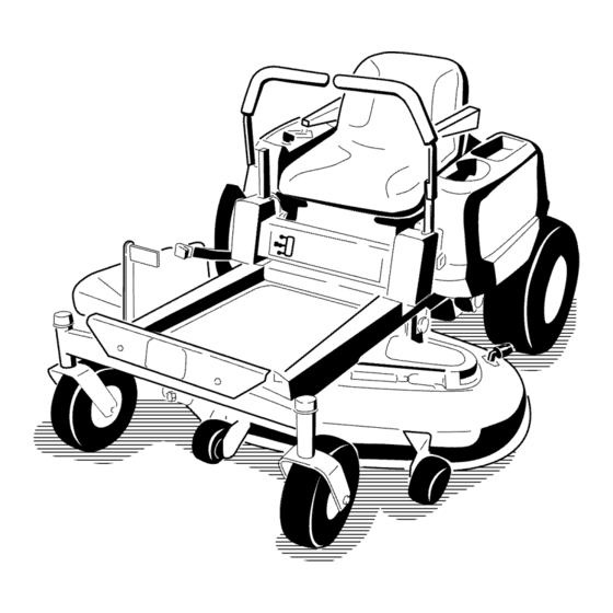
Product Overview Figure 3 1. Footrest 4. Control panel 7. Rear drive wheel 10. Anti-scalp roller 5. Motion control levers 11. Front caster wheel 2. Height of cut lever 8. Washout fitting 3. Fuel gauge 6. Operator seat 9. Mower deck Figure 4 1. -
Page 12: Controls
Controls reverse; wheel speed is proportional to the amount the lever is moved. Move the control levers outward from Become familiar with all of the controls in Figure 3, the center to the park position and exit the machine Figure 4, and Figure 5 before you start the engine and (Figure 15). -
Page 13: Operation
Operation Note: Determine the left and right sides of the machine from the normal operating position. Think Safety First Please carefully read all of the safety instructions and decals in the safety section. Knowing this information could help you, your family, pets or bystanders avoid injury. - Page 14 In certain conditions, gasoline is extremely In certain conditions during fueling, static flammable and highly explosive. A fire or electricity can be released causing a spark explosion from gasoline can burn you and which can ignite the gasoline vapors. A fire others and can damage property.
-
Page 15: Checking The Engine Oil Level
Add the correct amount of gas stabilizer/conditioner tank (Figure 9). This space in the neck of the tank to the gas. allows gasoline to expand. Do not fill the fuel tank completely full. Note: A fuel stabilizer/conditioner is most effective 4. -
Page 16: Operating The Blades
between attempts. Failure to follow these instructions can damage the starter motor. G005056 Figure 10 1. Control panel 2. Blade control switch—Off position G005058 3. Move the throttle lever to Choke before starting a cold engine (Figure 11). Figure 12 1. -
Page 17: Stopping The Engine
The Safety Interlock System If safety interlock switches are disconnected or damaged the machine could operate unexpectedly causing personal injury. • Do not tamper with the interlock switches. G005059 • Check the operation of the interlock switches daily and replace any damaged switches before operating the machine. -
Page 18: Driving Forward Or Backward
Driving Forward or Backward The throttle control regulates the engine speed as measured in rpm (revolutions per minute). Place the throttle control in the Fast position for best performance. Always operate in the full throttle position. The machine can spin very rapidly. The operator may lose control of the machine and cause personal injury or damage to the machine. -
Page 19: Stopping The Machine
Adjusting the Height of Cut To turn, release the pressure on the motion control lever toward the direction you want to turn. To stop, push the motion control levers to neutral. Using the Height of Cut Lever To adjust the height of cut, pull inward and up on the Stopping the Machine lever and move it to the desired position. -
Page 20: Positioning The Seat
Using the Foot Assist Pedal (Model Positioning the Seat 74375 only) The seat can move forward and backward. Position the The foot assist pedal can be used with the height of cut seat where you have the best control of the machine lever to help adjust the deck height. -
Page 21: Pushing The Machine By Hand
4. Move the bypass levers rearward and then down to lock them in place as shown in Figure 22 to disengage the wheel motors. Repeat this on each side of the machine. 5. Move the motion control levers inward to the neutral position. -
Page 22: Operating Tips
Mowing Direction Alternate mowing direction to keep the grass standing Without the grass deflector, discharge cover, straight. This also helps disperse clippings which or complete grass catcher assembly mounted enhances decomposition and fertilization. in place, you and others are exposed to blade contact and thrown debris. - Page 23 File down any nicks and sharpen the blades as necessary. If a blade is damaged or worn, replace it immediately with a genuine Toro replacement blade.
-
Page 24: Maintenance
Maintenance Note: Determine the left and right sides of the machine from the normal operating position. Recommended Maintenance Schedule(s) Maintenance Service Maintenance Procedure Interval • Check the safety interlock system. • Check the air cleaner for dirty, loose or damaged parts. •... -
Page 25: Premaintenance Procedures
Premaintenance Lubrication Procedures Greasing the Bearings Raising the Seat Service Interval: Every 25 hours—Grease all lubrication points. Make sure the motion control levers are locked in the Grease Type: No. 2 General Purpose Lithium Base park position. Lift the seat forward. Grease The following components can be accessed by raising 1. -
Page 26: Engine Maintenance
Engine Maintenance 4. Connect a grease gun to each fitting (Figure 24 and Figure 25). Pump grease into the fittings until grease begins to ooze out of the bearings. Servicing the Air Cleaner 5. Wipe up any excess grease. Service Interval: Before each use or daily—Check the air cleaner for dirty, loose or damaged parts. -
Page 27: Servicing The Engine Oil
Servicing Paper Element Checking the Oil Level Service Interval: Every 50 hours—Service the paper Service Interval: Before each use or daily—Check the element. (more often under extremely engine oil level. dusty, dirty conditions) 1. Park the machine on a level surface, disengage the Every 100 hours—Replace the paper blade control switch, stop the engine, and remove element. - Page 28 low, add oil of the proper type up to the full mark. Reinstall oil fill cap/dipstick and screw tight. Changing the Oil and the Filter Service Interval: Every 100 hours—Change the engine oil and filter. Refill with service class SG, SH, SJ or higher oil as specified in the “Viscosity Grades”...
-
Page 29: Servicing The Spark Plug
12. Install the replacement oil filter to the adapter. Turn the oil filter clockwise until the rubber gasket contacts the pad, then tighten the filter an additional 3/4 to 1 turn (Figure 30). Wipe up any excess oil on the frame. 13. -
Page 30: Cleaning The Blower Housing
Cleaning the Blower Housing Fuel System Maintenance To ensure proper cooling, make sure the grass screen, cooling fins, and other external surfaces of the engine are kept clean at all times. Annually or every 100 hours of operation (more often under extremely dusty, dirty conditions), remove the In certain conditions, gasoline is extremely flammable and highly explosive. -
Page 31: Electrical System Maintenance
Electrical System Maintenance Charging the Battery Warning CALIFORNIA Proposition 65 Warning Battery posts, terminals, and related accessories contain lead and lead compounds, G005071 chemicals known to the State of California to cause cancer and reproductive harm. Wash hands after handling. Figure 33 1. -
Page 32: Servicing The Fuses
Incorrect battery cable routing could damage the machine and cables causing sparks. Sparks can cause the battery gasses to explode, resulting in personal injury. • Always disconnect the negative (black) battery cable before disconnecting the positive (red) cable. Figure 35 •... -
Page 33: Drive System Maintenance
Drive System Maintenance Checking the Tire Pressure Service Interval: Every 25 hours—Check tire pressure. Maintain the air pressure in the front and rear tires as G005073 specified. Uneven tire pressure can cause uneven cut. Check the pressure at the valve stem (Figure 37). Check the tires when they are cold to get the most accurate pressure reading. -
Page 34: Mower Maintenance
4. Damage wear or damage. File down any nicks and sharpen the blades as necessary. If a blade is damaged or worn, replace it immediately with a genuine Toro replacement Checking for Bent Blades blade. For convenient sharpening and replacement, you may want to keep extra blades on hand. -
Page 35: Removing The Blades
The blades must be replaced if a solid object is hit, if the blade is out of balance, or the blade is bent. To ensure optimum performance and continued safety conformance of the machine, use genuine Toro replacement blades. Replacement blades made by other manufacturers may result in non-conformance with safety standards. -
Page 36: Leveling The Mower Deck
Leveling the Mower Deck Check to ensure the mower deck is level any time you install the mower or when you see an uneven cut on your lawn. The mower deck must be checked for bent blades prior to leveling; any bent blades must be removed and replaced. -
Page 37: Adjusting The Front-To-Rear Blade Slope
G005278 Figure 47 Mower Decks with 3 Blades 1. Blades side to side 3. Outside cutting edges 2. Sail area of blade 4. Measure from the tip of the blade to the flat surface here G005074 5. Measure between the outside cutting edges and the flat surface (Figure 46 and Figure 47). -
Page 38: Removing The Mower
G009658 Figure 49 Mower Decks with 2 Blades 1. Blades front to rear 2. Measure from the tip of the blade to the flat surface here Figure 51 1. Adjusting rod 3. Lock nut 2. Adjusting block 7. To raise the front of the mower, tighten the adjustment nut. -
Page 39: Mower Belt Maintenance
Mower Belt Maintenance Inspecting the Belts Service Interval: Every 25 hours—Check the belts for wear/cracks. Check the belts for cracks, frayed edges, burn marks, or any other damage. Replace damaged belts. Replacing the Mower Belt Squealing when the belt is rotating, blades slipping when cutting grass, frayed belt edges, burn marks, and cracks are signs of a worn mower belt. -
Page 40: Installing The Mower
6. Route the new belt around the engine pulley and mower pulleys (Figure 54). 7. Pull the idler pulley in the direction shown in Figure 54 and route the belt onto the idler pulley (Figure 54). 8. Install the belt covers over the outside spindles. Installing the Mower 1. -
Page 41: Cleaning
Cleaning Note: If the mower is not clean after one washing, soak it and let it stand for 30 minutes. Then repeat the process. Washing the Underside of the 8. Run the mower again for one to three minutes to Mower remove excess water. -
Page 42: Storage
Storage Important: Do not store stabilizer/conditioned gasoline over 30 days. Cleaning and Storage 11. Remove the spark plug(s) and check its condition; refer to Servicing the Spark Plug in the Engine 1. Disengage the blade control switch, move the Maintenance section. With the spark plug(s) motion controls outward to the park position, stop removed from the engine, pour two tablespoons of the engine, and remove the key. -
Page 43: Troubleshooting
Troubleshooting Problem Possible Cause Corrective Action The engine overheats. 1. The engine load is excessive. 1. Reduce ground speed. 2. The oil level in the crankcase is low. 2. Add oil to the crankcase. 3. The cooling fins and air passages 3. - Page 44 Problem Possible Cause Corrective Action There is abnormal vibration. 1. The engine mounting bolts are loose. 1. Tighten the engine mounting bolts. 2. The engine pulley, idler pulley, or blade 2. Tighten the appropriate pulley. pulley is loose. 3. The engine pulley is damaged. 3.
-
Page 45: Schematics
Schematics G009744 Electrical Diagram (Rev. A) - Page 46 Notes:...
- Page 47 Notes:...
-
Page 48: The Toro Total Coverage Guarantee
Countries Other than the United States or Canada Customers who have purchased Toro products exported from the United States or Canada should contact their Toro Distributor (Dealer) to obtain guarantee policies for your country, province, or state. If for any reason you are dissatisfied with your Distributor’s service or have difficulty obtaining guarantee information, contact the Toro importer.
Need help?
Do you have a question about the TimeCutter Z5030 and is the answer not in the manual?
Questions and answers