
Related Manuals for Toro 74262TE


Summary of Contents for Toro 74262TE
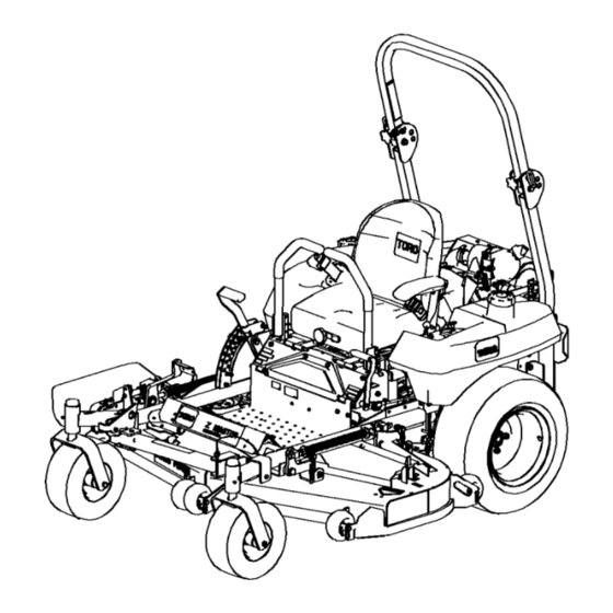
- Page 1 Form No. 3355-163 Rev A Z500 Z Master, With 152cm Turbo Force® Side Discharge Mower Model No. 74262TE—Serial No. 260000001 and Up Register your product at www.Toro.com Original Instructions (EN)
-
Page 2: Table Of Contents
Whenever you need service, genuine Toro parts, Safety ..............4 or additional information, contact an Authorized Safe Operating Practices ...... 4 Service Dealer or Toro Customer Service and have Toro Riding Mower Safety ....5 the model and serial numbers of your product Sound Pressure........6 ready. - Page 3 Loading Machines ......27 Leveling the Mower at Three Using the Z Stand® ......28 Positions ......50 Operating Tips ........29 Servicing the Cutting Blades....52 Maintenance............31 Replacing the Grass Deflector.... 54 Recommended Maintenance Cleaning ............ 55 Schedule(s) ....... 31 Cleaning Under the Mower ....
-
Page 4: Safety
Safety ◊ the type of machine is unsuitable for its task; ◊ lack of awareness of the effect of This machine meets or exceeds European Standards in effect at the time of production. ground conditions, especially slopes; However, improper use or maintenance by the ◊... -
Page 5: Toro Riding Mower Safety
• Disengage drive to attachments, stop the engine, and disconnect the spark plug wire(s) Toro Riding Mower Safety or remove the ignition key – before clearing blockages or unclogging The following list contains safety information chute; specific to Toro products or other safety... -
Page 6: Sound Pressure
• Battery gases can explode. Keep cigarettes, Sound Pressure sparks and flames away from battery. • Use only genuine Toro replacement parts to This unit has a maximum sound pressure level ensure that original standards are maintained. at the operator’s ear of 90 dBA, based on •... -
Page 7: Slope Chart
Slope Chart... -
Page 8: Safety And Instructional Decals
Safety and Instructional Decals Safety decals and instructions are easily visible to the operator and are located near any area of potential danger. Replace any decal that is damaged or lost. 1-643339 93-7824 1. Thrown object hazard—stay a safe distance from the machine. - Page 9 107-2131 1. Hydraulic oil level 2. Warning—do not touch the hot surface. 99-8939 1. Read the Operator’s 3. Remove the ignition key Manual. and read the instructions before servicing or performing maintenance. 2. Height of cut 105-7797 107-3069 1. Warning—there is no rollover protection when the roll bar is down.
- Page 10 107-3962 1. Height of cut in millimeters 107-3961 1. Height of cut in millimeters 107-3963 1. Cutting/dismemberment 2. Cutting/dismemberment 3. Thrown object hazard—keep 4. Before starting the engine, hazard, mower blade—do hazard of hand or foot, bystanders a safe distance clean grass and debris from not carry passengers and mower blade—remove the...
- Page 11 107-3964 1. Warning—do not use drugs or alcohol. 3. Warning—engage the parking brake, 5. Read the Operator’s Manual. stop the engine, and remove the ignition key before leaving the machine. 2. Warning—read the Operator’s Manual 4. Warning—wear hearing protection. and receive training. 107-3978 1.
- Page 12 107-3996 1. Engine 2. Cutting blade 107-3984 Battery Symbols 1. Read the instructions before 4. Grease Some or all of these symbols are on your battery servicing or performing maintenance. 2. Hourly interval 5. Tire pressure 1. Explosion hazard 6. Keep bystanders a safe 3.
- Page 13 110-5721 1. Engine—stop 5. Fast 2. Engine—run 6. Continuous variable setting 3. Engine—start 7. Slow 4. Power take-off (PTO) 8. Choke 107-8077 1. Fast 3. Neutral 5. Warning-read— the 7. Explosion hazard—no re, Operator’s Manual. open ames, or smoking; avoid sparks. 2.
-
Page 14: Product Overview
Product Overview Controls Become familiar with all the controls before you start the engine and operate the machine (Figure 3 and Figure 4). Figure 4 1. Ignition switch 4. Power take off (PTO) Figure 3 2. Throttle 5. Hour meter 3. -
Page 15: Operation
Operation In certain conditions during fueling, static Note: Determine the left and right sides of the electricity can be released causing a spark machine from the normal operating position. which can ignite the gasoline vapors. A fire or explosion from gasoline can burn you and Adding Fuel others and can damage property. -
Page 16: Checking The Engine Oil Level
• Cleans the engine while it runs • Eliminates gum-like varnish buildup in the fuel There is no rollover protection when the roll system, which causes hard starting bar is in the down position. Important: Do not use fuel additives •... -
Page 17: Think Safety First
Think Safety First 5. To raise the roll bar, remove the hairpin cotter pins and remove the two pins (Figure 6). Please read all safety instructions and symbols 6. Raise the roll bar to the upright position and in the safety section. Knowing this information install the two pins and secure them with the could help you or bystanders avoid injury. -
Page 18: Operating The Parking Brake
Setting the Parking Brake 1. Move the motion control levers (Figure 16) out to the neutral lock position. 2. Pull up and back on the parking brake lever to set the parking brake (Figure 10). The parking brake lever should stay firmly in the engaged position. - Page 19 3. Move the PTO (power take off) switch to the Off position (Figure 11). Figure 13 Figure 11 1. Throttle—fast 2. Throttle—slow 1. PTO—on 2. PTO—off 6. Turn the ignition key to Start (Figure 14). 4. Move the choke control to the on position When the engines starts, release the key.
-
Page 20: Operating The Power Take Off
4. Turn the ignition key to the off position and remove the key (Figure 14). 5. Close the fuel shut off valve before transporting or storing the machine. Refer to Fuel System Maintenance, page 36. Important: Make sure that the fuel shut off valve is closed before transporting or storing the machine, as fuel leakage may occur. -
Page 21: Driving Forward Or Backward
engaged or if you rise from the seat when the PTO is engaged. Machine can spin very rapidly. Operator Testing the Safety Interlock System may lose control of machine and cause personal injury or damage to machine. Test the safety interlock system before you use •... -
Page 22: Stopping The Machine
Driving Backward 1. Move the levers to the center, un-locked position. 2. To go backward, slowly pull the motion control levers rearward (Figure 16). To go straight, apply equal pressure to both motion control levers (Figure 16). To turn, release pressure on the motion control lever toward the direction you want to turn (Figure 16). -
Page 23: Adjusting The Flow Baffle
5. Install the flange nut bushing, spacer, and bolt. Torque to 40-45 ft-lb (54-61 N•m) (Figure 18 , Figure 19 and Figure 20 ). 6. Repeat this adjustment on the other anti-scalp rollers. Figure 20 1. Anti-scalp roller 4. Flange Nut 2. -
Page 24: Positioning The Flow Baffle
• This position is similar to the benefits of the • Use for short, light grass mowing conditions. Toro SFS mower. • Use in dry conditions. • For smaller grass clippings. • Propels grass clippings farther away from the mower. -
Page 25: Using The Lift Assist Lever
Using the Lift Assist Lever The lift assist lever is used along with the height-of-cut lever for raising the mower. This allows for easier raising of the mower. 1. Place your foot onto lift assist lever. 2. Press on the lift assist lever while pulling up on the height-of-cut lever (Figure 25). -
Page 26: Using The Side Discharge
Without the grass deflector, discharge cover, or complete grass catcher assembly mounted in place, you and others are exposed to blade contact and thrown debris. Contact with rotating mower blade(s) and thrown debris will cause injury or death. • Never remove the grass deflector from the mower because the grass deflector routes material down toward the turf. -
Page 27: Loading Machines
Important: Do not use the motion control levers as anchors for tieing the machine down. Loading a unit onto a trailer or truck increases the possibility of backward • Secure a trailer to the towing vehicle with tip-over and could cause serious injury or safety chains. -
Page 28: Using The Z Stand
Using the Z Stand® The Z Stand raises the front end of the machine to allow you to clean the mower and remove the blades. The machine could fall onto someone and cause serious injury or death. Figure 31 1. Z Stand (Positioned in slot) 3. Latch resting on pivot tab •... -
Page 29: Operating Tips
Mowing Direction Alternate mowing direction to keep the grass standing straight. This also helps disperse clippings which enhances decomposition and fertilization. Mow at Correct Intervals Normally, mow every four days. But remember, grass grows at different rates at different times. So to maintain the same cutting height, which is a good practice, mow more often in early spring. - Page 30 Check the cutter blades daily for sharpness, and for any wear or damage. File down any nicks and sharpen the blades as necessary. If a blade is damaged or worn, replace it immediately with a genuine TORO replacement blade.
-
Page 31: Maintenance
Maintenance Recommended Maintenance Schedule(s) Maintenance Service Maintenance Procedure Interval After the rst 8 operating • Check the hydraulic uid level. hours After the rst 25 • Change the hydraulic lter and oil. operating hours • Check the safety interlock system. •... - Page 32 How to Grease 1. Disengage the PTO, move the motion control levers to the neutral locked position and set the parking brake. 2. Stop the engine, remove the key, and wait for all moving parts to stop before leaving the operating position.
-
Page 33: Engine Maintenance
Figure 35 1. Air cleaner body 4. Air cleaner cover 2. Primary lter 5. Safety lter 3. Latch Figure 34 4. Clean the inside of the air cleaner cover with compressed air. 4. Grease the idler pulley pivot (Fig. 38). 5. -
Page 34: Servicing The Engine Oil
Installing the Filters 2. Disengage the PTO, turn the ignition key to off, and remove the key. Important: To prevent engine damage, 3. Wait for all moving parts to stop before leaving always operate the engine with both air filters the operating position and then chock or block and cover installed. -
Page 35: Servicing The Spark Plugs
6. When oil has drained completely, close the drain valve. Note: Dispose of the used oil at a recycling center. Figure 39 1. Oil lter 3. Adapter 2. Adapter gasket 3. Pour new oil in through the center hole of the filter. -
Page 36: Fuel System Maintenance
Checking the Spark Plugs 1. Look at the center of the spark plugs (Figure 40). If you see light brown or gray on the insulator, the engine is operating properly. A black coating on the insulator usually means that the air cleaner is dirty. Figure 41 1. -
Page 37: Servicing The Fuel Tank
4. Loosen the hose clamp at the fuel filter and slide it up the fuel line away from the fuel filter (Figure 42). 5. Disconnect the fuel line from the fuel filter (Figure 42). 6. Open the fuel shutoff valve. Note: Allow gasoline to drain into a fuel container can or drain pan (Figure 42). - Page 38 6. Remove both wing nuts (1/4 inch) securing the battery clamp (Figure 43). Incorrect battery cable routing could 7. Remove the battery. damage the machine and cables causing sparks. Sparks can cause the battery gasses Installing the Battery to explode, resulting in personal injury. 1.
-
Page 39: Servicing The Fuses
Drive System Maintenance Adjusting the Tracking Note: Determine the left and right sides of the machine from the normal operating position. The right hand pump has a knob for adjusting the tracking. Important: Adjust the handle neutral and hydraulic pump neutral before adjusting the tracking. -
Page 40: Checking The Tire Pressure
1. Disengage the PTO, move the motion control levers to the neutral locked position and set the parking brake. 2. Stop the engine, remove the key, and wait for all moving parts to stop before leaving the operating position. 3. Remove the cotter pin. 4. -
Page 41: Cooling System Maintenance
Figure 50 1. Engine screen 2. Oil cooler Cleaning the Engine Fins Every 100 hours clean the engine cylinder and cylinder head cooling fins. Also clean around carburetor, governor levers and linkage. This will make sure adequate cooling to hydraulic pumps, motors and engine and will reduce the possibility Figure 49 of overheating and mechanical damage. -
Page 42: Belt Maintenance
and cracks are signs of a worn mower belt. Replace the mower belt if any of these conditions are evident. 1. Disengage the PTO, move the motion control levers to the neutral locked position, and set the parking brake. 2. Stop the engine, remove the key, and wait for all moving parts to stop before leaving the operating position. -
Page 43: Adjusting The Mower Belt
Figure 54 1. Belt cover 3. Insert slot into the tab 2. Latch 4. Bolt Figure 53 Adjusting the Mower Belt 1. Clutch 4. Belt guide 7. Belt guide 10. Rear left Tension installed side pulley 2. Mower 5. Mower 8. -
Page 44: Replacing The Pump Drive
Figure 55 1. Center bolt 3. Left support plate 2. Alignment hole 4. Spring loaded idler Figure 57 1. Spring loaded idler pulley 4. Idler pulley arm 5. If adjustment is required, loosen the mower 2. Top alignment hole 5. Belt 3. -
Page 45: Controls System Maintenance
pulleys (Figure 59). Remove belt between pulleys. Figure 59 Figure 60 1. Neutral locked position 3. Neutral potion 2. Control lever 2. Install new belt around engine and hydro pump pulleys (Figure 59). 6. Pull the lever back until the clevis pin (on arm 3. -
Page 46: Hydraulic System Maintenance
2. Clean the area around filler neck of hydraulic tank (Figure 62). Figure 62 1. Cap 3. Cold uid level-full 2. Bafe 4. Hot uid level-full 3. Remove the cap from the filler neck. Look Figure 61 inside to check if there is fluid in the reservoir (Figure 62). -
Page 47: Replacing The Hydraulic Filter And Oil
Hydraulic fluid escaping under pressure can penetrate skin and cause injury. • If hydraulic fluid is injected into the skin it must be surgically removed within a few hours by a doctor familiar with this type of injury. Gangrene Figure 63 may result if this is not done. -
Page 48: Bleeding The Hydraulic System
Bleeding the Hydraulic System Hydraulic fluid escaping under pressure can The traction system is self bleeding, however, it penetrate skin and cause injury. may be necessary to bleed the system if fluid is • If hydraulic fluid is injected into the skin changed or after work is performed on the system. - Page 49 This adjustment must be made with drive wheels 3. Move the motion control lever forward and turning. reverse, then back to neutral. The wheel must stop turning or slightly creep in reverse. 1. Raise the frame and use jack stands to hold up the machine so drive wheels can rotate freely.
-
Page 50: Positions
4. Move the motion control lever forward and 5. Lower the mower to the 3 inch (76 mm) reverse, then back to neutral. The wheel must height-of-cut position. stop turning or slightly creep in reverse. 6. Inspect the four chains. The chains need to 5. - Page 51 7. If the measurements at positions B or C are not correct, loosen the bolt attaching the rear chain to the rear support arm (Figure 68). Figure 69 1. Measure here from blade 2. Measure at A and B to hard surface Figure 68 1.
-
Page 52: Servicing The Cutting Blades
If a blade is (Figure 71). damaged or worn, replace it immediately with a genuine Toro replacement blade. For convenient If you notice any damage, wear, or a slot sharpening and replacement, you may want to forming in this area (Figure 71), immediately keep extra blades on hand. - Page 53 1. Rotate the blades until the ends face forward Toro replacement blades. Replacement blades and backward (Figure 72). Measure from a made by other manufacturers may result in level surface to the cutting edge, position A, of non-conformance with safety standards.
-
Page 54: Replacing The Grass Deflector
Replacing the Grass Deector Figure 74 An uncovered discharge opening could 1. Blade 2. Balancer allow the lawn mower to throw objects in the operator’s or bystander’s direction and result in serious injury. Also, contact with Installing the Blades the blade could occur. 1. -
Page 55: Cleaning Under The Mower
Figure 76 1. Bolt 5. Spring installed 2. Spacer 6. Grass Deector 7. L end of spring, place 3. Locknut behind deck edge before installing bolt 8. J hook end of spring 4. Spring Cleaning Cleaning Under the Mower Remove the grass buildup under the mower daily. 1. -
Page 56: Storage
Storage stabilizer manufacture. Do not use an alcohol based stabilizer (ethanol or methanol). 1. Disengage the power take off (PTO), set the Note: A fuel stabilizer/conditioner is parking brake and turn the ignition key to off. Remove spark plug wire. Remove the key. most effective when mixed with fresh gasoline and used at all times. -
Page 57: Troubleshooting
Troubleshooting Problem Possible Cause Corrective Action Starter does not crank 1. Blade control (PTO) is 1. Move blade contro (PTO) engaged. to disengaged. 2. Parking brake is not on. 2. Set the parking brake. 3. Operator is not seated. 3. Sit on the seat. 4. - Page 58 Problem Possible Cause Corrective Action Machine does not drive. 1. By pass valve is not 1. Tighten the by pass closed tight. valve. 2. Drive or pump belt is 2. Change the belt. worn, loose or broken. 3. Drive or pump belt is off 3.
- Page 59 Problem Possible Cause Corrective Action Blades do not rotate. 1. Drive belt is worn, loose 1. Check the belt tension. or broken. 2. Drive belt is off pulley. 2. Install drive belt and check adjusting shafts and belt guides for correct position.
-
Page 60: Schematics
Schematics Wire Diagram (Rev. A)