
Related Manuals for Uni-Mig PRO-CRAFT240 MIG


Summary of Contents for Uni-Mig PRO-CRAFT240 MIG
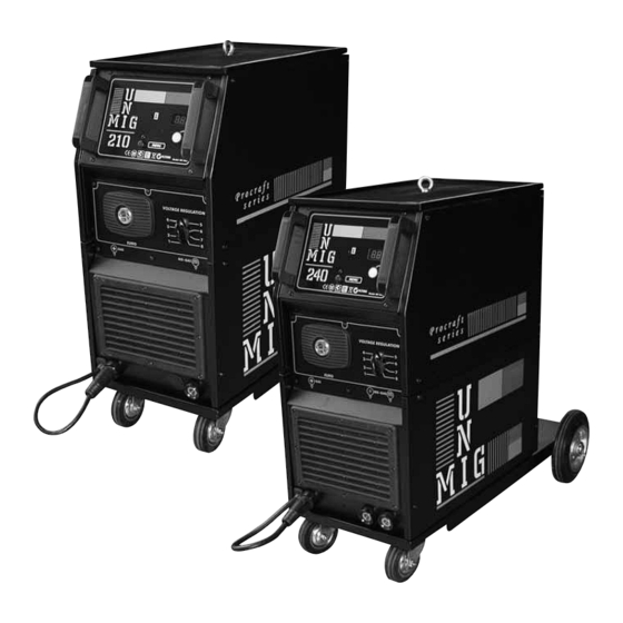
- Page 1 UNI FLAME AUTOLIFT PRO-CRAFT SERIES 210/240 MIG Manual 240 Volt Standard MIG / MAG...
- Page 2 YEARS Warranty Machine Model Description Part Number MIG Inverter KPC210 / 240 CONTENTS PAGE No: Safety Main Parameter. Machine Features Installation & Operation Caution Maintenance Troubleshooting Machine Model This welding equipment for industrial and professional use conforms to IEC 60974 International Safety Standard. We hereby state that we provide three year of guarantee for this welding Power Source from the date of purchase.
- Page 3 SAFETY Welding and cutting equipment can be dangerous to both the operator and people in or near the surrounding working area, if the equipment is not correctly operated. Equipment must only be used under the strict and comprehensive observance of all relevant safety regulations. Please read and understand this instruction manual carefully before the installation and use/operation of this equipment.
-
Page 4: Specifications
PART NUMBER KPC210 KPC240 PRIMARY INPUT VOLTAGE 240V 1 Phase 240V 1 Phase Ieff 16Amps 20Amps WELDING CURRENT 30-210 Amps 30-240 Amps VOLTAGE STEPS DUTY CYCLE 40°C 18% @ 210 Amps 24.5V 15% @ 240 Amps 26V 60% @ 110 Amps 19.5V 60% @ 150 Amps 21.5V 100% @ 95 Amps 18.75V 100% @ 120 Amps 20V... - Page 5 2.4 GAS BOTTLE INSTALLATION Put the gas bottle in vertical position on the gas bottle holder plane and position the bottle so that it is lays on the gas bottle holder and fix it with the chain and the spring clip, like in pic E. Tightly connect the gas hose, which comes from the back of the machine to the brass nipple of supplied regulator adjust argon regulator to deliver the required litres per minute.
-
Page 6: Welding
Mod.A Mod.B LEGENDA: LEGENDA: LED 1 = Thermal protection LED = Thermal protection LED 2 = Trigger normal – Manual welding LED 3 = Trigger latch – Automatic welding LED 4 = Stich welding LED 5 = Spot welding S1 = Menù. To select welding parameter on the display S1 = Menù. - Page 7 Wire speed: It is possible to regulate the wire speed using the knobs of the encoder Pregas: It is possible to regulate the gas open time using the knob of the encoder before the arc prime Ramp up: It is possible to regulate the wire increasing gradually using the knobs of the encoder in order to have the one selected at point 4.2.1 Burn back: it is possible to regulate, using the knob of the encoder, the wire length came out at the end of welding process.
-
Page 8: Welding Tips
WELDING GUIDE GENERAL RULE GENE G G EN N E ENER When welding on the lowest output settings, it is necessary to keep the arc as short as possible. This should be achieved by holding welding torch as close as possible and at an angle of approximately 60 degrees to the workpiece. -
Page 9: Description Of Graphics
DESCRIPTION OF GRAPHICS... - Page 12 CAUTION 1. Working Environment. The environment in which this welding equipment is installed must be free of grinding dust, corrosive chemicals, flammable gas or materials etc, and at no more than maximum of 80% humidity. When using the machine outdoors protect the machine from direct sun light, rain water and snow etc;...
-
Page 13: Troubleshooting
MAINTENANCE WARNING: Exposure to extremely dusty, damp, or corrosive air is damaging to the welding machine. In order to prevent any possible failure or fault of this welding equipment, clean the dust at regular intervals with clean and dry compressed air of required pressure.
Need help?
Do you have a question about the PRO-CRAFT240 MIG and is the answer not in the manual?
Questions and answers