Table of Contents
Advertisement
Quick Links
Advertisement
Table of Contents

Related Manuals for Xinje DS3 series servo


Summary of Contents for Xinje DS3 series servo
- Page 1 User manual Xinje Electronic Co., Ltd. No. SC309 20090706 1.0...
-
Page 3: Safety Notes
Please check if there is broken because of transportation Is the screw loose? Check the screw with screw driver Check the motor code on servo drive and motor, if Motor code they are the same If there is inconsistent item, please contact XINJE sales department. - Page 4 DS3 series servo manual 2. Type Servo drive DS3 – 2 1P8 Suitable motor capacity 0P7: 0.75KW, 1P5: 1.5KW, 1P8: 1.8KW, 2P7: 2.7KW Voltage level: 2: 220V, 4: 380V Servo series name: DS3: standard type Servo motor MS -110 ST - M 06030 A Z- 2 1P8...
-
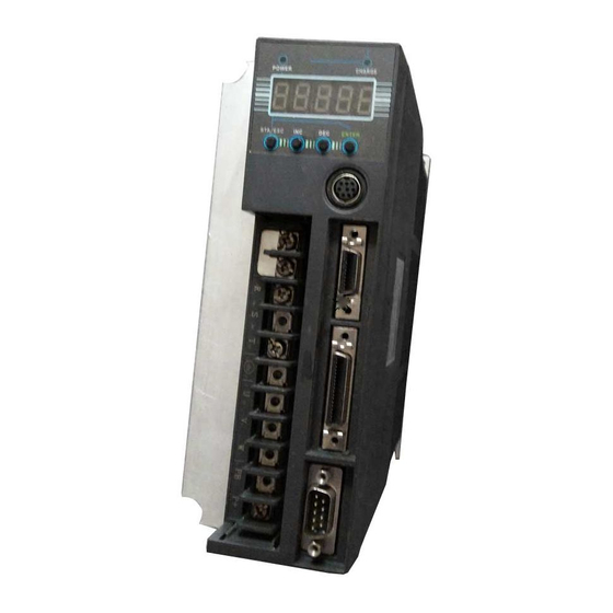
Page 5: Part Name
DS3 series servo manual 3. Part name Servo motor Servo drive Power LED: turn on when servo drive is power on. Charge LED: turn on when servo drive is power on. After power off, it will be on until there is no charge in the capacitance of servo drive. - Page 6 DS3 series servo manual CN2: connect the encoder. CN1: command input, sequence I/O signal Power and servo motor terminals: to connect the power supply and power cable of servo motor. COM2: connect with PLC, HMI, ect. ►► Installation 1. Servo motor MS series servo motor can be installed vertical or horizontal.
- Page 7 Do not make large tension for the cable especially for the 0.2mm , 0.3mm cables. 2. Servo drive DS3 series servo drive is base-type. Please install it correctly otherwise there will be error. 1) Storage temperature Store the servo drive in the range of -20~+85 ℃. 2) Installation location...
- Page 8 DS3 series servo manual close to the Install the shockproof device on the installation side of servo drive vibration close to the To prevent the corrosive gas from the servo drive, otherwise there will corrosive gas be error for the circuit.
- Page 9 DS3 series servo manual Direction of servo drive The front side must face to the operator, and be vertical to the wall. Ambient in the control cabinet: Temperature: 0~50 ℃ Humidity: below 90% RH Vibration: 4.9m/s ...
- Page 10 DS3 series servo manual (2) MS-110ST-M06030□□-21P8 installation dimension Unit: mm Type MS-110ST-M06030□□-21P8 (3) MS-130ST-M10015□□-21P5 installation dimension Unit: mm Type MS-130ST-M10015□□-21P5...
- Page 11 DS3 series servo manual 2. Servo drive Unit: mm ►► Wiring Main circuit terminals Terminal Function Explanation connect 1 and 2 are shorted together. Connect reactor reactor between 1 and 2 to suppress high harmonics R, S, T Power supply input...
- Page 12 DS3 series servo manual 2. Servo motor winding connector terminals Signal Motor terminal 80 series 110, 130 series 3. CN1 terminal arrangement Look at the solder side: Terminal Explanation Terminal Explanation phase V-REF Analog set, speed transistor output SO3- Output terminal...
- Page 13 DS3 series servo manual Vacant B phase differential output Input terminal 3 Input terminal 2 A phase differential output Input terminal 1 Ground Ground 4. I/O signal (1) Input signal Type Input terminal Function Digital input SI1~SI7 Multi-functional input Pulse input PULS+, PULS- P2-00=1: A phase pulse;...
- Page 14 DS3 series servo manual Drive Motor encoder port Name Drive Motor encoder port Name port port 110/130 110/130 series series series series Cover SHIELD 6. Communication port (1) COM1 COM1 support RS232 mode, connect with PC to debug the servo. When communicate with PC, set F5-00 to C-OUT mode, the panel operation is invalid.
- Page 15 DS3 series servo manual (2) COM2 COM2 supports RS232 and RS485, Modbus-RTU protocol. It can realize 1:N communication. It is used to connect with HMI, PLC and other devices. Its parameters can be configured. Look at the servo drive side, COM2 pin figure:...
- Page 16 DS3 series servo manual Modbus station No. can be set in P0-03. Parameter Function Unit Default value Set range - P0-03 Modbus station No. 1~255 7. Connection example...
- Page 17 DS3 series servo manual AC 220V (50/60Hz) Properly handle the shield thread Speed command V-REF Speed limit 10 Ω ±10 Rated speed T-REF Torque command 10 Ω Torque limit ±10 Rated torque Encoder 10 Ω Output PULS+ PULS PULS- SIGN+...
-
Page 18: Operation Panel
DS3 series servo manual ►► Operation panel 1. Basic operation Set the parameters by operation panel. 5-bit LED displays the servo state, parameters, alarm code. Button Function STATUS/ESC Switch the state and return Increase or decrease the data, group number... - Page 19 DS3 series servo manual parameter number in this group Alarm state E-XXX: XXX means alarm code 2. Running state Display the servo state with LED bit and code in state display mode. Select the display state Power on and enter the state display. If you cannot see the state display, press STATUS/ESC button.
- Page 20 DS3 series servo manual Code content Code Content Sleep mode Servo OFF state (motor is not power on) Running Servo enable state (motor is power on) Forward suppression state P-OT OFF state. Refer to chapter 4-2-2 Reverse suppression state N-OT OFF state. Refer to chapter 4-2-2...
- Page 21 DS3 series servo manual Code content Code Content Sleep mode Servo OFF state. (motor is power off) Running Servo enable state. (motor is power on) Forward suppression state P-OT OFF state Reverse suppression state N-OT OFF state 3. Monitoring state It is capable to monitor the input command, I/O signal and internal state of servo drive by monitoring state.
- Page 22 DS3 series servo manual U-004 Rotation angle (electricity angle) 0.1° U-005 Bus voltage U-006 Module temperature 0.1 ℃ U-007 Input command pulse speed (0000~FFFF)*1 U-008 Shift command Command (0000~FFFF)*9999 pulse value pulse U-009 (0000~FFFF)*1 U-010 Rotation angle Encoder (0000~FFFF)*9999 (encoder value)
- Page 23 DS3 series servo manual Input signal state Segment Explanation Modbus Segment Explanation Modbus Code address Code address LED4_0 /SPD-A internal 0x0808 LED5_0 /S-ON servo signal 0x0800 speed setting LED4_1 /SPD-B internal 0x0809 LED5_1 /P-CON proportional 0x0801 speed setting action command...
- Page 24 DS3 series servo manual checking (/VLT) LED2_6 Brake lock (/BK) 0x0818 LED2_7 Warn (/WARN) 0x0819 Note: the state value read from communication: 0=OFF, 1=ON. U-022 can display the I/O terminal state. Next we will explain them. Figure 1 Figure 2 In figure 1, input terminal state will show in LED5, output terminal state will show in LED2.
- Page 25 DS3 series servo manual View the system information Press STATUS/ESC to switch to auxiliary function state, set the group number to 0. Press INC or DEC to select the code. Press ENTER to enter, press STATUS/ESC to return. System information code:...
- Page 26 DS3 series servo manual Enable Reverse jog (2) Test run (F1-01) Make sure the motor is not connected to the machine before test run. When servo drive connects to non-original encoder or power cables, please enter test run state to ensure the encoder or power cables connect correctly.
- Page 27 DS3 series servo manual (3) Press ENTER, it will display the latest alarm code. Alarm code Content Unit Modbus address ※ F3-00 0x0716 Current alarm code ※ F3-01 0x0717 Current alarm code F3-02 Alarm/warn code 1 when alarming 0x0718 F3-03...
-
Page 28: Parameter List
DS3 series servo manual 5. Parameter setting Select the function by setting the parameters. Below are the steps: For example: change the P3-09 value from 2000 to 3000. (1) Press STATUS/ESC, switch to parameter setting state, press ENTER. (2) The second LED is twinkling, press INC to change the group no. to 3, press ENTER to confirm. - Page 29 DS3 series servo manual 1. Function selection P0 (address: 0000 00FF) Function Unit Default Setting Effective value range time Main mode Sub mode 1 ○ 0: idle 1: torque (command) 2: torque (analog) 3: speed (command) 4: speed (analog) 5: position (internal)
- Page 30 DS3 series servo manual torque. 3: deceleration stop. After stop, change to inertial motion state. Torque setting: P4-06 urgent stop torque. T-REF distribution ○ 0: no 1: make T-REF as external torque limit input 2: un-defined 3: P-CL, N-CL is ON, make T-REF as external torque limit input.
- Page 31 DS3 series servo manual Reserved Reserved Reserved Reserved Reserved Reserved 3. Position control P2 (address: 0200~02FF) Function Unit Default Setting Effective value range time Command pulse mode 1, 2 ● 1: AB-phase pulse (90 degree phase, 4-time gain). 2: sign + pulse...
- Page 32 DS3 series servo manual 4. Speed control P3 (address:0300~03FF) Function Unit Default value Setting range Effective time Analog value of rate 0.01V 1000 150~3000 ○ speed Internal setting speed 1 -5000~+5000 √ Internal setting speed 2 -5000~+5000 √ Internal setting speed 3 -5000~+5000 √...
- Page 33 DS3 series servo manual Reserved Internal torque command setting -300~300 √ 6. Signal parameter P5 (address: 0500 05FF) Function Unit Default Setting Effective value range time Positioning width /COIN Command 0~250 ○ pulse Zero clamp speed /ZCLAMP 0~300 ○ Rotation checking speed /TGON 1~1000 ○...
- Page 34 DS3 series servo manual 03: input positive signal from SI3. 04: input positive signal from SI4. 05: input positive signal from SI5. 06: input positive signal from SI6. 07: input positive signal from SI7. 80: set the signal to always effective.
- Page 35 DS3 series servo manual The setting is the same as P5-10.H - 15.L: /SPD-B internal speed 00~17 √ selection The setting is the same as P5-10.H - 15.H: /C-SEL control mode selection 00~17 √ The setting is the same as P5-10.H -...
- Page 36 DS3 series servo manual The setting is the same as P5-20.L - 23.L: /BK brake lock 00~13 √ The setting is the same as P5-20.L - 23.H: /WARN warn 00~13 √ The setting is the same as P5-20.L - 24.L: /NEAR near 00~13 √...
- Page 37 DS3 series servo manual high module temperature too decrease the ambient temperature high, ambient temperature too high E-007 Over current Drive U, V, W output Change motor, check motor U, V, short or motor error W connection E-008 Over speed...
- Page 38 DS3 series servo manual ►► Common setting It needs to do current checking offset auto-adjustment under below states: New servo drive After updated the hardware Reset to out of factory parameters Current checking offset auto-adjustment please refers to parameter F1-02.
- Page 39 DS3 series servo manual Wiring: (a) “pulse + direction” signal: “pulse” connects CN1-24/CN1-25, “direction” connects CN1-26/CN1-27. (b) “AB-phase” signal: A-phase connects CN1-24/CN1-25, B-phase connects CN1-26/CN1-27. (c) The shield layer connects to COM terminal of PLC. The details please refer to DS series servo manual...
- Page 40 DS3 series servo manual Mode parameters: Parameter P0-00 P0-01/ P3-01 P3-02 P3-03 P3-05 P3-06 code P0-02 Explanation Main Speed Speed Speed Soft start Soft start mode mode acceleration deceleration time time Setting value 1500 (decimal) (3) Mode switch The servo drive can switch to any modes seamlessly.
- Page 41 Xinje Electronic Co., Ltd. 4th Floor Building 7,Originality Industry park, Liyuan Development Zone, Wuxi, Jiangsu Province, China 214072 Tel: 86-510-85166657-221 Fax: 86-510-85111290 www.xinje.com...
Need help?
Do you have a question about the DS3 series servo and is the answer not in the manual?
Questions and answers