
Related Manuals for Xinje DS5L1 Series


Summary of Contents for Xinje DS5L1 Series
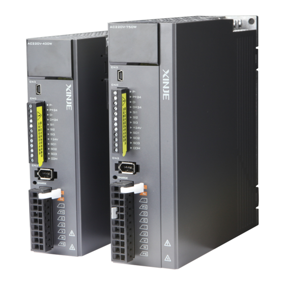
- Page 1 DS5L1 series servo driver User manual WUXI XINJE ELECTRIC CO., LTD. Data No. SC5 05 20200929 1.0...
- Page 3 Basic explanation Thank you for purchasing Xinje DS5L1 series servo driver products. This manual mainly introduces the product information of DS5L1 series servo driver and MS series servo motor. Before using the product, please read this manual carefully and connect the wires on the premise of fully understanding the contents of the manual.
- Page 4 Safety Precautions PrePrecaPrecautio Be sure to review this section carefully before use this product. In precondition of security, wire the product correctly. Before using this product, please read this part carefully and operate after fully understanding the use, safety and precautions of the product. Please connect the product correctly on the premise of paying great attention to safety.
- Page 5 Operation Cautions 1. Do not touch the rotating part of the motor after the driver is running. There is a danger of injury. 2. Please pay attention to the test run of the motor once, do not connect the motor with the machine, there is the possibility of injury.
-
Page 7: Table Of Contents
2.2.2 Installation cautions ........................14 2.2.3 Installation environment ........................ 15 2.3 S ......................... 16 ERVO CABLE INSTALLATION 2.3.1 Cable selection ..........................16 2.3.2 Xinje cable specification ........................17 2.4 S ........................... 19 ERVO DRIVER DIMENSION 2.5 S ........................... 20 ERVO MOTOR DIMENSION 3 SERVO SYSTEM WIRING ........................ - Page 8 5.1 C ....................37 ONTROL MODE SELECTION AND SWITCHING 5.1.1 Control mode selection ........................37 5.1.2 Control mode switching ........................38 5.2 B ..........................39 ASIC FUNCTION SETTING 5.2.1 Jog operation ..........................39 5.2.2 Servo enable setting ........................40 5.2.3 Rotation direction switching ......................41 5.2.4 Stop mode ............................
- Page 9 6.6.1 Overview ............................111 6.6.2 Notes ............................. 111 6.6.3 Operation steps ..........................111 6.6.4 Inertia mode and related parameters ..................112 6.6.5 Recommended inertia ratio parameters..................112 6.6.6 Adaptive parameters effect ......................113 6.6.7 Invalid parameters when adaptive effective ................113 6.7 V ...........................
-
Page 10: Confirmation On Product Arrival
Is the motor code the same with the Check the motor code marked on the nameplates of the code in drive? servomotor and the parameter U3-00 on the servo drive. If any of the above is faulty or incorrect, contact Xinje or an authorized distributor. -
Page 11: Selection Of Servo System
Selection of servo system 1.1 Selection of servo driver 1.1.1 Model name DS5 L1-2 - PTA Encoder type Display Product name Display Communication Servo driver encoder Rated output power Display Product series Display 100W Compact model 200W 400W Rated input voltage Display 750W AC 220V... -
Page 12: Performance Specification
1.1.3 Performance specification Servo unit DS5L1 series servo driver Applicable encoder Standard: 17-bit/23-bit communication encoder Input power supply DS5L1-2□P□-PTA: single phase AC200-240V, 50/60Hz Three-phase full-wave rectifier IPM PWM control sinusoidal current Control mode drive mode Using -10~+40 ℃ temperature Storage -20~+60 ℃... -
Page 13: Description Of Each Part
MS6S–60 C S 30 B Z 1 - 2 0P4 Display Inertia Display Base no. Symbol Product name MS6S Low inertia 40 flange Magnetic Encoder MS6G 60 flange Medium inertia Photoelectric encoder MS6H High inertia 80 flange Symbol Display Symbol Shaft Encoder Rated speed (rpm) -
Page 14: Cable Selection
For 80 and below flange motors with suffix S01, the brake cable model shall be selected: CB-P03-length. Suitable for MS5 motor with suffix S02: CMBT-W07-M-length. The standard wiring length of Xinje is 3m, 5m, 8m, 12m, 16m and 20m. -
Page 15: Description Of Each Part
1.3.2 Description of each part Encoder cable (1) Pin definition of encoder on servo driver side Pin definition Connector appearance Definition 485-A 485-B (2) Cable connection of encoder on motor side Pin definition Connector pins Suitable model Definition Battery + Battery - Shielded cable MS5-40, 60, 80 flange... -
Page 16: Selection Of Other Accessories
(2) Power cable connection on motor side Pin definition Connector pins Suitable model Definition Match -S01 motor Definition Match -S01 motor brake Definition Match MS5-S02 small aviation plug motor Definition Match MS5G series 130 flange 850W non-brake motor Brake pins: The cable including pin BK+, BK- is used for the brake motor. - Page 17 The following table is the recommended specifications of external regenerative resistance for each type of motor. External regenerative External regenerative Rmin resistance resistance Servo driver model (Not less than this value) (Recommended (Recommended power resistance value) values) DS5L1-20P1-PTA 50Ω 50Ω-100Ω Above 200W DS5L1-20P2-PTA DS5L1-20P4-PTA...
-
Page 18: Installation Of Servo System
Installation of servo system 2.1 Servo driver installation 2.1.1 Installation site Please install it in the installation cabinet without sunshine or rain. Do not use this product near corrosive and flammable gas environments such as hydrogen sulfide, chlorine, ammonia, sulfur, chlorinated gas, acid, alkali, salt, etc. ... -
Page 19: Servo Motor Installation
at least 50mm above and below each servo drive. Install cooling fans above the servo drives to avoid excessive temperature rise and to maintain even temperature inside the control panel. Environmental Conditions in the Control Panel Servo driver working ambient Temperature: -10~40 ℃ ... -
Page 20: Installation Cautions
2.2.2 Installation cautions Item Description ◆ Before installation, please wipe the "rust-proof agent" of the extension end Antirust treatment of the servo motor shaft, and then do the relevant rust-proof treatment. ◆ It is forbidden to impact the extension end of the shaft during installation, otherwise the internal encoder will be broken. -
Page 21: Installation Environment
When using in places where water droplets are dropping, please use it on the basis of confirming the protection level of servo motor. (except for the shaft-through part) When oil droplets will drip into the shaft-through part, please specify the servo motor with oil seal. water Conditions for use of servo motors with oil seals: solutions... -
Page 22: Servo Cable Installation
If the cable is used in general occasions, please select the cable from other manufacturers (2.3.2 specifications of Xinje cable) in strict accordance with the specifications given by Xinje. If the cable is used in unconventional occasions, please select the cable according to the actual working conditions to be superior to the existing specifications of Xinje. -
Page 23: Xinje Cable Specification
Select cables (special cables) that meet the use conditions. 2.3.2 Xinje cable specification 1. Material composition of Xinje cable Cross section of cable (encoder, power cable), corresponding introduction of wire skin material, wire diameter, wire core material shielding material, etc. - Page 24 2. Cable diameter specification type Encoder cable Power cable power 100W 4*0.2mm² +2*0.3mm² 4*0.75mm² 200W 4*0.2mm² +2*0.3mm² 4*0.75mm² 400W 4*0.2mm² +2*0.3mm² 4*0.75mm² 750W 4*0.2mm² +2*0.3mm² 4*0.75mm² 3. Cable performance specification Performance Normal cable High flexible cable Ordinary temperature -20℃~80℃ -20℃~80℃ resistance Encoder cable withstand 1000V/min...
-
Page 25: Servo Driver Dimension
2.4 Servo driver dimension DS5L1-20P1-PTA, DS5L1-20P2-PTA, DS5L1-20P4-PTA Unit: mm AC220V~400W CHARGE DS5L1-20P7-PTA Unit: mm AC220V~750W CHARGE... -
Page 26: Servo Motor Dimension
2.5 Servo motor dimension 40 series motor installation dimensions Unit: mm -0.1 25±0.5 LA± 1 Inertia Motor model With level Normal brake MS5S-40ST-C□00330□□-20P1-S01/S02 89.5 inertia 60 series motor installation dimensions Unit: mm LA± 1 Inertia Motor model Series With level Normal... - Page 27 80 series motor installation dimensions Unit: mm 35±0.5 15,5 -0,1 LA± 1 Inertia Motor model Series With level Normal brake MS5S-80ST-C□02430□□-20P7-S01/S02 inertia MS5S-80ST-C□03230□□-21P0-S01/S02 MS5H-80ST-C□02430□□-20P7-S01/S02 High inertia series MS5H-80ST-C□03230□□-21P0-S01/S02 MS-80ST-T02430□□-20P7 MS-80ST-T03520□□-20P7 MS6S-80C□30B□1-20P7 MS6S-80C□20B□1-20P7 inertia series MS6H-80C□30B□1-20P7 High MS6H-80C□20B□1-20P7 inertia 130 series motor installation dimensions Unit: mm 18.5 0 -0.1...
-
Page 28: Servo System Wiring
Servo system wiring Servo driver interface wiring recommended wire, as shown in the following table: Cable Encoder cable Power cable Power supply wiring Power 100W 4*0.2mm² +2*0.3mm² 4*0.75mm² 2*0.75mm² 200W 4*0.2mm² +2*0.3mm² 4*0.75mm² 2*0.75mm² 400W 4*0.2mm² +2*0.3mm² 4*0.75mm² 2*0.75mm² 750W 4*0.2mm²... -
Page 29: Main Circuit Wiring
3.1 Main circuit wiring 3.1.1 Servo driver terminal arrangement RS232 port CN0: pulse, direction, I/O signal interface CN2: encoder interface Power supply Regenerative resistance Motor wiring 3.1.2 Main circuit terminal DS5L1-20P1-PTA, DS5L1-20P2-PTA, DS5L1-20P4-PTA Terminal Function Explanation Power supply input of Single phase AC 200~240V, 50/60Hz main circuit ●... -
Page 30: Cn0, Cn2 Terminal
DS5L1-20P7-PTA Terminal Function Explanation Power supply input of Single phase AC 200~240V, 50/60Hz main circuit ● Vacant terminal Connect the motor U, V, W, Motor terminals Note: the ground wire is on the terminal, please check it before power on! Internal regenerative Short P+ and D, disconnect P+ and C... -
Page 31: Communication Port
(2) Servo pulse input port is ON at 10mA. (3) In order to resist interference, twisted-pair shielding wire must be used. (4) If the controller is Xinje PLC, the rated current of the pulse output port is 50mA. According to... -
Page 32: Input Signal
this data, it can be judged that one pulse theoretically can drive at most five servos. It is recommended not to exceed 3. 3.2.2 SI input signal Please use a relay or an open collector transistor circuit to connect. When using relay connection, please select the relay for small current. - Page 33 Voltage: DC 30V (maximum) Current: SO1 DC 500mA (maximum) (400W and below servo can support) SO (others) DC 50mA (maximum)
-
Page 34: Operate Panel
Operate panel 4.1 Basic operation 4.1.1 Operating panel description Button Operation STA/ESC Short press: state switch, state return Short Press: The display data increases Long press: The display data increases continuously Short Press: The display data decreases Long press: The display data decreases STA/ESC ENTER continuously... -
Page 35: Operation Display
4.2 Operation display Speed torque control mode 1. Digit display contents Digit data Display contents P5-39 When the actual speed of the motor is the same as the command speed, Same speed detection turn on the light. (/V-CMP) Detection Width of Same Speed Signal: P5-04 (Unit: rpm) When the speed is controlled, when the torque exceeds the set value, P5-42 turn on the light. -
Page 36: Group Umonitor Parameter
Positioning completion COIN Positioning near NEAR Rotate detection TGON 1. Digit display contects Digit data Display contents P5-38 In position control, when the given position is the same as the actual Positioning completion position, turn on the light. (/COIN) Location Completion Width: P5-00 (Unit: Instruction Pulse) In position control, when the given position is the same as the actual P5-36 position, turn on the light. - Page 37 U0-21 input signal 1 distribution Segment Segment Description Description code code /S-ON servo enable /P-CON proportion action instruction /P-OT prohibition of forward /N-OT prohibition of reverse drive drive /ALM-RST alarm reset /P-CL forward side external torque limit /N-CL reverse side external /SPD-D internal speed selection...
- Page 38 U0-23 output signal status U0-23 output signal 1 distribution Segment Segment Description Description code code Positioning completion hold Positioning completion(/COIN) (/COIN_HD) Same speed detection(/V-CMP) Rotate detection(/TGON) Ready (/S-RDY) Torque limit(/CLT) Speed limit detection(/VLT) Break lock(/BK) Warn (/WARN) Output near(/NEAR) Note: When reading through communication, the binary numbers read from right to left correspond to the position of / COIN_HD, / COIN, 0 means that the position signal is not output, 1 means that the position signal has output.
-
Page 39: Group Fauxiliary Function Parameters
U0-24 output signal 2 distribution Segment Segment Description Description code code Alarm (/ALM) Speed arrived (/V-RDY) Customized output 1 Customized output 2 /Z phase /MRUN Reserved Xnet bus error Reserved Reserved Note: When reading the state through communication, the binary numbers correspond to /ALM position in turn from right to left. -
Page 40: Group F1
2. Resume to default setting(F0-01) Set F0-01=1 when enabler is shut down, press ENTER to resume to default settings, no need to cut power. 3. Clear the position offset(F0-02) Set F0-02=1 to clear the offset. 4. Clear up historical alarm records(F0-04) Set F0-04=1 can clear up historical alarm records from U1-14 to U1-53. -
Page 41: Fault Alarm Handling
Default Setting Parameter Meaning Unit Change Effective setting range Servo P3-18 JOG speed 1rpm At once 0~1000 3. Current sampling zero-correction (F1-02) When the servo driver is self-renewed or the motor runs unsteadily after a long time, the user is advised to use the current sampling zero-correction function. -
Page 42: Parameter Setting Example
4.6 Parameter setting example An example is given to illustrate the operation steps when the content of parameter P3-09 is changed from 2000 to 3000. Step Panel display Used buttons Operations No operation Press STA/ESC Press INC for three times to show P3-00 Press ENTER, the last 0 will flash Press INC for 9 times... -
Page 43: Operation Of Servo System
Operation of servo system 5.1 Control mode selection and switching 5.1.1 Control mode selection Servo can combine two control modes and switch between them. By switching freely between mode 1 and mode 2 through the / C-SEL signal, more complex control requirements can be satisfied. User parameter Control mode Reference... -
Page 44: Control Mode Switching
5.1.2 Control mode switching Control mode switching means that when the servo is enabled, that is, when the servo panel displays run, the working mode of the servo driver can be switched between mode 1 and mode 2 through the external input signal /C-CEL. -
Page 45: Basic Function Setting
Inching operation can be carried out by panel group F parameters or our upper computer debugging software xinje servo tuner. Inching operation can be divided into two modes: inching operation and trial operation. Inching operation is closed-loop control, trial operation is open-loop control, and general steps are trial operation first, and then inching operation. -
Page 46: Servo Enable Setting
ON/OFF: enable the jog mode. : forward run and reverse run. The steps of inching through Xinje servo tuner Open the software XinjeServo Tuner, set the jog speed P3-18, select test run/jog run button, click ON. Then click forward or reverse button to run. -
Page 47: Rotation Direction Switching
5.2.3 Rotation direction switching Related parameter Default Parameter Meaning Unit Range Modify Effective setting Definition of rotation direction Power on P0-05 Servo bb 0- positive mode again 1- negative mode The user can change the rotation direction of servo motor through parameter P0-05. It is specified that the "forward rotation"... - Page 48 Parameter Value Meaning inertia stop and maintain the inertia operation state after stopping. P0-27/ deceleration brake stop and maintain the inertia operation state P0-29 after stopping. Note: (1) P0-27 / P0-29 = 0, inertia stops, and maintains inertia operation state after stopping. When the servo is off and the alarm occurs, the motor starts to stop by inertia until the speed is less than P5-03, and then it turns to free stop.
-
Page 49: Power-Off Brake
No need to connect P5-22/P5-23=n.0010 external input SI□ terminal has signal P5-22/P5-23=n.000□ valid input SI□ terminal has no signal P5-22/P5-23=n.001□ input Parameter settings in forward limit signal /POT and reverse limit signal /NOT can not be set to the same terminal input at the same time. Direction Meet the limit Operation status... - Page 50 Related parameter Default Parameter Meaning Unit Setting range Modify Effective setting P5-44 Brake interlock/BK n.0000 n.0000~n.00ff Anytime At once At once Servo OFF delay P5-07 Servo bb 0~65535 time Brake command At once P5-08 Servo bb 20~10000 output speed Brake command wait At once P5-09...
- Page 51 (1) When SO terminal is used to control holding brake, when servo enable is on, holding brake power is on and motor is in rotatable state; (2) If the motor fails to rotate during the debugging of the new machine, please confirm whether the holding brake is open.
-
Page 52: Braking Setting
5.2.6 Braking setting When the servo motor is driven by the generator mode, the power returns to the servo amplifier side, which is called regenerative power. Regenerative power is absorbed by charging the smoothing capacitor in the servo amplifier. After exceeding the rechargeable energy, the regenerative resistance is used to consume the regenerative power. -
Page 53: Position Control
2. Recommended brake resistance specifications External regeneration External regeneration min resistance (cannot be resistance resistance Servo driver model less than this value) (recommended (recommended power resistance) value) DS5L1-20P1-PTA 50Ω 50Ω-100Ω Above 200W DS5L1-20P2-PTA DS5L1-20P4-PTA 40Ω 40Ω-100Ω Above 500W DS5L1-20P7-PTA Note: (1) The smaller the resistance is, the faster the discharge will be, but it is easy to break down the resistance if it is too small. - Page 54 occur. Related parameters Default Setting Parameter Meaning Unit Modify Effective setting range Servo At once P0-11 Pulse numbers per rotation *1 0~9999 Servo At once P0-12 Pulse numbers per rotation *10000 0~9999 Servo At once P0-13 Electronic gear ratio (numerator) 0~65535 Servo At once...
- Page 55 unit equivalent of 0.01mm is more accurate than the unit equivalent of 0.1mm. 3. Example of setting the electronic gear ratio Ball screw Round table Belt + pulley Load shaft Load shaft Load P: pitch steps Name shaft 360 ° 1rotate = 1 rotate = command unit...
- Page 56 Signal Default Suitable Parameter Meaning Modify Effective name setting mode Positioning complete P5-37 /COIN-HD n.0000 Anytime At once holding Positioning complete P5-38 /COIN n.0000 Anytime At once output Refer to section 3.2.2 for hardware wiring details. If it is necessary to output signal from SO2, P5-37 and P5-38 are set to n.0002/0012. Note that an SO terminal can only be used as a signal function.
- Page 57 When instruction ends motor speed is under the rotation detection speed (P5-03) and absolute deviation is less than P5-00, COIN signal output. instruction, absolute deviation value under P5-00, it outputs COIN signal. COIN maintains P5-02 time, COIN-HOLD signal is output. 2.
- Page 58 Default Parameter Meaning Unit Range Change Effective setting Near signal output Command P5-06 0~65535 Anytime At once width unit Signal Default Suitable Parameter Meaning Modify Effective name setting mode P5-46 /NEAR n.0000 Positioning near Anytime At once Refer to section 3.2.2 for hardware wiring details. If it is necessary to output from the SO2, P5-46 can be set to n.0002/0012.
- Page 59 1. /INHIBIT terminal effectiveness description Parameter setting Signal/INHIBIT terminal Signal/INHIBIT terminal input status status logic P5-32=n.0000 No external terminal input SI□ terminal has no signal input P5-32=n.000□ Invalid SI□ terminal has signal input P5-32=n.001□ P5-32=n.0010 No external terminal input SI□ terminal has signal input P5-32=n.000□...
- Page 60 (such as PLC) and feedback pulse of servo unit in position mode. Its unit is 1 command unit, which is related to the command unit determined by electronic gear ratio. In position control, when the deviation pulse exceeds a certain limit value, an alarm will occur, and this threshold value is the deviation pulse limit value.
- Page 61 5.3.1.8 Reference origin 1. Find the reference origin To find out the physical origin of working table and make it as the coordinates origin of point position control. Users can select finding reference origin at forward or reverse side. Function setting: Default Parameter Meaning...
-
Page 62: Position Control (External Pulse Command)
/N-OT /P-OT Speed P4-01 Speed P4-01 ① Direction CW Direction CCW Stop mode Stop mode ② P0-28 P0-28 Speed P4-02 Speed P4-02 ③ Direction CW Direction CCW Z signal quantity Z signal quantity P4-00 P4-00 Reference origin Reference origin of reverse side of forward side Sequential diagram of finding reference origin on forward side: ①... - Page 63 P0-94*1 + P0-95 *10000 P0-09 Pulse command setting You can set the command direction and 5.3.2.2 filter time of low-speed pulse respectively 5.3.2.1 External pulse position mode Setting Parameter Meaning Modify Effective value P0-01 Control the position by external pulse Servo OFF At once 5.3.2.2 Forward direction of pulse instruction and pulse form...
-
Page 64: Position Control (Internal Command)
1:AB 2:P+D 4. Pulse specification Highest input Pulse specification Voltage Forward current frequency Differential signal 500Kpps 3.3~5V <25mA Low speed pulse Open collector 200Kpps <25mA 5.3.3 Position control (Internal command) Parameter Overview Reference chapter P0-01 control mode selection Set to 5: internal position 5.3.3.1 mode P4-03 internal position mode... - Page 65 5.3.3.1 Internal position mode Setting Parameter Meaning Change Effective value Position control by preset values of internal registers P0-01 Servo bb At once in servo units 5.3.3.2 Internal position mode setting Default Suitable Parameter Function Unit modify Effective setting mode Internal position —...
- Page 66 After the drive output 1-segment position After the drive output 1-segment position command, it will not wait for the completion of command, it will not wait for the completion of motor positioning, and start the next position motor positioning, but pass the adjust time, and command at once.
- Page 67 n.xx□x Description Take setting two segments as an example, t1 = p4-16 in the figure. 1. Note that as shown in the figure, in this mode, the set adjustment time actually does not work. As long as the previous position command has been sent out, the next command will...
- Page 68 t1 = p4-16 in the figure. 1. /CHGSTP rising edge triggers the first segment and falling edge triggers the second segment. Where, if the first segment position is required to operate completely, the /CHGSTP signal remains on until the end of the first segment. /CHGSTP 2.
- Page 69 the range is 13 (segment 5 position) segment 14 (segment 6 position) 1~16. 15 (segment 7 position) 16 (segment 8 position) Note: the rising edge of P5-35 step change signal triggers each position (the rising edge is invalid during operation). 1.
- Page 70 5.3.3.3 Position segment 1 to 35 parameter settings Default Parameter Meaning Unit Range Change Effective setting Pulse number Servo 1 pulse At once P4-10+(n-1)*7 -9999~9999 (low bit) Pulse number Servo At once 10000 pulses P4-11+(n-1)*7 -32767~32767 (high bit) Servo At once Speed P4-12+(n-1)*7 0.1rpm...
- Page 71 Parameter Meaning Default setting Range Change Effective P4-04 Effective segment Servo bb At once 0~35 There are 35 sections in total in the internal position. If 10 sections need to be operated and 5 sections need to be operated switched for use due to process requirements, the effective segment can be set. For example, parameters are set for sections 1-10, and P4-04 is set to 5, that is, the position of section 1-5 is valid;...
- Page 72 effects, as follows: Change step Skip the present mode Actions segment P4-03 n.xx□x Cancel current segment, execute the next segment at once Cancel current segment, execute the next segment when the change step signal is ON Cancel current segment, execute the next segment at once Cancel current segment, set the F2-09 again /Z-CLAMP The current segment is cancelled and the next segment is...
-
Page 73: Speed Control
5.4 Speed control 5.4.1 Speed mode general control 5.4.1.1 Soft start Defaulted Parameter Meaning Unit Range Modify Effective setting Soft Start P3-09 0~65535 Servo bb At once Acceleration Time Soft Start P3-10 0~65535 Servo bb At once deceleration Time Soft start acceleration and deceleration time is suitable for mode 3/4/7. Smooth speed control can be carried out when step speed instruction is input or internal setting speed is selected. - Page 74 3. Parameter setting Default parameter Meaning Unit Range Change Effective setting P3-13 Zero clamp speed 0~300 Servo bb At once P3-12 Zero clamp mode 0~3 Servo bb At once P3-12 setting Contents ZCLAMP input signal is ON, forced speed command is 0, when the speed below P3-13, switch to position mode and the servo lock in this position.
-
Page 75: Speed Control (Internal Speed)
P1-22 Contents First-order Inertial Filter Smooth filter Position command acceleration and Smooth filter of position instruction deceleration filter Command pulse frequency Command pulse frequency Before filtering Before filtering After filtering After filtering 100% 100% 63.2% 36.8% P1-23 P1-23 P1-23 P1-23 5.4.2 Speed control (internal speed) Parameter Overview... - Page 76 Servo unit /SPD-D /SPD-A Input Servo motor /SPD-B Speed selection SPEED1 P3-05 SPEED2 P3-06 SPEED3 P3-07 No need external speed or Run the motor pulse generator at set speed User parameter Related parameter Defaulted Parameter Meaning Unit Range Modify Effective setting Internal speed 1...
- Page 77 (3) 0/1 of the above table represent the validity of the signal. The 0-bit terminal input is invalid. 1 is the terminal input valid. 2. Terminal effectiveness description The following table takes /SPD-D as an example, /SPD-A, /SPD-B signals are the same. Signal/SPD-D terminal Parameter setting Signal/SPD-D terminal input status...
- Page 78 5.4.3 Speed control (pulse frequency command) Reference Parameter Overview chapter P0-01 Control mode selection Set to 7: external pulse speed mode 5.4.3.1 P0-10 Pulse command form Set pulse form 5.3.2.2 0-CW/CCW 1-AB 2-P+D P0-15 Command pulse frequency at Determine the linear relationship between the 5.4.3.3 rated speed command pulse frequency and the speed...
-
Page 79: Torque Control
5.5 Torque control 5.5.1 Torque general mode 5.5.1.1 Internal speed limit of torque control Default Parameter Meaning Unit Range Modify Effective setting internal forward Motor rated P3-16 speed limit in torque Anytime At once 5~65535 control mode internal reverse speed Motor rated P3-17... -
Page 80: Absolute Value System
5.5.2.2 Internal torque command Parame Default Effe Meaning Unit Range Modify setting ctive Internal torque 1% rated Anyti -1000~+1000 P3-33 command torque once The unit of this parameter is 1% of the rated torque. For example: P3-33=50, motor forward run with 50% of the rated torque; P3-33= -20, motor reverse run with 20% of the rated torque. -
Page 81: The Upper Limit Of Turns
(4) Close the cover of the battery unit (5) After replacing the battery, in order to remove the "Encoder Battery Alarm (E-222)" display, please do clear alarm twice (F0-00=1). (6) Connect the power supply of the servo unit again; (7) Make sure the error display disappears and the servo unit can operate normally. 5.6.3 The upper limit of turns The upper limit of rotating cycles can be used for position control of gyroscopes such as turntables. -
Page 82: Auxiliary Functions
Because it can only rotate in one direction, after a certain period of time, the number of revolving cycles will always exceed the upper limit of absolute value encoder. Resolution Rotating Circle Servo motor (single-circle Serial Data Operation of overtime series data) Output range... -
Page 83: Torque Limit
P0-74 (/ms) default Driver model parameter DS5□-20P1-PTA 2000 DS5□-20P2-PTA 3000 DS5□-20P4-PTA 3000 DS5□-20P7-PTA 5000 5.7.2 Torque limit 1. Internal torque limit Default Parameter Meaning Unit Range Modify Effective setting Internal Forward P3-28 0~300 Anytime At once torque limit Internal reverse P3-29 0~300 Anytime... -
Page 84: Speed Limit
4. Output torque up to limit value signal Parame Signal Default Suitable Modify Effective Meaning name setting mode Torque Output signal when Anytime At once P5-42 limit n.0000 motor output torque up /CLT to P3-28, P3-29. No terminals are assigned by default. The parameter range is 0000-0014, which is assigned to the output interface through parameter P5-42. -
Page 85: Output Terminal Function
P5-34.2=3 basic filtering time is 3ms P5-18=10 filtering time multiple is 10 So the total filtering time is P5-34.2 * P5-18=3ms*10=30ms 5.7.4.2 Output terminal distribution 1. Output signal distribution Parameter Parameter Meaning Set value Meaning Not distribute to terminal input n.0000 Output always open signal from n.000x... - Page 86 1. No terminal output signal is assigned by default. The parameter range is 0000-0014, which is allocated to other output terminals through parameter P5-40. 2. When the speed of the servo motor is higher than the set value of P5-03, the signal that the servo is rotating is considered.
- Page 87 5.7.5.4 Warn output (/WARN) Set the alarm output threshold, when the current speed is higher than the warning speed, output / WARN. Default Parameter Meaning Unit Range Modify Effective value Forward warning Motor P3-19 0~65535 Servo bb At once speed related Reverse warning Motor...
- Page 88 Encoder Z phase signal P5-48=n.0011 SO1 output P5-48=n.0001 SO1 output 5.7.5.7 User-defined output signal User can define 2 outputs. The defined method is SOx output when A>B or A<B. A is 9 activating conditions; B is user-defined comparison value. User-defined output 1: The trigger condition of user-defined output 1 Default Trigger condition...
- Page 89 User-defined output 2: The trigger condition of user-defined output 2 Default Trigger trigger condition Unit Suitable mode Change Effective condition setting P5-14 below Related table: trigger All the modes Anytime At once optional trigger condition condition The comparison value for the trigger condition of user-defined output 2 Unit Default setting Range...
-
Page 90: Input Terminal Function
5.7.5.8 Other SO terminal function Terminal name Description Chapter /COIN-HD Positioning completion hold 5.3.1.2 /COIN Positioning end 5.3.1.2 /CLT Torque limit detection 5.8.2 /VLT Speed limit detection 5.5.1.3 /MRUN Internal position mode motion start 5.3.2.7 /V-RDY Speed arriving signal 5.4.1.3 /PREFA Internal position selection signal 5.3.2.1... -
Page 91: Time Limit Curve Of Overload Protection
5.7.7 Time limit curve of overload protection The time limit curve of overload protection is only used for the judgment of alarm output and the protection of overload operation. It is recommended to use it within the continuous operation stage of torque speed curve. - Page 92 Applicable model (motor code) 5072 5872 9072 9872 Applicable model (motor code) 5033 9033 4031 4032 4042 5042 4044 5044 5078 5079 5077 5877 9077 9877...
-
Page 93: Servo Gain Adjustment
Servo gain adjustment 6.1 Overview of servo gain adjustment 6.1.1 Overview and process The servo driver needs to drive the motor as fast and accurately as possible to track the instructions from the upper computer or internal settings. In order to meet this requirement, the servo gain must be adjusted reasonably. -
Page 94: The Difference Of These Adjustment Modes
Note: * marked as version 3730, the version before 3730 is in adaptive mode when out of factory. 6.1.2 The difference of these adjustment modes Adjustment modes are divided into adaptive and auto-tuning, and their control algorithms and parameters are independent. Among them, the auto-tuning mode is divided into three functions: fast adjustment, automatic adjustment and manual adjustment. - Page 95 In this way, the response of setting parameters is fast, and the overshoot is restrained. Load type Explanation Synchronous The adjustment is suitable for the mechanism with lower rigidity such as synchronous belt belt mechanism. It is suitable for the adjustment of high rigidity mechanism such as ball screw Lead screw mechanism.
-
Page 96: Torque Disturbance Observation
Load inertia ratio P0-07: 500% speed loop gain P1-00: 200 speed loop gain P1-00: 800 speed loop gain P1-00: 800 speed loop integral P1-01: 3300 speed loop integral P1-01: 825 speed loop integral P1-01: 825 position loop gain P1-02: 200 position loop gain P1-02: 700 position loop gain P1-02: 700 Model loop gain P2-49: 300... -
Page 97: Notes
6.2.2 Notes Occasions where inertia cannot be presumed Mechanical systems can only operate in one direction The occasion where inertia presumption is easy to fail Excessive load moment of inertia The running range is narrow and the travel is less than 0.5 circles. ... - Page 98 auto-tuning max speed Inertia identification P2-18 1~20000 Anytime At once initial inertia ratio The recommended parameters of P2-17 are 500 rpm or more. Low instruction speed will lead to inaccurate identification of inertia ratio. 2. Execute the inertia identification Before inertia identification, please confirm the direction of servo rotation by using F1-00 jog motion function.
- Page 99 ④ overshoot ① The presumed inertia trip is too small. It is Driver internal suggested that the minimum for P2-15 should no be Err-3 trip calculation Contact us less than 50 (0.5 cycles). If the trip is too small, the error identification of inertia ratio will be inaccurate.
- Page 100 3. Set the auto-tuning interface 4. Click ok to start inertia identification.
-
Page 101: Fast Adjustment
Note: (1) If the auto-tuning interface is closed directly, the driver only configures inertia ratio parameters. (2) The detailed steps of XinJeServo's presumptive inertia refer to XinJeServo's help document. 6.3 Fast adjustment 6.3.1 Overview Fast adjustment needs to set the moment of inertia of load first, then turn off the adaptive function. If the inertia does not match, it will cause oscillation alarm. - Page 102 3183 2893 2652 2448 2273 2122 1989 1872 1768 1675 1591 1414 1273 1157 1100 1061 1300 1500 1800 2100 2400 2700 3000 3100 1000 3200 Rigidity level P2-35 P1-00 P1-01 P1-02 P2-49 P0-04 Torque Speed loop speed loop Position loop Model loop Rigidity level...
-
Page 103: Notes
2400 2400 6000 2450 2450 6000 2500 2500 6000 2600 2600 6000 The rigidity level should be set according to the actual load. The larger the P-04 value, the greater the servo gain. If there is vibration in the process of increasing the rigidity level, it is not suitable to continue to increase. -
Page 104: Auto-Tuning
6.4 Auto-tuning 6.4.1 Overview Auto-tuning is divided into internal instruction auto-tuning and external instruction auto-tuning. Auto-tuning (internal instruction) refers to the function of automatic operation (forward and reverse reciprocating motion) of servo unit without instructions from the upper device and adjusting according to the mechanical characteristics in operation. - Page 105 3. Press ENTER, panel display is iat--, servo is in enabled status right now; 4. Press INC or DEC, panel display is tune and flashing, enter auto-tuning status; 5. Driver will automatically send pulse instructions, if the auto-tuning is successful, the panel shows done and flashing.
- Page 106 3. set the auto-tuning interface...
- Page 107 4. click ok to estimate the inertia. 5. set the auto-tuning parameters Load type Description Fit for the adjustment of lower rigidity mechanism such as synchronous Synchronous belt belt mechanism. It is suitable for adjustment of higher rigidity mechanism such as ball Screw rod screw mechanism.
- Page 108 In the use of positioning, we should pay attention to adjusting without Fast positioning overshoot. Besides gain adjustment, the model loop gain and notch filter (control overshoot) are automatically adjusted. 6. Start auto-tuning 7. Wait for the end of the auto-tuning...
-
Page 109: External Instruction Auto-Tuning Steps
6.4.5 External instruction auto-tuning steps Driver panel auto-tuning steps 1. The inertia identification is carried out and the step of inertia estimation please refers to the driver panel inertia estimation (6.2.4 operation step) 2. Shut down adaptive function (P2-01.0 sets to 0), power on again 3. - Page 110 2. Select jog or manual setting to configure the trip of inertia identification. 3. Set the auto-tuning interface 4. Click ok to start the inertia identification.
- Page 111 5. Configure the auto-tuning parameters Auto-tuning mode Description Make a soft gain adjustment. Besides gain adjustment, notch filter is Soft automatically adjusted. Make special adjustment for positioning purpose. Besides gain adjustment, Rapid positioning the model loop gain and notch filter are automatically adjusted. In the use of positioning, we should pay attention to adjusting without Rapid positioning overshoot.
- Page 112 with higher rigidity. 6. Start auto-tune 7. Open the servo enable, then click ok.
-
Page 113: Related Parameters
8. The upper device starts to send pulses, wait the completion of auto-tuning. 9. Auto-tuning is finished, click ok. 6.4.6 Related parameters The following parameters may be modified during auto-tuning. Do not change them manually during auto-tuning. The influence of numerical Parameter Name Property... -
Page 114: Manual Adjustment
P2-64 Active vibration suppression filter time 1 P2-65 Active vibration suppression filter time 2 The second group of active vibration P2-66 damping Second group active vibration suppression P2-67 frequency First notch switch P2-69.0 Second notch switch P2-69.1 First notch frequency P2-71 First notch attenuation P2-72... -
Page 115: Adjustment Steps
Pulse instruction Model loop Speed Torque feedforward feedforward Position Speed control loop control loop Speed Servo motor instruction Position Speed Torque Error Current loop gain control Kv, instruction counter control filter Tf Current loop Speed loop Position loop encoder Upper device Servo unit Position control loop diagram (turn on the model loop) Servo unit consists of three feedback loops (current loop, speed loop and position loop) from inside to... -
Page 116: Gain Parameters For Adjustment
6.5.3 Gain parameters for adjustment The gain parameters that need to be adjusted: P1-00 Speed Loop Gain P1-01 Integral Time Constant of Speed Loop P1-02 position loop gain P2-35 Torque Instruction Filtering Time Constant P2-49 Model Loop Gain Speed loop gain Because the response of the speed loop is low, it will become the delay factor of the outer position loop, so overshoot or vibration of the speed command will occur. -
Page 117: Adaptive
Filter time constant of torque instruction When machine vibration may be caused by servo drive, it is possible to eliminate vibration by adjusting the filtering time parameters of the following torque instructions. The smaller the numerical value, the better the response control can be, but it is restricted by the machine conditions. When vibration occurs, the parameter is generally reduced, and the adjustment range is suggested to be 10-150. -
Page 118: Inertia Mode And Related Parameters
6.6.4 Inertia mode and related parameters The adaptive default parameter is defined as small inertia mode. If the load inertia far exceeds the allowable load inertia of the motor (such as 60 times inertia of the 60 motor), the adaptive large inertia mode can be turned on. -
Page 119: Adaptive Parameters Effect
6.6.6 Adaptive parameters effect Parameter Small Default Name Range Effect inertia/large value inertia Reduction can improve the inertia Adaptive speed capability, but it will reduce the P2-05/P6-05 400/200 200-400 loop gain responsiveness, which has a greater impact on the responsiveness. Increase can greatly improve the inertia Adaptive load... -
Page 120: Vibration Suppression
6.7 Vibration suppression 6.7.1 Overview The mechanical system has a certain resonance frequency. When the servo gain is increased, the continuous vibration may occur near the resonance frequency of the mechanical system. Generally in the range of 400Hz to 1000Hz, it caused the gain can not continue to increase. Vibration can be eliminated by automatically detecting or manually setting the vibration frequency. -
Page 121: Vibration Suppression (Pc Software)
5. Press STA/ESC to exit 6. Vibration suppression parameters are automatically written into the second and first notches (the second notches are preferred when there is only one vibration point). The related parameters are detailed in 6.7.7 notch filter. Fault alarm of panel in vibration suppression process Error code Meaning Reasons... -
Page 122: Vibration Suppression (Manual Setting)
5. set the filter width (to see resonance frequencies clearly), find the resonance frequency; 6. Notch parameters need to be set manually. Refer to 6.7.7 notch filter for details. As an example, through the analysis of mechanical characteristics, the resonance frequency is 328 Hz, and the third notch filter can be used. - Page 123 1. F0-12, long press【ENTER】to enter quick FFT function, it will show “E_FFt”. 2. Press 【ENTER】 to enter torque setting interface, it will show the current setting torque, which is the value of P6-89. Press【INC】,【DEC】to increase or decrease torque command. When increasing the torque command, it is recommended to increase it a little bit to avoid severe vibration of the equipment.
-
Page 124: Notch Filter
6.7.7 Notch filter Notch filter can suppress mechanical resonance by reducing the gain at a specific frequency. After the notch filter is set correctly, the vibration can be effectively suppressed and the servo gain can be continuously increased. The principle diagram of notch filter is as follows: mechanical system Amplitude frequency characteristic... - Page 125 n.□□1□ Fifth notch on Default Parameter Meaning Unit Range Change Effective setting P2-71 First notch frequency 5000 Anytime At once 50~5000 Anytime At once P2-72 First notch attenuation 0.1dB 50~1000 Anytime At once P2-73 First notch bandwidth 0~1000 Anytime At once P2-74 Second notch frequency 5000...
-
Page 126: Gain Adjustment
6.8 Gain adjustment 6.8.1 Load shaking The following causes cause load wobble: 1. The instruction is not smooth enough when the load inertia is too large. Countermeasure: (1) Use position instruction smoothing filter P1-25; (2) Optimizing the instructions of the upper device to reduce the acceleration of the instructions; (3) Replace the motor with greater inertia. -
Page 127: Alarm
Alarm 7.1 Alarm code list Historical record: "√" means that historical alarms can be recorded; "○" is not recorded; The column that can be cleared: "√" represents the alarm that can be cleared; "○" represents the alarm that cannot be cleared. Property Servo Whether... - Page 128 Self-Inspection √ √ E-150 Power cable disconnection Servo off Driver thermal power √ √ E-161 overload √ √ Servo run E-165 Anti-blocking alarm Servo run Regenerative resistance √ √ E-200 overload Communication error Servo off √ √ E-220 absolute servo encoder Too many CRC errors in Servo off √...
-
Page 129: Analysis Of Alarm Types
Analysis of alarm types DS5 alarm code format is E-XX□, “XX” means main type, “□” means sub-type. Type Code Description Reasons Solutions EEEE (1) Stable power supply to ensure (1) Voltage fluctuation the stability of power supply EEEE of power supply is Communication voltage. - Page 130 E-028 EEPROM write in Voltage instability or Please contact the agent or the error chip abnormality manufacturer Check the fluctuation of power grid, 220V driver normal voltage range 200V ~ 240V, 380V driver High voltage of power normal voltage range 360V ~ grid 420V.
- Page 131 220V + 10% (380V + 10%), then check the supply voltage; if the supply voltage is normal, then servo state, monitoring U0-05, multimeter measurement voltage * 1.414 > U0-05 (error within 10V), then the servo driver is faulty and needs to be sent back for repair Driver power...
- Page 132 input frequency is too high, and whether the electronic gear ratio is too large. (1) Check the encoder cable or change a new one (2) Set the servo driver to BB state and the driver to U-10. Rotate the motor shaft slowly by Encoder fault hand to see if the value of U-10 changes normally, increasing in...
- Page 133 Rotate the motor shaft slowly by hand to see if the value of U-10 changes normally, increasing in one direction and decreasing in direction (0-9999 cycle display). Disconnect the power supply of driver check Any phase in UVW of connection of the power cable. It Power cable E-150...
- Page 134 wiring. Poor gain adjustment results motor vibration, back Readjustment of gain parameters forth swing abnormal noise. There are servo cross test or motor empty shaft on site, F1-01 trial operation, F1-00 jog run can Driver motor not rotate uniformly; hardware failure; Replace the new driver or motor send malfunction...
- Page 135 servo encoder Check whether the value of U0-54 increases rapidly. If yes, encoder circuit disconnected.Disconnect power supply of the driver, check the connection of the encoder Unconnected encoder cable, if there is cable loosening, cable or poor contact it is recommended to use the multimeter to test the conduction condition;...
- Page 136 Generally, it is the (the driver panel shall problem of the encoder completely off). If the alarm itself, or the power cannot removed, please supply of the encoder is contact the agent or manufacturer unstable Abnormal power on of main control chip of multi-turn absolute value servo encoder...
- Page 137 scrambling number errors the strong and weak current are exceeds the value in wired separately. ② High current equipment is encoder error retry number register P0-56 supplied separately. ③ The grounding is good. Overrun signal If you do not want to alarm detected and the overrun immediately when the overrun E-260...
- Page 138 Power mismatch Match the correct motor and Such as 750W driver E-310 between driver driver, and use it after setting the with 200W motor and motor P0-33 motor code correctly When the motor On the premise that the driver and code read motor are matched and can be...
-
Page 139: Appendix
Appendix Appendix 1. Group P parameters Modification and effective: “○” means modifying when servo OFF and take effect at once. “√” means modifying anytime and take effect at once. “●” means modifying when servo OFF and take effect when power on again. “△”... - Page 140 Definition of rotation direction 1|2|3|4|5|6|7| ● P0-05 5.2.3 8|9|10 0- positive mode 1- negative mode 20P1 : 800 0~5000 1|2|3|4|5|6|7| √ First inertia ratio P0-07 6.2.1 >20P1 : 200 8|9|10 Forward Direction Input Pulse Instruction 0-Forward Pulse ● P0-09.0 5.3.2 Counting 1-Reverse Pulse...
- Page 141 Power Value of Set as 1|2|3|4|5|6| ○ P0-25 1~65535 5.2.6 Discharge Resistance model 7|8|9|10 Discharge resistance Set as 1|2|3|4|5|6| Ω ○ P0-26 1~500 5.2.6 value model 7|8|9|10 Servo shutdown enable stop mode 1|2|3|4|5|6| ○ P0-27 5.2.4 0-Inertial Operation Stop 7|8|9|10 2-deceleration stop Servo Overrun...
- Page 142 1|2|3|4|5|6| √ Blocking alarm speed P0-75 5~9999 5.8.1 7|8|9|10 Absolute Encoder Battery Undervoltage Alarm Switch (firmware version 20160304 and later) 0-used as absolute value 1|2|3|4|5|6| ● P0-79 5.7.1 encoder 7|8|9|10 1-1-used as incremental encoder 2-2-used as absolute value encoder, ignoring multi turn overflow alarm Thermal Power Protection of Motor...
- Page 143 Reference Parameter Function Unit Default value Range Effective Suitable mode chapter position instruction △ P1-25 0.1ms 0~65535 5|6|10 5.3.1.7 smooth filter time P2-XX: Suitable Reference Parameter Function Unit Default value Range Effective mode chapter Disturbance observer switch 1|2|3|4|5|6|7| ○ P2-00.0 6.1.4 8|9|10 0- OFF...
- Page 144 Inertia Identification 8|9|10 Gain of adaptive mode 1|2|3|4|5|6|7| √ speed observer P2-18 1~20000 6.2.4 8|9|10 (standard) Default Suitable Reference Parameter Function Unit Range Effective value mode chapter 20P1 : 100 Adaptive mode 20P2 , 1|2|3|4|5|6|7| ○ P2-19 1~100 6.2.4 20P4 : 70 bandwidth 8|9|10 >=20P7 :...
- Page 145 1|2|3|4|5|6|7| √ Notch filter 2 switch P2-69.1 6.4.6 8|9|10 1|2|3|4|5|6|7| √ Notch filter 3 switch P2-69.3 8|9|10 1|2|3|4|5|6|7| √ Notch filter 4 switch P2-70.0 8|9|10 1|2|3|4|5|6|7| √ Notch filter 5 switch P2-70.1 8|9|10 1|2|3|4|5|6|7| √ First notch frequency P2-71 5000 50~5000 6.7.7 8|9|10...
- Page 146 corresponding to rated speed (5E/5L not support) Analog voltage speed √ filter (5E/5L not P3-02 0.01ms 0~10000 1|2|4 5.4.4 support) Speed instruction input √ dead zone voltage P3-03 0.001v 0~500 1|2|4 5.4.4 (5E/5L not support) V-REF analog speed √ direction(5E/5L not P3-04 1|2|4 5.4.4...
- Page 147 condition for limiting input external torque, the minimum value valid compared with P3-28/P3-29. 2-Torque Feedforward Default Suitable Reference Parameter Function Unit Range Effective value mode chapter analog value corresponding ○ P3-24 0.001V 10000 1500~30000 2|3|4|5|6|7|10 5.5.3 to rated torque Analog Voltage Torque 5.5.3 √...
- Page 148 Default Suitable Reference Parameter Function Unit Range Effective value mode chapter Internal Position-Given Mode Sets Step Change Mode 0-step-changing when signal is ON, recyclable 1-change step at signal rising edge, single step execution 2-starting at Signal rising edge, sequential execution of all, no cycle ○...
- Page 149 Default Suitable Reference Parameter Function Unit Range Effective value mode chapter 8|9|10 Positioning near output Command √ P5-06 1~65535 5|6|10 5.3.1.3 width unit -500~999 1|2|3|4|5|6|7| ○ P5-07 Servo OFF delay time 5.2.5 8|9|10 Brake instruction output 1|2|3|4|5|6|7| ○ P5-08 20~10000 5.2.5 speed 8|9|10...
- Page 150 Default Suitable Reference Parameter Function Unit Range Effective value mode chapter from SI2 terminal. 13: Inverse signal is input from SI3 terminal. 14: Inverse signal is input from SI4 terminal. 1|2|3|4|5|6|7| √ SI terminal filtering time P5-20.2 5.8.4.1 8|9|10 /P-CON proportion action 1|2|3|4|5|6|7| √...
- Page 151 Default Suitable Reference Parameter Function Unit Range Effective value mode chapter /CHGSTP: internal √ position mode change step P5-35.0~1 0~ff 5.3.3 signal √ P5-35.2 SI terminal filtering time 5.8.4.1 /I-SEL: inertia ratio 1|2|3|4|5|6|7| √ P5-36.0~1 0~ff 6.6.7 switching 8|9|10 1|2|3|4|5|6|7| √...
- Page 152 Default Suitable Reference Parameter Function Unit Range Effective value mode chapter /PREFA: intenral position √ P5-57.0~1 0~ff 5.3.3.1 selection signal A √ SI terminal filtering time P5-57.2 5.8.4.1 /PREFB: intenral position √ P5-58.0~1 0~ff 5.3.3.1 selection signal B √ P5-58.2 SI terminal filtering time 5.8.4.1 /PREFC: internal position...
-
Page 153: Appendix 2. Ux-Xx Monitoring Parameters
Appendix 2. UX-XX monitoring parameters U0-XX: Code Contents Unit U0-00 servo motor speed Input speed instruction U0-01 % rated Torque instruction U0-02 Mechanical angle U0-03 1° U0-04 Electric angle 1° Bus voltage U0-05 ℃ U0-06 IPM temperature Torque feedback U0-07 % rated (0000~9999)*1 U0-08... - Page 154 Code Contents Unit (0000~65536)*2 U0-59 Absolute encoder present position Encoder pulse (0000~65536) feedback high 32-bit U0-60 Xnet communication error amounts U0-61 Xnet Communication Waiting Synchronization Frame State Interference U0-62 Xnet Communication Waiting for Synchronization Frame State U0-63 Receiving Data Frame Xnet Communication Waiting Data Frame State Interference U0-64 Xnet Communication Waiting for Data Frame Status Receive...
- Page 155 Recent 10th warning code U1-24 Recent 11th warning code U1-25 Recent 12th warning code U1-26 U2-XX: Code Contents Unit U2-00 Power on times series U2-01 U2-02 Model (low 16-bit) Model (high 16-bit) U2-03 out of factory date: year U2-04 U2-05 out of factory date: month U2-06 out of factory date: day...
-
Page 156: Appendix 3. Fx-Xx Auxiliary Function Parameters
Appendix 3. FX-XX auxiliary function parameters Code Contents Effective Refrence chapter Clear the alarm F0-00 Servo OFF 4.4.1 Restore to out of factory settings Servo OFF F0-01 4.4.1 clear the position offset Servo OFF F0-02 4.4.1 F0-07 Servo OFF 6.3.4 Panel inertia identification F0-08 Servo OFF... - Page 157 Modbus address is added 1 in turn from 0x2000, for F0-00~F0-xx 0x2000~0x2063 example, Modbus address of F0-01 is 0x2001 Modbus address is added 1 in turn from 0x2100, for F1-00~F1-xx 0x2100~0x2163 example, Modbus address of F1-03 is 0x2103 Note: if the following parameters are not involved in the Modbus address table, follow the address rules in the table above.
- Page 158 Modbus address Modbus address Parameter Parameter Decimal Decimal P2-00 0x0200 P2-15 0x20F P2-01 0x0201 P2-16 0x210 Modbus address Modbus address Parameter Parameter Decimal Decimal P3-00 0x0300 P3-19 0x0313 P3-01 0x0301 P3-20 0x0314 P3-02 0x0302 P3-21 0x0315 P3-03 0x0303 P3-22 0x0316 P3-04 0x0304 P3-23...
- Page 159 Modbus address Modbus address Parameter Parameter Decimal Decimal P5-16 0x0510 1296 P5-43 0x052B 1323 P5-17 0x0511 1297 P5-44 0x052C 1324 P5-18 0x0512 1298 P5-45 0x052D 1325 P5-19 0x0513 1299 P5-46 0x052E 1326 P5-20 0x0514 1300 P5-47 0x052F 1327 P5-21 0x0515 1301 P5-48 0x0530...
- Page 160 Modbus address Modbus address Parameter Parameter Decimal Decimal U0-21 0x1015 4117 U0-49 0x1031 4145 U0-22 0x1016 4118 U0-50 0x1032 4146 U0-23 0x1017 4119 U0-51 0x1033 4147 U0-24 0x1018 4120 U0-52 0x1034 4148 U0-25 0x1019 4121 U0-53 0x1035 4149 U0-26 0x101A 4122 U0-57 0x1039...
-
Page 161: Appendix 5. Q&A
Appendix 5. Q&A Q1: What is BB and run on the panel? 1. BB standby state, without enabling, the motor is in the state of power failure. 2. Run running state, with enabling, the motor is in the power on state. Q2: How to check and set the parameters? Refer to chapter 4.6. - Page 162 Q9: What is the connection mode between PLC and servo? 1. NPN low-level output PLC: Y0 pulse connects P-, Y1 direction connects D-, +24V connects P+24, D+24. (Xinje PLC as an example) PNP high-level output PLC: Q0.0 pulse connects P+24, Q0.2 direction connects D+24, 0V connects P-, D-.
-
Page 163: Appendix 6. General Debugging Steps
Appendix 6. General debugging steps 1. Motor empty shaft, preliminary debugging A. Connect the cable correctly. Pay attention to the one-to-one connection of U, V, W and PE terminals, and the phase sequence can not be crossed. B. Open-loop test run: The test run mainly checks the power cable and the encoder feedback cable to determine whether the connection is normal. -
Page 164: Appendix 7. Application Example
Appendix 7. Application example Mode 6: Pulse instruction position mode Equipment introduction: This is a welder. Workpiece 1, 2, 3 are the object to be operated. 2 and 3 is fixed on B and A individually. A and B can whole move and be pushed by ball screw E and F. The screw pitch is 5mm. C and D is servo motor. - Page 165 Parameter setting Running mode: P0-01=6 Pulse command state: P0-10=2 Electronic gear ratio: P0-11=0 P0-12=0 P0-13=16384 P0-14=625 Forward torque limit: P3-28=150 Reverse torque limit: P3-29=150 Positioning finished width: P5-00=7 /S-ON: P5-20=0010 /CLR: P5-34=0001 /COIN: P5-38=0001 /CLT: P5-42=0002...
-
Page 166: Appendix 8. Servo General Mode Parameters
Appendix 8. Servo general mode parameters Appendix 8.1 Basic parameters Basic parameters Parameter Overview P0-03 enable mode Enable mode selection, generally P0-03 is default, P5-20 sets P5-20 servo ON signal /S-ON n.0010 as enable on after power on P0-04 Rigidity grade Adjust servo gain in auto-tuning fast adjustment mode P0-05 Definition of rotation direction Determine the motor direction, generally 0/1 by default... -
Page 167: Appendix 8.3 Internal Position Mode General Parameters
Appendix 8.3 Internal position mode general parameters Internal position mode general parameters Parameter Overview P0-01 control mode selection Set to 5: internal position mode P4-03 internal position setting mode Control mode setting of internal position mode: P4-04 number of effective segments including step change mode, positioning mode and P4-10 ~ P4-254 internal section 1 to section 35 adjustment time... -
Page 168: Appendix 8.6 External Pulse Speed Control General Parameters
Appendix 8.6 External pulse speed control general parameters External pulse speed control Parameter Overview P0-01 control mode selection Set to 7: external pulse speed mode P0-10 pulse command format Set the pulse format 0-CW/CCW 1-AB 2-P+D P0-15 Command pulse frequency at rated Determine the linear relationship between the command speed pulse frequency and the speed... -
Page 169: Appendix 9. Torque-Speed Characteristic Curve
Appendix 9. Torque-speed characteristic curve... - Page 171 WUXI XINJE ELECTRIC CO., LTD. 4th Floor Building 7,Originality Industry park, Liyuan Development Zone, Wuxi City, Jiangsu Province 214072 Tel: (510) 85134136 Fax: (510) 85111290 We chat ID...
Need help?
Do you have a question about the DS5L1 Series and is the answer not in the manual?
Questions and answers
E-112 alarm reason