
Related Manuals for Xinje DS5C Series


Summary of Contents for Xinje DS5C Series
- Page 1 DS5C series servo driver Fast manual Version 1 Wuxi Xinje Electric Co., Ltd Data No. SC502 20181025 1.0...
- Page 2 The contents described in the manual, if there are any changes, please understand we will not prior notice Contact us If you have any questions about the use of this product, please contact the agent or xinje company. Tel: 0510-85134136 ...
-
Page 5: Table Of Contents
Catalog ►►Confirmation when receive the products ................1 ►►Safety caution ........................1 1.Servo system model ........................ 3 1-1.Servo driver ......................... 3 1-1-1.Part description ....................3 1-1-2. Model name..................... 3 1-1-3. Performance ....................4 1-2.Servo motor ......................... 5 1-2-1.Part description ....................5 1-2-2. - Page 6 3-1. Main circuit terminals ....................23 3-2. Control terminals ...................... 24 4. Operation before using servo system ................... 26 4-1.Operate panel......................26 4-1-1.Group P parameters ..................27 4-1-2.Group U parameters ..................28 4-1-3. FX-XX auxiliary function ................32 4-2. Panel key operation ....................35 4-3.
- Page 7 7-2-2.CSP mode ....................... 50 7-2-3.Operation steps ....................50 7-2-4.Related object table ..................51 7-3.Cyclic Synchronous Velocity Mode ................52 7-3-1.Summary ......................52 7-3-2.The function of CSV mode ................53 7-3-3.Operation steps ....................53 7-3-4.Related object table ..................54 7-4.Cyclic Synchronous Torque Mode ................54 7-4-1.Summary ......................
- Page 8 9-2-1.Group P parameters ..................66 9-2-2.Group F parameters ..................85 9-2-3.Group U parameters ..................85 Appendix ..........................90 Appendix 1. motor specification table ................90 Appendix 2. List of Servo Drive and Motor Matching ............ 92 Appendix 3. Alarm list ..................... 94 Appendix 4.
-
Page 9: Confirmation When Receive The Products
Check the motor code marked on the nameplates of the the code in drive? servomotor and the parameter P0-33 on the servo drive. If there is anything wrong with the items listed above, please contact the agent or xinje company. ►►Safety caution ... - Page 10 Do not connect a three-phase power supply to the U, V, or W output terminals. Use 2mm wire to grounding the ground terminals. For wiring please make sure that the encoder lines, power lines in loose state, not tight, so as to avoid cable damage.
-
Page 11: Servo System Model
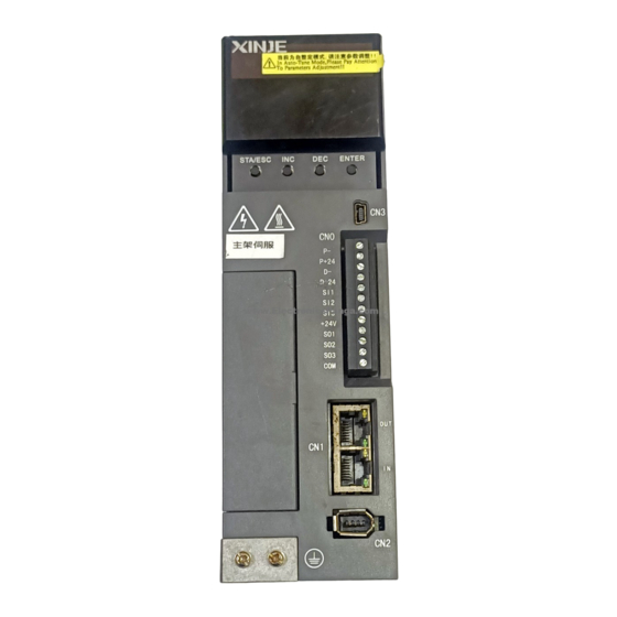
1.Servo system model 1-1.Servo driver 1-1-1.Part description Signal terminal Power supply Motor wiring RJ45 port Encoder port 1-1-2. Model name DS5□ – 2 0P7 – PTA Series name Configuration type: DS5C: EtherCAT P-input command: pulse type Encoder type: Motor capacity T-communication encoder Voltage level 0P1: 0.1KW... -
Page 12: Performance
1-1-3. Performance Servo unit DS5C series 220V Suitable encoder Standard: 17bit/ 23bit encoder DS5C-2□P□-PTA: single phase AC200~240V, 50/60Hz 【below 1.5KW(except 1.5KW) can use single phase AC200~240V 50/60Hz; 1.5KW and up please use single phase or Input power supply 3-phase AC200~240V 50/60Hz. (for single phase power supply, please connect L1, L3, otherwise it will affect the power-off memory)】... -
Page 13: 1-2.Servo Motor
1-2.Servo motor 1-2-1.Part description Encoder part Frame Flange Output (transmission) shaft... -
Page 14: Model Name
1-2-2. Model name MS5S – 80 ST E – C S 02430 B Z - 2 0P7 – S01 Name inertia Name Design no. standard MS5S Low inertia MS5G Middle inertia Rated power MS5H High inertia Name (KW) Name Base no. 60 base 0.75 80 base... -
Page 15: Model Name
P is suitable for the motor with the suffix S01, W is applicable to motor with the suffix S02. CB series brake cable is suitable for the motor with the suffix S01, CMB series brake cable is suitable for the motor with the suffix S02. 1-3-2. -
Page 16: 1-4.Other Accessories
Power supply cable model CM –P 07 – M - 02 Length: 02: 2M; 03: 3M M: magnetic type Cable diameter: 07:0.7mm² ;15:1.5mm² ; 25:2.5mm² ;60:6mm² ;100:10mm² P:Straight amp plug; W:Special low power 6- core aviation plug CM:Normal cable CMB: Brake cable CMT:High flexible cable ... -
Page 17: Product Installation
Servo driver model Regenerative resistor connection terminals for internal regenerative resistor: short P+ and D, disconnect P+ and C, P0-24=0. DS5C-2□P□-PTA for external regenerative resistor: connect resistor between P+ and C, disconnect P+ and D, P0-24=1, P0-25=power value, P0-26=resistor value. The below table is external regenerative resistor specifications for each motor. -
Page 18: 2-1-2.Environment Conditions
No vibration location 2-1-2.Environment conditions Item Description Using temperature 0℃~40℃ (not freeze) Using humidity -20%~90%RH (no condensation) Storage -20℃~60℃ temperature Storage humidity -20%~90%RH (no condensation) Protection level IP65 2-1-3.Installation standard Be sure to comply with the installation standard in the control panel shown below, which is applicable for installing multiple servo drives side-by-side in the control panel (hereinafter called "side-by-side installation"... - Page 19 Servo drive direction When installing, make the front of the servo drive (the actual installation surface of the operator) facing the operator and make it vertical to the wall. For the drive with regenerated resistance at the bottom, please pay attention to the heat dissipation of the mounting surface to avoid overheating of the drive and causing fire.
-
Page 20: 2-2.Servo Motor Installation
Ambient Temperature: 0~50 ℃ Humidity: 90%RH or less Vibration: 4.9m/s Condensation and Freezing: None Ambient Temperature for Long-term Reliability: 50° C maximum 2-2.Servo motor installation MS series servo motors can be installed either horizontally or vertically. The service life of the servo motor can be shortened or unexpected problems might occur if it is installed incorrectly or in an inappropriate location. -
Page 21: Environment Conditions
please do not use the motor in a closed environment. Closed environment will lead to motor temperature, shorten service life 2-2-2. Environment conditions When used in places with water or oil, the protective effect can be achieved through the treatment of the motor. - Page 22 ◆ The installation process is not allowed to impact the shaft extension, otherwise the internal encoder will be broken. ◆ When a pulley is mounted on a servo motor shaft with a keyway, screw holes are used at the end of the shaft. To install the pulley, first insert the double-headed nail into the screw hole of the shaft, use the washer on the surface of the coupling end and gradually lock the nut Encoder notes...
- Page 23 ◆ When installing the servo motor, make it meet the centering precision requirements as shown below. If the centering is not sufficient, vibration may occur, and sometimes the bearing and encoder may be damaged. When installing the shaft coupler, please do not directly impact the motor shaft, otherwise it will damage the encoder installed on the load reverse side of shaft end.
- Page 24 level in good condition. When installing the servo motor vertically up, please pay attention not to grease the lip of the oil seal. Do not "bend" the wire or apply "tension" to it. Especially, the core wire The stress state of the cable of the signal wire is 0.2mm or 0.3mm, very thin.
-
Page 25: 2-3.Servo Motor Dimension
2-3.Servo motor dimension 40 series motor dimension Unit: mm █ Body length Inertia level Motor model Normal With brake Low inertia 129.5± 1 MS5S-40ST-CS0030□□-20P1-S01/S02 99± 1.5... - Page 26 60 series motor dimension Unit: mm Body length Inertia level Motor model Normal With brake MS5S-60ST-CS00630□□-20P2-SO1/S02 79± 1 114± 1 Small inertia 99± 1 134± 1 MS5S-60ST-CS01330□□-20P4-S01/S02...
- Page 27 Body length Inertia level Motor model Normal With brake 146± 1 MS5H-60ST-CS01330□□-20P4-SO1/S02 111± 1 Large inertia MS5H-60ST-CS00630□□-20P2-SO1/S02 91± 1 126± 1 80 series motor dimension Unit: mm Body length Inertia level Motor model With Normal brake Small inertia MS5S-80ST-CS02430□□-20P7-SO1/S02 107±...
- Page 28 Body length Inertia level Motor model Normal With brake MS5H-80ST-CS02430□□-20P7-SO1/S02 119± 1 156± 1 Large inertia MS5H-80ST-CS03230□□-21P0-SO1/S02 140± 1 177± 1...
-
Page 29: 2-4.Servo Drive Dimension
2-4.Servo drive dimension Unit: mm DS5C-20P1/2/4-PTA 45.0 175.1 33.8 Ø5.5 Ø5.5... - Page 30 DS5C-20P7-PTA 60.0 181.3 Ø5.5 48.8 Ø5.5...
-
Page 31: Servo Drive And Motor Wiring
3.Servo drive and motor wiring 3-1. Main circuit terminals DS5C-20P1/2/4/7-PTA Terminal Function Explanation Power supply input of Single phase AC200~240V, 50/60Hz main circuit Vacant terminal ● Connect the motor U, V, W (Note: the ground line is on the Motor terminals cooling fin, please check it before power on!) -
Page 32: Control Terminals
3-2. Control terminals The serial numbers of the following connectors are in the order of viewing the welding side. CN0 terminals Name Explanation Name Explanation Pulse input PUL- Input 3 P+24V Open collector input +24V Input +24V Direction input DIR- Output 1 D+24V Open collector input... - Page 33 CN1 terminals Name Name Outlet TAX A+ TAX B+ TAX A- TAX B- RX A+ RX B+ Inlet RX A- RX B- Note: The servo bus function needs to be equipped with the bus module, which is inserted into the driver CN1 port for the purpose of extending the bus function.
-
Page 34: Operation Before Using Servo System
4. Operation before using servo system 4-1.Operate panel Button Function power Press: Status switch, status return STA/ESC Press: Increase the value; Press and hold: Increase the value continuously Press: Decrease the value; Press STA/ESC ENTER and hold: Decrease the value continuously Press: Shift the editing digit;... -
Page 35: 4-1-1.Group P Parameters
STA/ESC Monitor Alarm Auxiliary Parameter State F0-00 E-XXX U0-00 P0-00 Idle Function Speed Code P1-00 U1-00 Alarm Control code Reset U2-00 F1-00 P7-00 Communication Power on time Monitor Function UX-XX: The first X means group No., the last two X means the member No. -
Page 36: 4-1-2.Group U Parameters
4-1-2.Group U parameters U0-21 input signal status U0-21 input signal 1 distribution Segment Segment Explanation Explanation code code /P-CON proportion action /S-ON servo enable signal command /P-OT forward /N-OT reverse run prohibited prohibited /P-CL forward side external torque /ALM-RST alarm reset limit /N-CL reverse side external /SPD-D internal set speed selection... - Page 37 Note: read the status through communication, the binary value from right to left are related to /S-ON, /P-CON. 0 means no input, 1 means has input. For example: 0x0001 means /S-ON has input, 0x0201 means /S-ON and /SPD-B has input. U0-22 input signal status U0-22 input signal 2 distribution Segment...
- Page 38 0x0001 means /C-SEL has input, 0x0041 means /C-SEL and /I-SEL has input. Note: “—“ is reserved bit, it is always 0. U0-23 output signal status U0-23 output signal 1 distribution Segment Segment Explanation Explanation code code Positioning complete maintain Positioning end (/COIN) (/COIN_HD) Same speed detection (/V-CMP) Rotate detection (/TGON)
- Page 39 U0-24 output signal status U0-24 output signal 2 distribution Segment code Explanation Segment code Explanation — Alarm (/ALM) — — Speed reach (/V-RDY) Self-defined output 1 — Self-defined output 2 — — Note: read the status through communication, the binary value from right to left are related to /ALM, “-“.
-
Page 40: Fx-Xx Auxiliary Function
4-1-3. FX-XX auxiliary function F0-XX Function No. Description F0-00 Clean the alarm F0-01 Back to out of factory settings F0-02 Clean the offset Clean the alarm (F0-00) Set F0-00=1 to reset the alarm. When the alarm occurred, please find out the alarm reasons then clean the alarm. - Page 41 1. Jog run (F1-00) Make sure that the motor shaft is not connected to the machine before jogging! Press ENTER Keep Press ENTER Reverse F1-00 Forward When the servo is in jog run mode, gain and other parameters will join the process. Please adjust the parameters according to the jog run status.
- Page 42 Motor reverse run Keep Press ENTER Press ENTER F1-01 Motor forward run STA/ESC STA/ESC F1-01 3. Current sampling zero calibration (F1-02) After the servo drive updated to latest software version, or the motor does not revolve smoothly for long time, the current offset auto-adjustment is recommended. Keep press ENTER Press ENTER donE...
-
Page 43: Panel Key Operation
Set P0-03 to 2 F1-05 = 0: cancel the enable, back to bb state. F1-05 = 1: forced enable, servo is in RUN state. Note: forced enable will be ineffective after power on again. 5. Absolute encoder clear number of turns First power off the servo drive, then clear the absolute encoder number of turns. -
Page 44: Change Motor Code
On servo ENTER ENTER Driver label XINJE SERVO DRIVER DS5C-20P7-PTA Driver model Operation notes WARNING CAUTION Input power supply AC INPUT:1PH/3PH 200-240V 50/60Hz 3.5A specification Output power AC OUTPUT:3PH 0-200V 3.5A 0.75KW supply specification Production no. 12052013 WUXI XINJE ELECTRIC CO.,LTD... -
Page 45: Gain Adjustment
5. Gain adjustment The new generation DS5 series servo has rigidity self-adaption, auto-tuning and manual adjustment modes, without complicated parameter adjustment process, which greatly saves the gain adjustment time. Self-adaption function: self-adaption function means that no matter the type of machinery and the fluctuation of load, it can get stable response through automatic adjustment. -
Page 46: Self-Adaption Mode Selection Switch Parameter
5-1-1. Self-adaption mode selection switch parameter Inertia mode Self-adaption Parameter notes selection switch default parameters P2-05=400 Adaptive small inertia mode speed loop gain P2-11=100 Adaptive small inertia mode position loop gain P2-10=500 Adaptive small inertia mode speed loop integral P2-03.3=0 P2-07=0 Adaptive small inertia mode inertia Small inertia mode... - Page 47 observer gain P6-12=50 Adaptive large inertia mode stable max inertia ratio P2-19=70 Adaptive large inertia mode control bandwidth Note: (1) P2-19 default value is different for different power drive. (2) P2-05 default value is 200 for the drive above 1.5kw. Parameter Default Range...
-
Page 48: Recommended Inertia Ratio Under Default Parameters
responsiveness, as an auxiliary parameter. 5-1-2. Recommended inertia ratio under default parameters Motor Recommended load inertia ratio Recommended load inertia flange in small inertia mode ratio in large inertia mode Below 20 times 60 times ~ 80 times Below 20 times 60 times ~ 80 times Below 20 times 60 times ~ 80 times... -
Page 49: 5-2.Auto-Tuning
P2-10=1000 5-2.Auto-tuning Auto-tuning parameter setting is based on the current institution, the parameters after auto-tuning is not applicable to empty shaft and other types of load, the auto-tuning is divided into no instruction auto-tuning and auto-tuning with instruction, it needs the servo PC software to adjust, detailed usage please refer to PC software manual. -
Page 50: 5-3.Manual Adjustment
5-3.Manual adjustment Manual adjustment needs to set load inertia first, then turn off the self-adaption function to use. Servo firmware version 3640 and later supports this function. 5-3-1.Manual adjustment steps 1. Set the load inertia ratio P0-07 (Estimation of inertia by upper computer or known load inertia). -
Page 51: 5-3-2.Manual Adjustment Parameter And Function
5-3-2.Manual adjustment parameter and function Parameter Name Explanation P0-07 Load inertia The ratio of load and rotor inertia, the value can be deduced ratio by the upper device inertia recognition P1-00 Speed loop gain In the absence of noise and vibration, increasing this parameter can speed up the positioning time and bring better speed stability and follow-up. -
Page 52: 5-4.Vibration Suppression
5-4.Vibration suppression When the excitation frequency of the mechanical system is close to the natural frequency of a certain order of the system, the system amplitude increases significantly, which will cause vibration and noise. Generally, the screw equipment with small load inertia can achieve better results by auto-tuning directly with the upper computer. - Page 53 Notch depth frequency (1) Open the Xinje servo software, click mechanical properies (2) Click measure, it will show below window (3) click execute, wait for data reading to complete (4) click amplitude and phase, set the filter width according to the waveform sharpness...
-
Page 55: Ethercat Communication Specification
(6) open vibration suppression switch, set the vibration frequency (7) if there is still vibration after setting notch frequency, please adjust P2-35. Refer to below table for detailed parameters: Parameter Name Explanation P2-00.0 Disturbance observer switch 0: Close 1: Open P2-41 Disturbance observer gain Default 91, Generally changed to 85... -
Page 56: Canopen Operation Mode
FMMU0:Periodic Data Output Zone FMMU(Bus Memory FMMU1:Periodic Data Output Zone Management Unit) FMMU2:Mailbox status zone Application Layer CoE:CANopen over EtherCAT Protocol Synchronization mode DC Synchronization mode(SYNC0) SDO:Aperiodic data objects Communication object PDO:Periodic Data Objects LED light(the indicator EtherCAT ERR(ER) × 1 lamp is located on the EtherCAT Link / Activity(L / A) ×... -
Page 57: 7-1-2.Operation Steps
7-1-2.Operation steps 1. 【Mode of operations:6060h】set to homing mode)(0x06). 2. set 【Homing method:6098h】, the range is 1 to 35. (support method 1, 2, 3, 4, 5, 6, 33, 34, 35, 37) 3. set【Homing speeds:6099h Sub-1】, define the speed when searching for origin switches (unit: command unit/s) 4. -
Page 58: 7-2.Cyclic Synchronous Position Mode
7-2.Cyclic Synchronous Position Mode 7-2-1.Summary The host computer plans the path in CSP mode and sends the PDO in a specified period. When transmitting each PDO, the data of target position and control word will be transmitted to the driver at the same time. 7-2-2.CSP mode 7-2-3.Operation steps 1. -
Page 59: 7-2-4.Related Object Table
Use 6040h Sub-0 to set control word. 7-2-4.Related object table Index Name Units Access 6040h Control word 6072h Max torque 0.1% 607Ah Target Position Command unit Soft Position Limit 607Dh Number of entries Position range limit 607Bh HighestSub-Index numbers 60C5h Max acceleration Command unit /s... -
Page 60: 7-3.Cyclic Synchronous Velocity Mode
unit /s 6076h Motor rated torque mN· m 6077h Torque actual value 0.1% Following error actual value Command 60F4h unit Control effort ( Represents the output of internal Command 60FAh instruction speed, position loop output) unit Position deamnd internal value(represents internal Command 60FCh command position)... -
Page 61: 7-3-2.The Function Of Csv Mode
7-3-2.The function of CSV mode 7-3-3.Operation steps 1. set【Mode of operations:6060h】 to Cyclic Synchronous Velocity Mode)(0x09). 2. set 【 Interpolation time period:60C2h】 , the settings should be same to the period of SYNC0. 60C2h Sub-1 can set Interpolation time units, the range is 1ms~20ms. ... -
Page 62: 7-3-4.Related Object Table
7-3-4.Related object table Index Name Units Access 6040h Control word 6072h Max torque 0.1% 60B1h Velocity offset Command unit/s 60FFh Target velocity Command unit/s Detection classes related to csv control mode Index Name Units Access 6041h Statusword 6063h Position actual internal value Pulse 6064h Position actual value... -
Page 63: 7-4-2.The Function Of Cst Mode
7-4-2.The function of CST mode 7-4-3.Operation steps 1. set【Mode of operations:6060h】to Cyclic Synchronous Velocity Mode(0x09) 2. set 【 Interpolation time period:60C2h】 , the settings should be same to the period of SYNC0 60C2h Sub-1 can set the Interpolation time units, the range is 1ms~20ms. ... -
Page 64: 7-4-4.Related Object Table
7-4-4.Related object table Index Name Units Access 6040h Control word 6071h Target Torque 0.1% 6072h Max Torque 0.1% 60B2h Torque offset 0.1% Detection classes related to cst control mode Index Name Units Access 6041h Status word 6063h Position actual internal value Pulse 6064h Position actual value... -
Page 65: Mode Common Function
8.Mode common function 8-1.Touch Probe Function 8-1-1.Summary The probe function can be triggered by the SI terminal of CN0 or encoder, and the feedback position can be fixed to the rising or falling edge by the P-(SI5)/D-(SI6) input terminal of CN0. - Page 66 60B8h. value note switch off Touch probe 1 stop/execute Touch probe1 enable Touch probe 1 Trigger first event Touch probe1 mode selection Continuous Trigger with Touch probe1 input Touch probe1 triggering selection Trigger with zero impulse signal of position (external input/Z phase) encoder Reserved Not used...
- Page 67 Reserved Not used switch off sampling at positive edge of touch Touch probe2 rising edge probe2 selection enable sampling at positive edge of touch probe2 switch off sampling at negative edge of touch probe2 Touch probe2 falling edge selection enable sampling at negative edge of touch probe2 14-15 reserved...
-
Page 68: 8-2.Position Information
Touch probe2 no positive edge value stored Rising edge probe incomplete state Touch probe2 positive edge value stored Rising edge probe completion state Touch probe2 no negative edge value stored Falling edge probe incomplete state Touch probe2negative edge value stored Falling edge probe... -
Page 69: Initialization Of Absolute Encoder
【Gear ratio:6091h】 Motor revolutions(6091h-01h) Electronic gear ratio= Shaft revolutions(6091h-02h) 【Position encoder resolution:608Fh】 【Feed constant:6092h】 The default value of motor resolution and encoder frequency division ratio is 1. 8-2-2. Initialization of absolute encoder When absolute encoder is used in position control mode and multi-loop mode, it no needs to return to the origin. -
Page 70: 8-3.Interpolation Time Period
8-3.Interpolation time period 【Interpolation time period:60C2h】 is set automatically according to the communication cycle, please do not change. Communication period 60C2h-01h 60C2h-02h 250us 500us Index Sub-Index Name Units Access Interpolation time period Highest Sub-Index supported 60C2h Interpolation time period value Interpolation time index 9. -
Page 71: 9-1-2.Driver Profile Zone
9-1-2.Driver Profile zone Index Name Data type Access 603Fh Error Code UNSIGNED16 6040h Controlword UNSIGNED16 6041h Statusword UNSIGNED16 605Bh Shutdown option code INTEGER16 605Eh Fault reaction option INTEGER16 code 6060h Modes of operation INTEGER8 6061h Modes operation INTEGER8 display 6062h Position demand value INTEGER32 [PUU]... - Page 72 6074h Torque demand value INTEGER16 6075h Motor rated current UNSIGNED32 6076h Motor rated torque UNSIGNED32 6077h Torque actual value UNSIGNED16 6078h Current actual value INTEGER16 607Ah Target position INTEGER32 607Ch Home Offset INTEGER32 607Dh ARRAY Software position limit INTEGER32 607Eh Polarity UNSIGNED8 607Fh...
- Page 73 60C6h Max deceleration UNSIGNED32 60F2h Positioning option code UNSIGNED16 60F4h Following error actual INTEGER32 value 60FCh Position demand value INTEGER32 60FDh Digital inputs UNSIGNED32 60FFh Target velocity INTEGER32 6502h Supported drive modes UNSIGNED32 Xinje custom area 2000h~281Ah Parameter Mapping INTEGER16/32...
-
Page 74: 9-2.Driver Parameters
9-2.Driver parameters 9-2-1.Group P parameters Modification and Effective Time: ○ Represents Servo OFF Modification, effective immediately; √ means that it may be changed at any time and shall take effect immediately. ● represents need to re-energize to take effect after the change; Adding “n.”... - Page 75 1:IO/SON Input Signal Software enabled (panel/Modbus) panel F1-05 writes 1; Modbus writes 1 to 0x2105 register. Write cancel enablement 3: Bus Enablation ● Rigidity level 1-31 ● Selection of rotation direction ○ Forward direction of input pulse 6、7 command ○ 0:CW/CCW 6、7 1:AB...
- Page 76 mand unit ○ Discharge resistance type 0: built in 1: external √ Discharge Resistance power Related 0~655 Ω √ driver Discharge Resistance value 0~655 power ○ Servo OFF Stop Mode 0、2 0: Inertial operation stops and remains in inertial operation state after stopping.
- Page 77 after stopping. 2: The deceleration operation stops, and the inertia operation state is maintained after the stop. ○ Stopping overtime time 0.1m 2000 0~655 ● Motor code 0~655 ○ Fan power on 0:Turn on the fan with temperature greater than 45 degrees and turn off the fan with temperature less than 42 degrees (hysteresis 3 degrees Celsius)
- Page 78 Name Unit Default Range Effec Suitabl tive e mode √ The gain of speed loop (fit 10~20000 for auto-tuning mode) √ speed loop integral time(fit 0.1ms 3300 15~51200 for auto-tuning mode) √ The gain of position loop 10~20000 (fit for auto-tuning mode) √...
- Page 79 ● 00.2 Dead zone compensation 0000-000f switch ● 03.3 Self-adaptive mode switch ● Speed loop gain in adaptive 1~65535 mode ● Load inertia ratio in adaptive 0~10000 mode ● Speed observer gain 1~10000 ● Stable max inertia ratio in 1~10000 adaptive mode ●...
- Page 80 P3: speed control Name Unit Default Range Effec Suitable value tive mode — ○ V-REF Function 1、 2、 4、 Allocation 0:V-REF is input as speed instruction. 1:V-REF will be used as the input reference value of the external speed limit. The actual speed limit depends on the external analog speed limit.
- Page 81 command is 0. When the speed below P3-13, switch to position mode and the servo locked in this position 1: ZCLAMP input signal is ON, forced set speed command to 0 2: ZCLAMP input signal is ON, speed below P3-13 switch to position mode and the servo locked in this position...
- Page 82 higher than P3-13, motor work again. ○ Zero speed clamp speed 0~300 3、4 ○ Forward speed Related to 30~10000 command limit motor ○ Reverse speed Related to 30~10000 command limit motor √ Internal forward speed Related to 1、2 limit in torque control motor 30~10000 mode...
- Page 83 P3-28/P3-29, minimum value is valid, as a necessary condition limiting input external torque. 2: Torque Feedforward √ Internal forward torque 0~300 limit √ Internal reverse torque 0~300 limit √ External forward torque 0~300 2、 3、 4、 6、7 limit √ External reverse torque 0~300 2、...
- Page 84 ○ Pass Z phase signal times 5、6 .xxx□ after leaving the limit switch ○ Find origin function 5、6 xx□x 0: OFF 1: ON ○ Hit proximity switch 1rpm 0~50000 5、6 speed ○ Leaving proximity switch 1rpm 0~50000 5、6 speed ○ Internal position mode n.0000 ○...
- Page 85 P5: signal setting Name Unit Range Effec Suita ault tive mode ○ Positioning finished width /COIN Comman 0~65535 d unit ○ Positioning finished checking mode 0: offset absolute value below P5-00, output COIN signal 1: offset below P5-00 after command finished, output COIN signal 2: command finished, motor speed below P5-03 and offset absolute...
- Page 86 ○ 0~10000 Brake command output speed ○ 0~65535 Brake command waiting time ○ 0~FFFF User-defined output trigger condition ○ Set a value that compares with the Related -9999~99 trigger condition of custom output 1 trigger condition ○ 0: P5-10≥P5-11, output SOx 1: P5-10<P5-11, output SOx 2: P5-10 absolute value≥...
- Page 87 ○ custom output 2 hysteresis Related 0~65535 trigger condition ○ IO filter time 0~10000 √ Z phase signal pulse width 2~20 √ - ※1 /S-ON servo signal 0000: signal is always invalid 0001: input positive signal from SI1 0002: input positive signal from SI2 0003: input positive signal from SI3 0004: input positive signal from SI4 0010: signal is always valid...
- Page 88 √ - ※1 /N-CL reverse side external torque limit ditto √ - ※1 /SPD-D internal speed direction 1、 2、 3、4 choice ditto √ - ※1 /SPD-A internal setting speed choice 3、6 ditto √ - ※1 /SPD-B internal setting speed choice 3、6 ditto √...
- Page 89 0011: output negative signal from 0012: output negative signal from 0013: output negative signal from √ - ※2 /COIN positioning finished ditto √ - ※2 /V-CMP same speed checking 3、 4、 ditto √ - ※2 /TGON rotation checking ditto √ -...
- Page 90 ○ - ※2 /Custom Output 1 Output Port Settings ○ - ※2 /Custom Output 2 Output Port Settings √ - ※1 PREFA segment 1 internal position √ - ※1 PREFB segment 2 internal position √ - ※1 PREFC segment 3 internal position ○...
- Page 91 P7: communication parameters (not support RS485 communication) Name Unit Default Range Effect Suita value mode ○ RS485 station no. 1~255 n.xx□□ ○ RS485 Baud 00~10 0A: 192000 00:300 0B: 256000 param rate 01:600 0C: 288000 eter 02:1200 0D: 384000 03:2400 0E:...
- Page 92 sampling time — ○ Xnet slave station 1~500 data — ○ Xnet slave station 1~256 numbers ○ Communication time 1~500 overtime retry times ○ Fieldbus command 3000 1~65535 update period — ○ RS232 station no. 1~255 — ○ RS232 parameter 2206 Parameter same...
-
Page 93: 9-2-2.Group F Parameters
Table 1 Input signal allocation input terminal Servo model Setting range P5-20~P5-36 n.0000~n.0003 DS5C series P5-57~P5-59 n.0010~n.0013 Table 2 Output Signal Allocation output terminal Servo model Setting range n.0000~n.0003 P5-37~P5-53 DS5C series n.0010~n.0013 9-2-2.Group F parameters Code Explanation F0-00 Clean the alarm... - Page 94 U0-03 Mechanical angle 1° U0-04 Electric angle 1° U0-05 Bus voltage U0-06 IPM temperature 0.1℃ U0-07 Torque feedback % rated (0000~9999)*1 U0-08 Pulse offset value Command pulse (0000~9999)*10000 U0-09 Encoder feedback U0-10 0000~9999 encoder pulse value (0000~9999)*1 U0-12 Pulse value of input Command pulse (0000~9999)*10000 command...
- Page 95 U0-44 Average thermal power U0-49 Position feedforward 1 command unit U0-50 Speed feedforward U0-51 Torque feedforward % rated U0-52 Instantaneous bus capacitor power U0-53 Average bus capacitor power U0-55 Instantaneous regenerative braking discharge power U0-56 Average regenerative braking discharge power Read address U0-57...
- Page 96 U1-09 Speed value when alarming The alarm occurred time second (low 16 bits), count from the U1-10 first time power on The alarm occurred time second (high 16 bits), count from the U1-11 first time power on U1-12 Run error times, count from power on this time U1-13 Warning times, count from power on this time U1-14...
- Page 97 U2-05 Out of factory date: year U2-06 Out of factory date: month U2-07 Out of factory date: day U2-08 Firmware version U2-09 Total run time (from the first time power on) Hour U2-10 Total run time (from the first time power on) Minute U2-11 Total run time (from the first time power on)
-
Page 98: Appendix
Appendix Appendix 1 motor specification table Voltage level 220V Motor model MS 5S-40ST- 5S-60ST 5H-60ST 5S-60ST- CS00630 CS00630 CS01330 CS00330 -20P1-S01/S02 -20P2-S01/S02 -20P2-S01/S02 20P4-S01/S02 Motor code (no brake/with 5003/5803 5803/58C3 5004/5804 5022/5822 brake ) Encoder bit numbers Polar logarithm Rated speed [rpm] 3000 3000 3000... - Page 99 Rated output power Protection level IP65 Motor insulation Class F ( 155 ℃) level Ambient - 15 ℃~+ 40 ℃ temperature Ambient humidity Relative humidity < 90% (no condensation) Voltage level 220V Motor model MS 5H-60ST 5S-80ST 5H-80ST CS02430 CS02430 CS01330 -20P4-S01/S02 -20P7-S01/S02...
-
Page 100: Appendix 2. List Of Servo Drive And Motor Matching
Phase inductance 2810 3300 3300 [mH] Rotor inertia 1650 kg.m Back EMF constant [V/krpm] Rated output power Protection level IP65 Motor insulation Class F ( 155 ℃) level Ambient - 15 ℃~+ 40 ℃ temperature Ambient humidity Relative humidity < 90% (no condensation) Appendix 2. - Page 101 MS5S-60ST-C00630B-20P2-S01/S02 5003 DS5C-20P2-PTA Single-phase 220V MS5S-60ST-C00630BZ-20P2-S01/S02 5803 DS5C-20P2-PTA Single-phase 220V MS5H-60ST-C00630B-20P2-S01/S02 50C3 DS5C-20P2-PTA Single-phase 220V MS5H-60ST-C00630BZ-20P2-S01/S02 58C3 DS5C-20P2-PTA Single-phase 220V MS5S-40ST-CS00330B-20P1-S01/S02 5022 DS5C-20P1-PTA Single-phase 220V MS5S-40ST-CS00330BZ-20P1-S01/S02 5822 DS5C-20P1-PTA Single-phase 220V Note: The motor is divided into large inertia, small inertia and brake motor, and the motor codes are different from each other.
-
Page 102: Appendix 3. Alarm List
Appendix 3. Alarm list Code Contents Reason Solution Hardware The hardware version is version Contact us E-010 error match System loading Contact us The program damaged E-012 error FPGA loading 1. program damaged Contact us E-013 error 2. hardware damaged 1. - Page 103 value and set again range range range TREF or VREF Parameter Parameter 1. P0-01=4, P3-00=1 function setting conflict conflict will alarm conflict User-defined Sampling output trigger Sampling channel Check setting channel or data channel setting setting parameter monitor channel error error setting error 1.for single phase 220V,...
- Page 104 2. not connect 2. connect regenerative 390 alarm, regenerative resistor 380V: U0-05 ≥ (220V: resistor check U0-05 ≥ 780V alarm) regenerative regenerative resistor 390 alarm, damaged matched power 380V: resistor too large U0-05 ≥ 780V alarm) undervolta undervoltage(22 ge(220V: 1. Power grid check grid U0-05 ≤...
- Page 105 decrease load good ventilation, decrease environment temperature 3. check if the fan works when servo enabled, module temperature U0-06≥45℃, fan will work. 1. long time running 1. decrease the Motor with large load load temperature too E-061 environment good high temperature too high ventilation Environment...
- Page 106 operated on an empty shaft to eliminate load problem. 1. check if there is external force make the motor 1. motor speed too fast over speed motor 2. check UVW E-080 Over speed connection error wiring 3. parameters error 3. actual speed larger than P3-21/P3-22 will alarm...
- Page 107 short circuit circuit when UVW wiring self-checking 2. change drive 2、 load blocked 3. change motor 4. suggest to run without load, to troubleshoot load problem Current sensor Check Current sensor damaged or external ground wiring or E-120 error interference too large contact us U phase current Current...
- Page 108 properly. Re-energize after eliminating errors Check power Motor U/V/W phase break line U/V/W E-150 phase break during self-inspection connection normal 1. Change larger power motor Motor output Motor output power Check E-160 power overload over the rated power motor shaft wiring 1、...
- Page 109 motor output torque torque setting is larger than P3-28, suitable P3-29, it will alarm 2. check external mechanical structure installation 1. check if the 11KW and 15KW large machine power motor encoder Motor blocked. cover installed E-166 temperature too 2. if the motor is thermistor, will alarm high running...
- Page 110 encoder contactor not good power, check communication encoder wiring, error use multi-meter test the connection encoder wire together with the strong power supply cable, recived encoder data install filter at error, and error time servo drive over encoder error time power supply register P0-56 value...
- Page 111 lose and servo will alarm, set F0-00=1 to clear this alarm Unplugging the Absolute Encoder problem, or encoder cable encoder data power supply is not E-223 without battery visit alarm stable will alarm Unplugging the Absolute Large change encoder cable encoder E-224 encoder data...
- Page 112 encounter forward over range signal 1. decrease the inertia 1. inertia too big motor with 2. stop overtime too Control stop brake short E-262 over time 2. increase stop 3. brake torque too overtime P0-30 small 3. increase brake torque P3-32 Reduce the gain of servo position loop or speed...
-
Page 113: Appendix 4. Modbus Address List
Appendix 4. Modbus address list Parameter address Parameter Modbus address Parameter Modbus address Decimal Decimal P0-00 0x0000 P0-17 0x0011 P0-01 0x0001 P0-18 0x0012 P0-02 0x0002 P0-19 0x0013 P0-03 0x0003 P0-20 0x0014 P0-04 0x0004 P0-21 0x0015 P0-05 0x0005 P0-22 0x0016 P0-06 0x0006 P0-23... - Page 114 P1-02 0x0102 P1-17 0x0111 P1-03 0x0103 P1-18 0x0112 P1-04 0x0104 P1-19 0x0113 P1-05 0x0105 P1-20 0x0114 P1-06 0x0106 P1-21 0x0115 P1-07 0x0107 P1-22 0x0116 P1-08 0x0108 P1-23 0x0117 P1-09 0x0109 P1-24 0x0118 P1-10 0x010A P1-25 0x0119 P1-11 0x010B P1-26 0x011A P1-12 0x010C P1-27...
- Page 115 P3-06 0x0306 P3-25 0x0319 P3-07 0x0307 P3-26 0x031A P3-08 0x0308 P3-27 0x031B P3-09 0x0309 P3-28 0x031C P3-10 0x030A P3-29 0x031D P3-11 0x030B P3-30 0x031E P3-12 0x030C P3-31 0x031F P3-13 0x030D P3-32 0x0320 P3-14 0x030E P3-33 0x0321 P3-15 0x030F P3-34 0x0322 P3-16 0x0310 P3-35...
- Page 116 P5-06 0x0506 1286 P5-33 0x0521 1313 P5-07 0x0507 1287 P5-34 0x0522 1314 P5-08 0x0508 1288 P5-35 0x0523 1315 P5-09 0x0509 1289 P5-36 0x0524 1316 P5-10 0x050A 1290 P5-37 0x0525 1317 P5-11 0x050B 1291 P5-38 0x0526 1318 P5-12 0x050C 1292 P5-39 0x0527 1319 P5-13...
- Page 117 Parameter Modbus address Parameter Modbus address Decimal Decimal P7-00 0x0700 1792 P7-10 0x070A 1802 P7-01 0x0701 1793 Monitor status group U Parameter Modbus address Parameter Modbus address Decimal Decimal U0-00 0x1000 4096 U0-28 0x101C 4124 U0-01 0x1001 4097 U0-29 0x101D 4125 U0-02...
- Page 118 U0-20 0x1014 4116 U0-48 0x1030 4144 U0-21 0x1015 4117 U0-49 0x1031 4145 U0-22 0x1016 4118 U0-50 0x1032 4146 U0-23 0x1017 4119 U0-51 0x1033 4147 U0-24 0x1018 4120 U0-52 0x1034 4148 U0-25 0x1019 4121 U0-53 0x1035 4149 U0-26 0x101A 4122 U0-57 0x1039 4153 U0-27...
- Page 119 U1-16 0x1110 4368 U2-16 0x1210 4624 U1-17 0x1111 4369 U2-17 0x1211 4625 U1-18 0x1112 4370 U2-18 0x1212 4626 U1-19 0x1113 4371 U2-19 0x1213 4627 U1-20 0x1114 4372 U2-20 0x1214 4628 U1-21 0x1115 4373 U1-22 0x1116 4374 U1-23 0x1117 4375 U1-24 0x1118 4376 U1-25...
- Page 121 WUXI XINJE ELECTRIC CO., LTD. 4th Floor Building 7,Originality Industry park,LiyuanDevelopmentZone,Wuxi City, Jiangsu Province 214072 Tel: 400-885-0136 Fax: 86-510-85111290...
Need help?
Do you have a question about the DS5C Series and is the answer not in the manual?
Questions and answers