Table of Contents
Advertisement
Visit our website at
www.MillerWelds.com
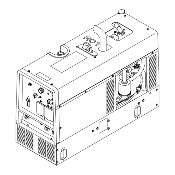
Trailblazer 301 D
OM-4410
July 2005
Processes
MIG (GMAW) Welding
Flux Cored (FCAW)
Stick (SMAW) Welding
TIG (GTAW) Welding
Air Plasma Cutting and Gouging
R
with Spectrum
Unit
Air Carbon Arc (CAC-A) Cutting
and Gouging
Description
Engine Driven Welding Generator
R
File: Engine Drive
206 933P
Advertisement
Table of Contents
Troubleshooting

Related Manuals for Miller Trailblazer 301 D


Summary of Contents for Miller Trailblazer 301 D
- Page 1 Flux Cored (FCAW) Stick (SMAW) Welding TIG (GTAW) Welding Air Plasma Cutting and Gouging with Spectrum Unit Air Carbon Arc (CAC-A) Cutting and Gouging Description Engine Driven Welding Generator Trailblazer 301 D File: Engine Drive Visit our website at www.MillerWelds.com...
- Page 2 We know you don’t have time to do it any other way. That’s why when Niels Miller first started building arc welders in 1929, he made sure his products offered long-lasting value and superior quality.
-
Page 3: Table Of Contents
TABLE OF CONTENTS SECTION 1 − SAFETY PRECAUTIONS − READ BEFORE USING ........1-1. - Page 4 TABLE OF CONTENTS SECTION 8 − MAINTENANCE AND TROUBLESHOOTING ........8-1.
-
Page 5: Section 1 − Safety Precautions − Read Before Using
SECTION 1 − SAFETY PRECAUTIONS − READ BEFORE USING rom _nd_8/03 Y Warning: Protect yourself and others from injury — read and follow these precautions. 1-1. Symbol Usage Means Warning! Watch Out! There are possible hazards with this procedure! The possible hazards are shown in the adjoining symbols. -
Page 6: Engine Hazards
WELDING can cause fire or explosion. HOT PARTS can cause severe burns. D Allow cooling period before maintaining. Welding on closed containers, such as tanks, drums, or D Wear protective gloves and clothing when working on pipes, can cause them to blow up. Sparks can fly off from the welding arc. -
Page 7: Compressed Air Hazards
STEAM AND HOT COOLANT can burn. BATTERY ACID can BURN SKIN and EYES. D Do not tip battery. D If possible, check coolant level when engine is cold to avoid scalding. D Replace damaged battery. D Always check coolant level at overflow tank, if pres- D Flush eyes and skin immediately with water. -
Page 8: California Proposition 65 Warnings
READ INSTRUCTIONS. ARC WELDING can cause interference. D Use only genuine MILLER/Hobart replacement D Electromagnetic energy can interfere with sensitive parts. electronic equipment such as microprocessors, computers, and computer-driven equipment such as D Perform engine and air compressor (if applicable) robots. -
Page 9: Section 2 − Consignes De Sécurité − Lire Avant Utilisation
SECTION 2 − CONSIGNES DE SÉCURITÉ − LIRE AVANT UTILISATION rom_fre 8/03 Y Avertissement: Protégez vous et les autres des blessures − lisez et suivez ces précautions. 2-1. Signification des symboles Signifie Mise en garde ! Soyez vigilant ! Cette procédure Ce groupe de symboles si- présente des risques de danger ! Ceux-ci sont identifiés par gnifie Mise en garde ! -
Page 10: Dangers Existant En Relation Avec Le Moteur
Suivre les recommandations dans OSHA 1910.252(a)(2)(iv) et NFPA 51B LES ACCUMULATIONS DE GAZ ris- pour les travaux à chaud et avoir de la surveillance et un extincteur à proxi- quent de provoquer des blessures ou mité. même la mort. DES PARTICULES VOLANTES peuvent blesser les yeux. -
Page 11: Dangers Liés À L'air Comprimé
D Pour empêcher tout démarrage accidentel pendant les travaux d’entretien, L’EXPLOSION DE LA BATTERIE peut débrancher le câble négatif (−) de batterie de la borne. RENDRE AVEUGLE. D Ne pas approcher les mains, cheveux, vêtements lâches et outils des orga- nes mobiles. -
Page 12: Principales Normes De Sécurité
LE SURCHAUFFEMENT peut endom- LIRE LES INSTRUCTIONS. mager le moteur électrique. D Utiliser seulement les pièces de rechange d’origine. D Effectuer la maintenance du moteur et du compres- D Arrêter ou déconnecter l’équipement avant de dé- seur (si applicable) suivant ce manuel et le manuel du marrer ou d’arrêter le moteur. -
Page 13: Section 3 − Definitions
SECTION 3 − DEFINITIONS 3-1. Symbol Definitions Fast Fast/Slow Stop Engine Slow (Idle) (Run, Weld/Power) (Run/Idle) Start Engine Panel/Local Temperature Fuel Check Valve Engine Oil Glow Plug Battery (Engine) Clearance Engine High Temperature Amperes Volts MIG (GMAW), Stick (SMAW) TIG (GTAW) Circuit Breaker Wire Alternating Current... -
Page 14: Section 4 − Specifications
SECTION 4 − SPECIFICATIONS 4-1. Weld, Power, And Engine Specifications Rated Maximum Amperage Voltage Welding Welding Generator Fuel Welding Open-Circuit Range In Range In Engine Mode Process Power Rating Capacity Output Voltage CC Mode CV Mode 225 A, 25 V, CC/AC 35 −... -
Page 15: Stick And Mig Mode Volt-Ampere Curves
4-3. Stick And MIG Mode Volt-Ampere Curves The volt-ampere curves show the minimum and maximum voltage A. CC/DC Stick Mode and amperage output capabilities of the welding generator. Curves of other settings fall between the curves shown. DC AMPERES B. CV/DC MIG Mode DC AMPERES 207 918 / 207 919 OM-4410 Page 11... -
Page 16: Tig Mode Volt-Ampere Curves
4-4. TIG Mode Volt-Ampere Curves The volt-ampere curves show the minimum and maximum voltage and amperage output capabilities of A. CC/AC TIG Mode the welding generator. Curves of other settings fall between the curves shown. AC AMPERES B. CC/DC TIG Mode DC AMPERES 207 920 / 207 921 OM-4410 Page 12... -
Page 17: Fuel Consumption While Welding
4-5. Fuel Consumption While Welding 7.57 2.00 6.62 1.75 5.68 1.50 4.73 1.25 3.79 1.00 WELD − 3600 RPM 2.84 0.75 1.89 0.50 IDLE 0.25 0.95 0.00 0.00 DC WELD AMPERES AT 100% DUTY CYCLE 207 922 4-6. Fuel Consumption While Using Generator Power 1.20 4.54 1.00... -
Page 18: Duty Cycle
4-7. Duty Cycle Duty cycle is the percentage of 10 100% Duty Cycle at 300 Amperes DC minutes that unit can weld at rated load without overheating. Y Exceeding duty cycle can damage unit void warranty. Continuous Welding DC/CV DC/CC AC/CC % DUTY CYCLE 207 925... -
Page 19: Section 5 − Installation
SECTION 5 − INSTALLATION 5-1. Installing Welding Generator Y Do not weld on base. Welding on base can cause fuel tank fire or explosion. Bolt unit down using holes provided in base. Movement Y Always securely fasten weld- Y Do not lift unit from end. ing generator onto transport vehicle or trailer and comply with all DOT and other applica-... -
Page 20: Engine Prestart Checks
5-2. Engine Prestart Checks Check all fluids daily. Engine must be cold and on a level surface. Unit is shipped with 10W30 engine oil. Engine stops if oil pres- sure is low or engine temperature is high. This unit has a low oil pressure shut- Check radiator coolant down switch. -
Page 21: Adding Coolant To Radiator
5-3. Adding Coolant To Radiator Y Stop engine and let cool. Check coolant level according to Section 5-2 before starting this procedure. If coolant level is below bottom of radiator filler neck, add coolant as follows: Thermostat Housing Plug Full Remove thermostat housing plug. -
Page 22: Activating The Dry Charge Battery (If Applicable)
5-4. Activating The Dry Charge Battery (If Applicable) Remove battery from unit. Eye Protection − Safety Glasses Or Face Shield Rubber Gloves Vent Caps Sulfuric Acid Electrolyte (1.265 Specific Gravity) Well Fill each cell with electrolyte to bottom of well (maximum). Y Do not overfill battery cells. -
Page 23: Connecting The Battery
5-5. Connecting The Battery Y Connect negative (−) cable last. − Tools Needed: 3/8, 1/2 in Ref. 801 939 / Ref. 206 580 / Ref. S-0756-D 5-6. Installing Exhaust Pipe Y Stop engine and let cool. Do not blow exhaust toward rear of unit or air cleaner will require frequent service. -
Page 24: Connecting To Weld Output Terminals
5-7. Connecting To Weld Output Terminals Y Stop engine. Y Do not connect to CC and CV terminals at the same time. Work Weld Output Terminal Stick/TIG (CC) Weld Output Terminal Wire /CV Weld Output Terminal For MIG welding, connect work cable to Work terminal and wire feeder cable to Wire (CV) terminal. -
Page 25: Selecting Weld Cable Sizes
5-8. Selecting Weld Cable Sizes* Weld Cable Size** and Total Cable (Copper) Length in Weld Circuit Not Exceeding*** 150 ft 200 ft 250 ft 300 ft 350 ft 400 ft 100 ft (30 m) or Less (45 m) (60 m) (70 m) (90 m) (105 m) -
Page 26: Adjusting Wire (Mig) Weld Puddle Consistency
5-10. Adjusting Wire (MIG) Weld Puddle Consistency Y Stop engine and let cool. Stabilizer DC-Z is factory connected to suit most Wire (MIG) welding applica- tions. To change Wire (MIG) weld puddle con- sistency, proceed as follows: Remove cover and right side panel. Stabilizer DC-Z Wire /CV Weld Output Terminal Stabilizer Leads 29, 28, And 27... - Page 27 Notes OM-4410 Page 23...
-
Page 28: Section 6 − Operating Welding Generator
SECTION 6 − OPERATING WELDING GENERATOR 6-1. Front Panel Controls (See Section 6-2) Ref. 206 580 OM-4410 Page 24... -
Page 29: Description Of Front Panel Controls (See Section 6-1)
6-2. Description Of Front Panel Controls (See Section 6-1) Process/Contactor Switch Engine Control Switch Glow Plug Switch See Section 6-3 for Process/Contactor If necessary, push switch down before start- Use switch to start engine, select speed, and switch information. up to activate glow plug. See glow plug table stop engine. -
Page 30: Process/Contactor Switch On Cc/Cv Models
6-3. Process/Contactor Switch On CC/CV Models Process/Contactor Switch Y Weld output terminals are ener- gized when Process/Contactor switch is in an Electrode Hot posi- tion and the engine is running. In MIG and TIG modes, the unit will not return to idle speed when the re- mote contactor is on (closure be- tween pins A and B or I and J on re- mote receptacle). -
Page 31: Remote Amperage/Voltage Control
6-4. Remote Amperage/Voltage Control Remote Receptacle RC4 Connect optional remote control to RC4 (see Section 5-9). Remote Hand Control (Optional) Remote Foot Control (Optional) In MIG and TIG modes, engine runs at weld/power speed whenever a device connected to the remote re- ceptacle makes closure between pins A and B or I and J (example: trigger pull on MIG gun). -
Page 32: Section 7 − Operating Auxiliary Equipment
SECTION 7 − OPERATING AUXILIARY EQUIPMENT 7-1. Generator Power Receptacles And Circuit Breakers Y If unit does not have GFCI re- ceptacles, GFCI- protected extension cord. Generator power decreases as weld current increases. 240 V 50 A AC Receptacle RC1 supplies 60 Hz single-phase power at weld/power speed. -
Page 33: Optional Gfci Receptacles
7-2. Optional GFCI Receptacles Y If unit does not have GFCI re- ceptacles, GFCI- protected extension cord. Generator power decreases as weld current increases. Combined output of all receptacles limited to 9.5 kVA/kW rating of the generator. GFCI Receptacle Option 120 V 20 A AC GFCI Recep- tacles GFCI-2 and GFCI-3 GFCI2 and GFCI3 supply 60 Hz... -
Page 34: Wiring Instructions For Optional 240 Volt, Single-Phase Plug (Nema 14-50P)
7-3. Wiring Instructions For Optional 240 Volt, Single-Phase Plug (NEMA 14-50P) The plug can be wired for a 240 V, 2-wire load or a 120/240V, 3-wire load. See circuit diagram. Plug Wired for 120/240 V, 3-Wire Load Current Available in Amperes When wired for 120 V loads, each duplex receptacle shares a load 240 V... -
Page 35: Section 8 − Maintenance And Troubleshooting
SECTION 8 − MAINTENANCE AND TROUBLESHOOTING 8-1. Maintenance Label OM-4410 Page 31... -
Page 36: Routine Maintenance
8-2. Routine Maintenance Follow the storage procedure in the engine owner’s manual if the unit will not be NOTE used for an extended period. Y Stop engine before maintaining. See Engine Manual and Maintenance Label Recycle engine for important start-up, service, and storage fluids. - Page 37 Every 200 h Replace primary Check radiator fuel filter. See hoses Section 8-5. clamps. Replace unreadable labels. Every 400 h Replace secondary fuel filter (see Section 8-5). Every 500 h Replace fan belt. Flush radiator. Service welding generator Repair or replace brushes and slip rings.
-
Page 38: Servicing Air Cleaner
8-3. Servicing Air Cleaner Y Stop engine. Y Do not run engine without air cleaner or with dirty element. En- gine damage caused by using a damaged element is not covered by the warranty. The air cleaner primary element can be cleaned but the dirt holding capac- ity of the filter is reduced with each cleaning. -
Page 39: Servicing Engine Cooling System
8-4. Servicing Engine Cooling System Y Stop engine and let cool. Radiator Cap Radiator Drain Cock Drain engine coolant according to procedure in engine manual. Add engine coolant according to procedure in Section 5-3. 801 939 / 802 727 OM-4410 Page 35... -
Page 40: Servicing Engine Fuel And Lubrication Systems
8-5. Servicing Engine Fuel And Lubrication Systems Y Stop engine and let cool. Oil Drain Valve Oil Filter Change engine oil and filter accord- ing to engine manual. Y Close valve and valve cap before adding oil and run- ning engine. Fill crankcase with new oil to full mark on dipstick (see Section 8-1). -
Page 41: Adjusting Engine Speed
8-6. Adjusting Engine Speed NOTE If the engine does not start and stop properly, verify the fuel solenoid is installed properly before adjusting engine speed (see Section A following). If the engine does not stay at idle speed, verify the throttle solenoid is installed and adjusted properly before adjusting engine speed (see Section B following). - Page 42 B. Checking Throttle Solenoid Y Stop engine. If the engine does not stay at idle speed, verify the the throttle sole- noid and linkage is installed proper- Adjusting Throttle Solenoid Throttle Solenoid Jam Nut Solenoid Link Shoulder Bolt Throttle Lever Solenoid Rod Throttle Solenoid Mounting Screw...
- Page 43 C. Making Engine Speed Adjustments Before adjusting engine speed, verify throttle solenoid is installed properly (see Section B on previous page). ± 2450 100 rpm Check engine speeds with a tachometer Idle (see table). If necessary, adjust speeds as follows: 3750 Max Start engine and run until warm.
-
Page 44: Overload Protection
8-7. Overload Protection Y Stop engine. Tools Needed: When a circuit breaker or fuse opens, it usually indicates a more serious problem exists. Contact a Factory Authorized 3/8 in Service Agent. Fuse F1 (See Parts List) Remove side panel. F1 protects the exciter excitation winding from overload. -
Page 45: Section 9 − Troubleshooting
SECTION 9 − TROUBLESHOOTING 9-1. Welding Troubleshooting Trouble Remedy No weld output. Check control settings. Check weld connections. Disconnect equipment from generator power receptacles during start-up. Place V/A Adjust switch in Panel position, or move switch to Remote position and connect remote control to Remote receptacle RC4 (see Sections 5-9 and 6-1). -
Page 46: Generator Power Troubleshooting
Trouble Remedy Lack of high frequency; difficulty in Use proper size tungsten for welding amperage. establishing Gas Tungsten Arc Weld- ing arc. Reduce leakage of high frequency from torch or work cable (check grounding, remove excessive coils from weld cables, use shorter weld cables, etc.). Check cables and torch for cracked or deteriorated insulation or bad connections. - Page 47 Trouble Remedy Engine does not start. Check fuel level (see Section 5-2). Open fuel valve (see Section 5-2). Service primary and secondary fuel filters (see Section 8-5). Check battery and replace if necessary. Check engine charging system according to engine manual. Bleed air from fuel system according to engine manual.
- Page 48 Trouble Remedy Engine does not remain at idle speed Check for obstructed movement of solenoid linkage (see Section 8-6). with Engine Control switch in Speed Lock position and Speed Lock switch in Idle position. Have Factory Authorized Service Agent check control relay CR2, Speed Lock switch S7, throttle solenoid TS1, and circuit boards PC1 and PC2 Engine does not remain at weld/power Check for obstructed movement of solenoid linkage (see Section 8-6).
- Page 49 Notes OM-4410 Page 45...
-
Page 50: Section 10 − Electrical Diagram
SECTION 10 − ELECTRICAL DIAGRAM Figure 10-1. Circuit Diagram For Welding Generator OM-4410 Page 46... - Page 51 209 624-C OM-4410 Page 47...
-
Page 52: Section 11 − Run-In Procedure
SECTION 11 − RUN-IN PROCEDURE run_in1 8/01 11-1. Wetstacking Y Do perform run-in procedure at less than 20 volts weld output and do not exceed duty cycle or equip- ment damage may occur. Welding Generator Run diesel engines near rated volt- age and current during run-in period to properly seat piston rings and prevent wetstacking. -
Page 53: Run-In Procedure Using Load Bank
11-2. Run-In Procedure Using Load Bank Y Stop engine. Y Do not touch hot exhaust pipe, engine parts, or load bank/grid. Y Keep exhaust and pipe away from flammables. Y Do perform run-in procedure at less than 20 volts weld output and do not exceed duty cycle or equip- ment damage may occur. -
Page 54: Run-In Procedure Using Resistance Grid
11-3. Run-In Procedure Using Resistance Grid Y Stop engine. Y Do not touch hot exhaust pipe, engine parts, or load bank/grid. Y Keep exhaust and pipe away from flammables. Y Do perform run-in procedure at less than 20 volts weld output and do not exceed duty cycle or equip- ment damage may occur. -
Page 55: Grounding Generator To Truck Or Trailer Frame
SECTION 12 − GENERATOR POWER GUIDELINES NOTE The views in this section are intended to be representative of all engine-driven welding generators. Your unit may differ from those shown. 12-1. Selecting Equipment Generator Power Receptacles − Neutral Bonded To Frame 3-Prong Plug From Case Grounded Equipment 2-Prong Plug From Double... - Page 56 12-3. Grounding When Supplying Building Systems Equipment Grounding Terminal Grounding Cable GND/PE Use #10 AWG or larger insulated copper wire. Ground Device Y Ground generator to system earth ground if supplying power to a premises (home, shop, farm) wiring system. Use ground device as stated in electrical codes.
- Page 57 12-5. Approximate Power Requirements For Industrial Motors Industrial Motors Rating Starting Watts Running Watts Split Phase 1/8 HP 1/6 HP 1225 1/4 HP 1600 1/3 HP 2100 1/2 HP 3175 Capacitor Start-Induction Run 1/3 HP 2020 1/2 HP 3075 3/4 HP 4500 1400 1 HP...
- Page 58 12-7. Approximate Power Requirements For Contractor Equipment Contractor Rating Starting Watts Running Watts Hand Drill 1/4 in 3/8 in 1/2 in Circular Saw 6-1/2 in 7-1/4 in 8-1/4 in 1400 1400 Table Saw 9 in 4500 1500 10 in 6300 1800 Band Saw 14 in...
- Page 59 12-8. Power Required To Start Motor Motor Start Code AC MOTOR Running Amperage VOLTS AMPS Motor HP CODE Motor Voltage PHASE To find starting amperage: Step 1: Find code and use table to find kVA/HP. If code is not listed, multiply running amperage by six to find starting amperage.
- Page 60 12-10. Typical Connections To Supply Standby Power Y Properly install and ground this equipment according to its Owner’s Manual and national, state, and local codes. Fused Utility Welding Disconnect Electrical Generator Transfer Switch Switch Service Output (If Required) Essential Loads Y Have only qualified persons perform Switch transfers the electrical load from Connect generator with temporary or perma-...
- Page 61 12-11. Selecting Extension Cord (Use Shortest Cord Possible) Cord Lengths for 120 Volt Loads Y If unit does not have GFCI receptacles, use GFCI-protected extension cord. Maximum Allowable Cord Length in ft (m) for Conductor Size (AWG)* Current Load (Watts) (Amperes) 350 (106) 225 (68)
-
Page 62: Section 13 − Parts List
SECTION 13 − PARTS LIST 90 See Figure 13-2 Figure 13-1. Main Assembly OM-4410 Page 58... - Page 63 24 − See Figure 13-3 803 149 OM-4410 Page 59...
- Page 64 Item Dia. Part Mkgs. Description Quantity Figure 13-1. Main Assembly ....+182367 Panel, Side Rh ..........♦1+85352 .
- Page 65 Item Dia. Part Mkgs. Description Quantity Figure 13-1. Main Assembly (Continued) ....187431 ..Air Cleaner, Intake Dry Straight Outlet Type (includes) .
- Page 66 Item Dia. Part Mkgs. Description Quantity Figure 13-1. Main Assembly (Continued) ....115440 Stand−off, No 6−32 X .687 Lg .250 Hex Al Fem ..... .
- Page 67 Hardware is common and not available unless listed. 803 150-A Figure 13-2. Panel, Front w/Components Notes OHM’S LAW VOLTAGE = CURRENT X RESISTANCE CURRENT = VOLTAGE RESISTANCE RESISTANCE = VOLTAGE CURRENT OM-4410 Page 63...
- Page 68 Item Dia. Part Mkgs. Description Quantity Figure 13-2. Panel, Front w/Components (Figure 13-1 Item 90) ....206854 Panel, Front ........... . .
- Page 69 Item Dia. Part Mkgs. Description Quantity Figure 13-2. Panel, Front w/Components (Continued) ....202883 Harness, Control Power Board Interconnecting (includes) ....
- Page 70 Item Dia. Part Mkgs. Description Quantity Figure 13-3. Generator (Figure 13-1 Item 24) ..+207281 Stator, Generator ..........STATOR .
- Page 71 Effective January 1, 2005 (Equipment with a serial number preface of “LF” or newer) This limited warranty supersedes all previous Miller warranties and is exclusive with no other Warranty Questions? guarantees or warranties expressed or implied. Call LIMITED WARRANTY − Subject to the terms and conditions Induction Heating Coils and Blankets below, Miller Electric Mfg.
-
Page 72: Options And Accessories
Contact the Delivering Carrier to: File a claim for loss or damage during shipment. For assistance in filing or settling claims, contact your distributor and/or equipment manufacturer’s Transportation Department. © PRINTED IN USA 2005 Miller Electric Mfg. Co. 1/05...
Need help?
Do you have a question about the Trailblazer 301 D and is the answer not in the manual?
Questions and answers