Table of Contents
Advertisement
Quick Links
Advertisement
Table of Contents
Troubleshooting

Related Manuals for Miller Auto-Continuum Drive CE


Summary of Contents for Miller Auto-Continuum Drive CE
- Page 1 OM-273476M 2024-02 Processes MIG (GMAW) Welding Pulsed MIG (GMAW-P) Welding Flux Cored (FCAW) Welding Description Wire Feeder Auto-Continuum Drive CE OWNER’S MANUAL For product information, Owner’s Manual translations, and more, visit www.MillerWelds.com...
- Page 2 We know you don’t have time to do it any other way. That’s why when Niels Miller first started building arc welders in 1929, he made sure his products offered long-lasting value and superior quality.
-
Page 3: Table Of Contents
TABLE OF CONTENTS SECTION 1 – SAFETY PRECAUTIONS – READ BEFORE USING..............1 Symbol Usage . - Page 5 DECLARATION OF CONFORMITY for European Community (CE marked) products. MILLER Electric Mfg. LLC, 1635 Spencer Street, Appleton, WI 54914 U.S.A. declares that the product(s) identified in this declaration conform to the essential requirements and provisions of the stated Council Directive(s), Commission Regulation(s) and Standard(s).
- Page 6 DECLARATION OF CONFORMITY For United Kingdom (UKCA marked) products. MILLER Electric Mfg. LLC, 1635 West Spencer Street, Appleton, WI 54914 U.S.A. declares that the product(s) identified in this declaration conform to the essential requirements and provisions of the stated Regulation(s) and Standard(s).
-
Page 7: Section 1 - Safety Precautions - Read Before Using
SECTION 1 – SAFETY PRECAUTIONS – READ BEFORE USING Protect yourself and others from injury—read, follow, and save these important safety precautions and operating instructions. 1-1. Symbol Usage DANGER! – Indicates a hazardous situation which, if not avoided, will result in death or serious injury. The possible hazards are shown in the adjoining symbols or explained in the text. - Page 8 HOT PARTS can burn. WELDING can cause fire or explosion. � Do not touch hot parts bare handed. � Allow cooling period before working on equipment. Welding on closed containers, such as tanks, drums, or pipes, can cause them to blow up. �...
-
Page 9: Additional Hazards For Installation, Operation, And Maintenance
� Never weld on a pressurized cylinder—explosion will result. CYLINDERS can explode if � Use only correct compressed gas cylinders, regulators, hoses, damaged. and fittings designed for the specific application; maintain them Compressed gas cylinders contain gas under high and associated parts in good condition. pressure. -
Page 10: California Proposition 65 Warnings
� To reduce possible interference, keep weld cables as short as ARC WELDING can cause possible, close together, and down low, such as on the floor. interference. � Locate welding operation 100 meters from any sensitive electronic equipment. � Electromagnetic energy can interfere with sensitive electronic equipment such as microprocessors, �... -
Page 11: Section 2 - Consignes De Sécurité - Lire Avant Utilisation
SECTION 2 – CONSIGNES DE SÉCURITÉ - LIRE AVANT UTILISATION Pour écarter les risques de blessure pour vous-même et pour autrui — lire, appliquer et ranger en lieu sûr ces consignes relatives aux précautions de sécurité et au mode opératoire. 2-1. - Page 12 � Porter un harnais de sécurité si l’on doit travailler au-dessus du LES PIÈCES CHAUDES peuvent sol. provoquer des brûlures. � S’assurer que tous les panneaux et couvercles sont correctement en place. � Ne pas toucher des parties chaudes à mains nues. �...
- Page 13 � Porter une protection corporelle en cuir ou des vêtements ignifu- LES RAYONS DE L’ARC peuvent ges (FRC). La protection du corps comporte des vêtements sans provoquer des brûlures dans les huile, comme des gants de cuir, une chemise solide, des panta- yeux et sur la peau.
-
Page 14: Symboles De Dangers Supplémentaires En Relation Avec L'installation, Le Fonctionnement Et La Maintenance
� Utilisez les équipements corrects, les bonnes procédures et suffi- � Lire et suivre les instructions sur les bouteilles de gaz comprimé, samment de personnes pour soulever, déplacer et transporter les l’équipement connexe et le dépliant P-1 de la CGA (Compressed bouteilles. -
Page 15: Proposition Californienne 65 Avertissements
� Si le FCC signale des interférences, arrêter immédiatement � Veiller à ce que tout l’équipement de la zone de soudage soit l’appareil. compatible électromagnétiquement. � Effectuer régulièrement le contrôle et l’entretien de l’installation. � Pour réduire la possibilité d’interférence, maintenir les câbles de soudage aussi courts que possible, les grouper, et les poser aussi �... -
Page 16: Section 3 - Definitions
Some symbols are found only on CE products. Some symbols are found only on CE products. 1-1. Additional Safety Symbols And Definitions 1-1. Additional Safety Symbols And Definitions 1-1. Additional Safety Symbols And Definitions SECTION 3 – DEFINITIONS Some symbols are found only on CE products. Warning! Watch Out! There are possible hazards as shown by the symbols. -
Page 17: Miscellaneous Symbols And Definitions
at job site. Double-check all connections, relinking board position, a Keep your head out of the fumes Keep flammables away from welding. Do not weld near flammables. input voltage before applying power. Welding sparks can cause fires. Have a fire extinguisher nearby, and have a watchperson ready to use it. Do not cut on drums or any closed containers. - Page 18 Protective Earth Run (Fast) (Ground) Remote Air Filter Hertz Cold Jog (Inch) To- Single Phase Purge By Gas Wire Type Engine Start wards Workpiece Alternator Output Engine RPM Circuit Breaker Arc Control Arc Control Gas Preflow Trigger Hold On Supplementary Protector Direct Current Percent...
-
Page 19: Section 4 - Specifications
Information About Default Weld Parameters And Settings NOTICE – Each welding application is unique. Although certain Miller Electric products are designed to determine and default to certain typical welding parameters and settings based upon specific and relatively limited application variables input by the end user, such default settings are for reference purposes only;... - Page 20 Recycle or Switching Devices 线缆和线缆配件 Hot Parts c Cable and Cable ment. Accessories 电池 Batteries 本表格依据中国SJ/T 11364的规定编制. Connect G This table is prepared in accordance with China SJ/T 11364. Connect inp 表示该有害物质在该部件所有均质材料中的含量均在中国GB/T26572规定的限量要求以下. Indicates that the concentration of the Hazardous Substance in all homogeneous materials of the part is below the relevant threshold of China GB/T 26572.
-
Page 21: Wire Type, And Wire Feed Speed Table
4-5. Wire Type, And Wire Feed Speed Table Wire Size 0.035(0.9 mm) 0.045(1.1/1.2 mm) 0.052(1.3/1.4 mm) 0.052(1.6 mm) 5/64(2.0 mm) MIG: MIG: MIG: MIG: 50 To 1000 ipm 50 To 1000 ipm 50 To 800 ipm 50 To 600 ipm (1.27 To 25.40 mpm) (1.27 To 25.40 mpm) (1.27 To 20.22 mpm) -
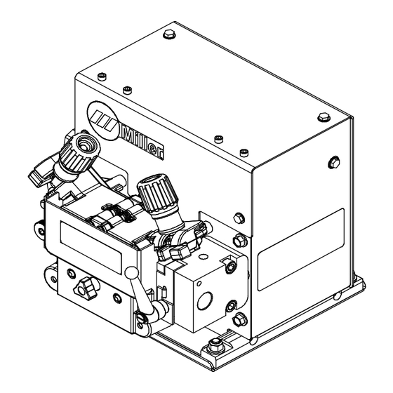
Page 22: Overall Dimensions And Mounting Hole Layout
4-6. Overall Dimensions And Mounting Hole Layout Wire Drive Assembly Inches Millimeters *254 8.75 *Length includes gas filter OM-273476 Page 16... - Page 23 Mounting Holes Inches Millimeters 7.250 0.626 7.666 3.500 4.351 3.696 3.569 3.250 OM-273476 Page 17...
-
Page 24: Section 5 - Installation
SECTION 5 – INSTALLATION 5-1. Typical Equipment Location ST-131 138-A 4 Weld Control 7 Automatic Welding Gun 1 Welding Power Source 5 Spool Support 2 Gas Cylinder 3 Side Beam 6 Wire Drive Assembly 5-2. Shielding Gas And Cooler Connections (CE Model) Turn off power before making connections. -
Page 25: Connecting Weld Output Cable
5-3. Connecting Weld Output Cable Turn off power before connecting control cables. Failure to properly connect weld cables may cause excessive heat and start a fire, or damage your tools/ machine. Ensure all connections are tight. Terminal Connection Do not place anything between weld cable allen_wrench allen_set flathead... -
Page 26: Installing Welding Gun
5-4. Installing Welding Gun 1 Power Clamp Knob 2 Gun Locking Tab 3 Gun Locking Tab Rotated 180 Degrees 4 Power Pin Groove 5 Gun Connection End 6 Installing With Accu-Mate Connection Loosen power clamp knob to allow power pin of gun to clear the gun locking tab. Push power pin into power clamp as far as possible to align the groove in the power pin of the gun with the gun locking tab. -
Page 27: Installing Wire Guides And Drive Rolls
5-5. Installing Wire Guides And Drive Rolls Ref: 301207-014 / Ref: 274356-B 9 Thumb Screw Pull drive roll shaft and remove drive roll car- Installing Wire Guides And Drive Rolls rier. Install drive roll, rotate securing ring un- til it stops at a detent position, place carrier Install inlet wire guide into anti-wear guide, 1 Drive Roll Tension Assembly back into tension assembly bracket, and se-... -
Page 28: Installing And Threading Welding Wire
5-6. Installing And Threading Welding Wire 6 in. (150 mm) tools/ allen_wrench allen_set flathead philips head wrench crescent wrench WOOD ols/ 15/16 in. pliers needlenose Step 3. Push wire through guides up to drive nonconducting surface and pressing gun knife steelbrush nutdriver �... -
Page 29: Section 6 - Maintenance And Troubleshooting
SECTION 6 – MAINTENANCE AND TROUBLESHOOTING 6-1. Routine Maintenance A complete Parts List is available at www.MillerWelds.com omplete Parts List is available at www.MillerWelds.com SECTION 17 MAINTENANCE & TROUBLESHOOTING Disconnect power before maintaining. � 17-1. Routine Maintenance Service equipment more often if used in severe conditions. �... -
Page 30: Troubleshooting
6-2. Troubleshooting Trouble Remedy Wire feeds, shielding gas flows, but Check and secure weld cable connections (see Section 5-3). electrode wire is not energized. Electrode wire feeding stops or feeds Check welding gun trigger and connection. See gun Owner’s Manual. erratically during welding. -
Page 31: Section 7 - Electrical Diagrams
SECTION 7 – ELECTRICAL DIAGRAMS Figure 7-1. Circuit Diagram OM-273476 Page 25... - Page 32 274640−C OM-273476 Page 26...
- Page 33 Notes...
- Page 35 Effective January 1, 2023 (Equipment with a serial number preface of ND or newer) This limited warranty supersedes all previous Miller warranties and is exclusive with no other guarantees or war- ranties expressed or implied. � Field Options (NOTE: Field options are cov-...
- Page 36 Appleton, WI 54914 USA tact your distributor and/or equipment manu- facturer’s Transportation Department. International Headquarters–USA USA Phone: 920-735-4505 USA & Canada FAX: 920-735-4134 International FAX: 920-735-4125 For International Locations Visit www.MillerWelds.com ORIGINAL INSTRUCTIONS – PRINTED IN USA © Miller Electric Mfg. LLC 2024-02...
Need help?
Do you have a question about the Auto-Continuum Drive CE and is the answer not in the manual?
Questions and answers