Table of Contents
Advertisement
Quick Links
Advertisement
Table of Contents

Related Manuals for Dräger Oxylog


Summary of Contents for Dräger Oxylog
- Page 1 Deutscher Text: Bitte umdrehen...
-
Page 2: Table Of Contents
For correct and effective use of the apparatus owner or operator to the extent that the and to avoid hazards it is essential to read the apparatus has been serviced or repaired by following recommendations and to act accor- personnel not employed or authonzed by dingly’... -
Page 3: Page Lntented Use
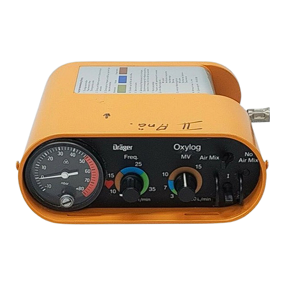
The Oxylog is a ventilator for providing for transferring patients by road or air, controlled ventilation of infants as of 5 for ventilation in the emergency admis- kg body weight and adults on a time- sions department and for transferring... - Page 4 Fig. 2 Oxylog -gas inlets and outlets Compressed-gas connection (male Socket for ventilation tubing thread M 15 x 1) 12 Filter for purifying ambient air 14 Slot for alternative fastening of drawn in carrying strap, e. g. when using holder...
- Page 5 Non-rebreathing valve (Fig. 3, Items 9.1-9.3) 9.1 Cover connection for ventila- taper ISO, dia. 22 for connection of tion tubing (external taper ISO, a PEEP valve. 9.3 Diaphragm (complete) comprising dia. 22) 9.2 Valve housing with patient connec- control diaphragm and checkvalve. The control diaphragm and check tion and waste-gas socket.
-
Page 6: Mounting And Usage Of Holder
16a of holder. Studs must engage in hole in brackets 17. Press on brackets 17 to ensure that the The Oxylog is secured in position in the device is firmly secured in position in rescue vehicle by way of the holder the holder. -
Page 8: Initial Preparation
- the carrying strap can If the carrying strap is constantly in use- be secured in position in the slots in the e. g. including cases where Oxylog is Oxylog housing. See attachment dia- accommodated in holder and in the gram in Fig. - Page 9 Oxator Operating Manual). that red check valve is present and The Oxylog may not be fed via the flow not out of shape. Screw cover to control valves at the Oxator head! valve housing (turn 45” in clockwise direction).
-
Page 11: Determination Of Compressed-Gas Supply And Usage Period
100 min. intervals from inspiration to expiration. The operating prerequisites (at least 2 bar at 60 L/min at Oxylog) are checked indirectly in the MV = 20 L/min setting. Following device upkeep and assembly, Remove catheter adapter from patient the Oxylog is to subjected to the connection;... - Page 12 50%, i. e. the O2 concentration is roughly 50 vol. %. With an MV setting less than 7 To facilitate setting, the ventilation ratio 12 min-’ on the Oxylog is provided with creases up to 80 vol. %. a heart symbol.
-
Page 13: Shut-Down Actions
Use in toxic atmosphere PEEP valve must be removed from the valve of the airway pressure gauge. The Oxylog can also be used for controlled ventilation of injured per- sons in a toxic ambient atmosphere. The Use of pressure limiting valve switch setting >>No Air Mix<<... -
Page 14: Oxylog With Demand Valve To Facilitate Spontaneous Breathing
Time-cycled, volume-constant ventilation and spontaneous breathing in a toxic at- and demand valve switched in parallel mosphere. for supply of spontaneous breathing tive airway pressure (CPAP)! check valve. The following configuration is a prerequisite for use in a toxic atmosphere: M 2 5 5 7 2 8 4 0 8 5 6 8... - Page 15 Replace the cap by applying slight pressure Assembly of the Oxylog: Connect Oxylog and non-rebreathing valve with the ventilation hose. Attach Oxylog to gas supply.
- Page 16 Stripping down Push a catheter adapter size 5 into the patient port of the non-rebreathing hose. valve. Generate a suction with your mouth: valve. Stop sucking: valve anti-clockwise by 45” and remove. Remove the catheter adapter. housing. Cleaning Clean disassembled patient system using water to which a detergent has been added, and dry well.
- Page 17 Establish test setup 1 Conical sealing plug, smallest dia. 4 Patient connection 15mm 5 Catheter connector, dia. 4.5 mm 2 Non-rebreathing valve with check 6 Silicone hose, internal dia. 4 mm, exter- valve nal dia. 6 mm, 100 mm lona 3 Cap of check valve 7 Disposable syringe, IO mL position.
- Page 18 84 07 303 8 Mouthpiece 3 Demand valve 4 Oxylog -10 mbar with your mouth. Set switch at Oxylog to >>Oc(. The unit is sufficiently leakproof if the Fit non-rebreathing valve to silicone pressure change from -6 mbar to hose.
-
Page 19: Care
The component parts can also be washed in the Drager Purfactor@, which Following termination of ventilation the automatically subjects the material to Oxylog is to be prepared for thorough be washed to disinfection and drying. cleaning and disinfection: Remove mask or tube from patient connection of non-rebreathing valve. -
Page 20: Inspection
The valve housing of the Oxylog with de- The device is to be inspected at regular mand valve to facilitate spontaneous brea- 2 years intervals by trained personnel. thing is not suitable for sterilization. The cleaned and dried parts of the patient system can be sterilized in superheated steam. -
Page 21: Trouble Shooting
Establish adequate Device comes to a halt Inadequate supply supply pressure: 2-6 bar on ~~inspirati0r-r~~ pressure Notify Drlger Oxylog defective Inspection Service Eliminate any kinks in Patient cannot exhale or Ventilation tubing tubing only with difficulty kinked... -
Page 22: Technical Data
Flow chopper Principle of operation Time-cycled, volume-constant Control 10-35 min-’ + 20%, Ventilation ratio infinitely adjustable 2-20 L/min + 15%, Minute volume infinitely adjustable gas with O2 drive Switch on SsAir Mixa (with MV greater than 7 L/min) with MV less than 7 L/min 80 vol. - Page 23 Storage conditions: -23°C to +70°c Temperature Humidity 600-l 200 m bar Ambient pressure Materials used Impact-resistant ABS Oxylog housing (Acrylonitrile-Butadiene-Styrene) Silicone rubber Ventilation tubing Non-rebreathing valve PSU (Polysulfone) Housing Silicone rubber Control diaphragm . Non-complmce wtt, these reqummenls w\ll lead to reduced effwency or failure Of dewce functmns...
-
Page 24: Order List
Oxylog time-cycled, volume constant ventilator for controlled ventilation in emergency medicine. Including accessories, comprising: ventilation tubing and non-rebreathing valve. 84 09 585 Oxylog with spontaneous breathing For operation from oxygen cylinder: D 17251 B 03 580 straight valve, filled B 02710... - Page 25 Order No. Name and description Special accessories for pressure reducer D 20225: Connection hoses between Oxylog and cylinder pack option of: a) screw-type both ends, option of b) When using O2 coupling hose M 23874, plug-type via quick-release coupling, thread M 15 x 1 at device end, option of:...
- Page 26 Order No. Name and description For checking compressed-gas supp/y and minute volume: M 25 589 Standard connector, size 5 (stainless steel) For operation with extended ventilation hose: 84 04 063 Connection hose, silicone, 1.1 m M 25 647 Socket IS0 84 06 600 Non-rebreathing valve 2 84 04 063...
-
Page 27: Parts List
No. in Order No. Designation and description 84 09 520 l - 7 Oxyfog with ventilation accessories 84 08 500 84 04 063 Silicone tubing E 1.1 m 84 06 600 Non-rebreathing valve 84 06 585 Cover 84 03 552 Diaphragm 84 06 595 Valve housing... - Page 28 The item Nos. are not identical with the item Nos. in the other figures.
- Page 29 These Instructions for Use apply only to with Serial No.: If no Serial No. has been filled in by provided for general information only and are not intended for use with any specific machine or device. Aktiengesellschaft Germany Moislinger Allee 53 - 55 D-23542 Liibeck 26807 -0 FAX (4 51) 8 82-20 80...
Need help?
Do you have a question about the Oxylog and is the answer not in the manual?
Questions and answers