Table of Contents
Advertisement
Quick Links
Advertisement
Table of Contents

Related Manuals for ABB RS485


Summary of Contents for ABB RS485
- Page 1 RS485 Modbus adapter for RVT Touchscreen Installation and start-up guide...
-
Page 2: Table Of Contents
7.1 Preferred method of testing ................. 17 7.2 Check of identical Slave – Master configuration ..........17 7.3 Check the cabling of the RS485 ................17 7.4 Check the Transmit – Receive indicators ............18 7.5 Check the function called and the register addresses ........18 7.6 Check the data access level and the limited range of data ......... - Page 3 8.2 References ......................22 8.3 Adequate choice of an RS232-RS485 converter at the computer side ....22 Contact us ........................24 RS-485 Table of contents - 3...
-
Page 4: Introduction
1 Introduction 1.1 Intended audience This manual is intended for installers, commissioning people, network managers who need to install an RS485 network, start or maintain a supervision system based on the Modbus protocol. 1.2 Before you start This manual describes the RS485 Modbus adapter. -
Page 5: Overview
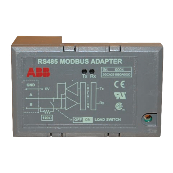
Other ABB controllers may be connected with the adapter. CAUTION: Be careful that the RS485 MODBUS ADAPTER is the one with a GREEN text colour (3.3V power supply). The one with a WHITE text colour is reserved for the old model (5V power supply). -
Page 6: Serial Interface Considerations
3 Serial interface considerations The Modbus protocol communicates with the instrumentation by means of an industry standard serial interface. This interface may be RS-232, RS-422 or RS-485. Some systems may also support the protocol over other busses or networks, such as Ethernet. An RS-232 interface allows only two devices to be connected together. -
Page 7: Rs-422 Interface
The general rule is to add them only if needed. The resistors are typically 120 ohms, and installed across the Transmit and Receive wire pairs. Normally, one resistor is installed at each end of each pair of wires. RS485 Serial interface considerations - 7... -
Page 8: Shielding And Grounding Considerations
(Belden 9841 for 2-wire and 9729 for 4-wire or equiv.). 3.10 Network topology Various kinds of network topologies may be done on the basis of an RS485 Modbus network. The Modbus network may be managed by a computer collecting data. Typically this computer runs an OPC server connected to a plant intranet. - Page 9 Various kind of RS485 to RS232 converters exists. To bridge the Modbus network to another kind of software protocol, various kinds of protocol converters may be used. They are often called ‘protocol gateway: Modbus to Profibus, Ethernet, CAN … RS485 Serial interface considerations - 9...
-
Page 10: Rs485 Modbus Adapter
4 RS485 Modbus adapter The RS485 Modbus adapter enables the connection of the controller to an RS485 Modbus network. 4.1 Main features The adapter is self powered through the power supply of the controller. Advantage: an external power supply is not needed. -
Page 11: Mounting
Operating ambient temperature: -20 to +70 °C Number of nodes (Tx drive): 32 max Rx loading: receiver impedance is 1 unit load per RS485 Modbus adapter Size of the Link: 247 stations including repeaters (31 stations and 1 repeater per segment) ... -
Page 12: Commissioning Process
Ensure that all connections are tight. If the RS485 Modbus adapter is one of the two ending station on the communication line put the load termination switch in the ‘ON ‘position. If not, put it in the ‘OFF ‘position. -
Page 13: To Set The Communication Lock Parameter
Depending on the way the controller is connected to the Modbus network, different ways of testing may be chosen. The user can find much application on the internet to scan Modbus devices and test communication. In case of problem, please refer to the troubleshooting paragraph. RS485 RS485 Modbus adapter - 13... -
Page 14: Modbus Protocol Overview
It determines how information will be packed into the message fields and decoded. Modbus defines two transmission modes: ASCII or RTU. Only RTU mode will be used here. The mode and serial parameters must be the same for all devices on a Modbus network. 14 – Modbus protocol overview RS485... -
Page 15: Data Addresses In Modbus Messages
Device specific (see Modbus data table of the device) Mask Write 4X registers 4XXXX And/Or write of a holding register 4XXXX Reads a set of holding registers and writes a set of holding Read/Write 4X registers registers in one query RS485 Modbus protocol overview - 15... -
Page 16: Data Access
6 Data access 6.1 Access levels Some access levels must be set to allow parameters to be changed. Here are some access levels used in the RVT. SET MODE: The RVT must be in the Set Mode to allow parameter modifications. LOCKING SWITCH: the locking switch has to be released BANK SETTINGS: the parameter bank settings must be set as Unlocked (for more information on these settings, please refer to the RVT Installation and Operating manual). -
Page 17: Troubleshooting
RS232 communications ports. In these instances a converter will be needed to convert the RS232 signals to the RS485 standard used by the controller. Only when the Modbus Master is running on hardware fitted with RS485 ports is a converter unnecessary. -
Page 18: Check The Transmit - Receive Indicators
The Transmit Led (green Led) indicates that a Modbus response is being transmitted from the RS485 Modbus adapter. If the Rx Led and the Tx Led never lit, the problem may come from: The wires of the RS485 cable are not properly fixed or cabled ... -
Page 19: Counters And Loopback Diagnostics
The user can find much application on the internet to scan Modbus devices and test communication. Look in the documentation of the controller and the corresponding Modbus data table for appropriate information. Look in the Modbus protocol for more information on Modbus. RS485 Troubleshooting - 19... -
Page 20: Appendix
HEX ranges from 0 to 15, represented by 0 to 9 and A to F. Human-Machine Interface (formerly MMI) Industrial Umbrella concept for ABB’s vision for enterprise automation. Industrial Architecture The architecture of the Industrial system. The architecture... - Page 21 Modbus adapter It is an optional small interface module through which the controller is connected to an external Modbus serial communication bus. It performs an optical to RS485 conversion. The communication with the Modbus adapter is activated with a parameter.
- Page 22 Modicon Modbus Protocol Reference Guide (PI–MBUS–300 Rev. J) 8.3 Adequate choice of an RS232-RS485 converter at the computer side In a RS-485 network, a control of the direction is needed to alternate between transmission and reception. Two cases may be found: ...
- Page 23 An also important feature is the isolation between the RS-232 side and the RS-485 side to avoid ground loops and to work safely. Finally, port powered converters should be considered carefully as some computers don't have sufficient power to feed efficiently the RS-232-RS-485 converter. RS485 Appendix - 23...
- Page 24 AB B n.v. P ower Quality P roduc ts Avenue C entrale 10 Zoning Industriel de J umet B -6040 C harleroi (J umet), B elgium Phone: +32(0) 71 250 811 Fax: +32 (0) 71 344 007 E-Mail: Power.Quality@be.abb.com www.abb.c om/lowvoltage...