Table of Contents
Advertisement
Quick Links
Advertisement
Table of Contents

Related Manuals for ABB RCNA-01


Summary of Contents for ABB RCNA-01
- Page 1 ABB Drives User’s Manual ControlNet Adapter Module RCNA-01...
- Page 3 ControlNet Adapter Module RCNA-01 User’s Manual 3AFE64506005 Rev B EFFECTIVE: 21.10.2008 © 2008 ABB Oy. All Rights Reserved.
-
Page 5: Safety Instructions
Safety instructions Overview This chapter states the general safety instructions that must be followed when installing and operating the RCNA-01 ControlNet Adapter module. The material in this chapter must be studied before attempting any work on the unit. In addition to the safety instructions given below, read the... - Page 6 Safety instructions...
-
Page 7: Table Of Contents
Network overview ..........15 The RCNA-01 ControlNet Adapter module ......16 Compatibility . - Page 8 RCNA-01 connections ........
- Page 9 RCNA-01 ........
- Page 10 Table of contents...
-
Page 11: Introduction
The guide is intended for the people who are responsible for installing, commissioning and using a ControlNet Adapter module with an ABB drive. The reader is expected to have a basic knowledge of electrical fundamentals, electrical wiring practices, the drive, the use of the drive control panel, and the ControlNet protocol. -
Page 12: Conventions Used In This Guide
Programming explains how to program the drive before the communication through the adapter module can be started. Communication contains a description of the ControlNet functionality supported by the RCNA-01. Fault tracing describes how to diagnose the ControlNet connection during installation, commissioning, and normal operation. -
Page 13: Product And Service Inquiries
RCNA-01 ControlNet Adapter module The RCNA-01 Adapter module is one of the optional fieldbus adapter modules available for ABB drives. The RCNA-01 is a device through which an ABB drive is connected to a ControlNet serial communication bus. Output In this manual, the word ’output’ is used to describe data flow from the ControlNet Scanner. - Page 14 Introduction...
-
Page 15: Overview
Overview Overview This chapter contains a short description of ControlNet network, the RCNA-01 Adapter module, a delivery checklist, and warranty information. Further information can be obtained from www.controlnet.org. Network overview The media for the fieldbus is a RG-6 quad shielded cable or fibre with support for media redundancy. -
Page 16: The Rcna-01 Controlnet Adapter Module
• read and write drive parameter values • reset a drive fault. A connection to the RCNA-01 ControlNet Adapter can be opened from a ControlNet scanner. The size of the connection can be up to 450 bytes in each direction. -
Page 17: Compatibility
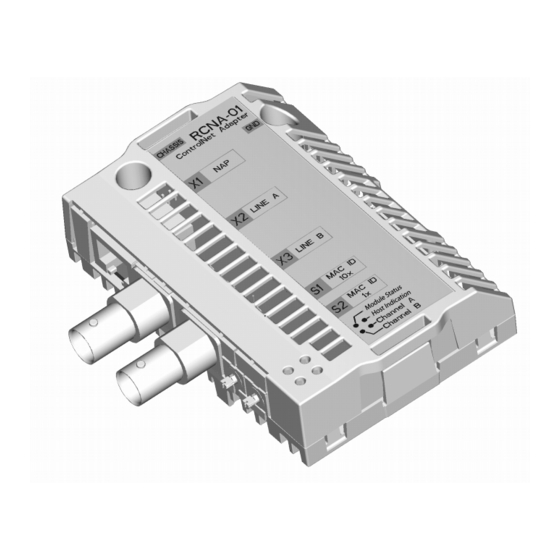
Diagnostic LEDs (chapter Fault tracing) ABB Drive Figure 1. The construction of the ControlNet link and the layout of the RCNA-01 Adapter module Compatibility The RCNA-01 is compatible with all scanners working according to the ControlNet International ControlNet specifications. Overview... -
Page 18: Delivery Check
Delivery check The option package for the RCNA-01 ControlNet Adapter module contains: • ControlNet Adapter module, type RCNA-01 • two screws (M3x10) • this manual. Warranty and liability information The manufacturer warrants the equipment supplied against defects in design, materials and workmanship for a period of twelve (12) months after installation or twenty-four (24) months from date of manufacturing, whichever first occurs. -
Page 19: Mechanical Installation
Hardware Manual. Mounting The RCNA-01 is to be inserted into its option slot inside the drive. The module is held in place with plastic retaining clips and two screws. The screws also provide the earthing of the I/O cable shield connected to the module, and interconnect the GND signals of the module and the control board of the drive. - Page 20 Mechanical installation...
-
Page 21: Electrical Installation
Electrical installation Overview This chapter contains: • general cabling instructions • instructions on setting the module node address number • instructions for connecting the module to the ControlNet bus. WARNING! Before installation, switch off the drive power supply. Wait five minutes to ensure that the capacitor bank of the drive is discharged. -
Page 22: Rcna-01 Connections
RCNA-01 connections ControlNet connection The bus cable is connected to the BNC connectors A and/or B on the RCNA-01. If redundant operation is desired, both connectors are used, otherwise connector A or B is used. ControlNet bus termination The ControlNet bus line must be terminated with 75 ohm resistor. -
Page 23: Programming
Scanner. Please refer to the Scanner documentation for information on configuring the system for communication with the RCNA-01. Configuration (EDS) files for the RCNA-01 are available at www.abb.com. ControlNet connection configuration The detailed procedure of activating the module for communication with the drive is dependent on the drive type. -
Page 24: Control Locations
ABB drives can receive control information from multiple sources including digital inputs, analogue inputs, the drive control panel and a communication module (e.g. RCNA-01). ABB drives allow the user to separately determine the source for each type of control information (Start, Stop, Direction, Reference, Fault Reset, etc.). - Page 25 Input I/O Par 1 0 ... 32767 Input I/O Par 2 0 ... 32767 Input I/O Par 3 0 ... 32767 Input I/O Par 4 0 ... 32767 Output I/O Par 5 0 ... 32767 Output I/O Par 6 0 ... 32767 Output I/O Par 7 0 ...
- Page 26 71, but contain additional space for user-mapped data. The instances 100, 101, 102 and 103 are so-called vendor-specific instances as defined by ABB, i.e. the control word, status word, speed reference and speed actual value are defined by the ABB Drives communication profile.
- Page 27 The static/dynamic property indicates whether the data length of the instance is fixed or adjustable. Output instances Instance Assembly Static/Dynamic Basic speed control output Static Extended speed control output Static User transparent assembly Static Vendor specific assembly Dynamic Extended speed control plus Dynamic drive parameters Input instances...
- Page 28 Possible instance combinations Communication profile Output instance Input instance to be used ABB Drives profile ABB Drives profile ABB Drives profile ABB Drives profile Generic Drive profile Generic Drive profile Generic Drive profile Generic Drive profile Selecting an invalid combination will reset the module and automatically configure the instances as follows: 1) If the output instance is invalid, instance 20 will be selected.
- Page 29 The content is defined by a decimal number in the range of 0 to 32767 as follows: not used 1 - 99 data set area of the drive 101 - 9999 parameter area of the drive 10000 - 32767 not supported by the drive The data set area is allocated as follows: data set 1 word 1 data set 1 word 2...
- Page 30 The content is defined by a decimal number in the range of 0 to 32767 as follows: not used 1 - 99 data set area of the drive 101 - 9999 parameter area of the drive 10000 - 32767 not supported by the drive The data set area is allocated as follows: data set 1 word 1 data set 1 word 2...
- Page 31 26 VSA I/O Size Defines the number of user-mapped data words in Vendor Specific assemblies (instances 102, 103, 121 and 171). The value of this parameter directly specifies the size (in words) of instances 102 and 103, whereas the size of instances 121 and 171 will be the value of this parameter plus two words.
- Page 32 Programming...
-
Page 33: Communication
RCNA-01 and the configuration of the scanner. For detailed information on ControlNet communication, refer to ControlNet specifications. Introduction to ControlNet The interface from the fieldbus towards the RCNA-01 is based on the standard ControlNet objects and vendor specific objects. The RCNA-01 has the following objects included: Object Name... -
Page 34: Assembly Object
I/O Assembly Instances may also be referred to as Block Transfer of data. Intelligent devices realising a Functional Profile, such as the RCNA-01, have several objects. Since it is not possible to transmit more than one object data through a single connection, it is practical and more efficient to group attributes from different objects into a single I/O connection using the Assembly object. - Page 35 CONTROL assembly is used, it must be ensured that the fieldbus is selected as the drive control source and fieldbus specific (Generic Drive profile) Control/Status Word format is selected instead of ABB Drives profile. EXTENDED SPEED CONTROL assembly The EXTENDED SPEED CONTROL assembly is defined by the ControlNet AC/DC Drive Profile.
- Page 36 * See BASIC SPEED CONTROL assembly for information on speed actual value scaling. USER TRANSPARENT assembly USER TRANSPARENT assembly allows the use of the ABB Drives communication profile. The format of the output assembly Instance 100 (Output assembly) Byte Bit 7...
- Page 37 VENDOR SPECIFIC assembly VENDOR SPECIFIC assembly allows the use of the ABB Drives communication profile. The format of the output assembly is: Instance 102 (Output assembly) Byte Bit 7 Bit 6 Bit 5 Bit 4 Bit 3 Bit 2 Bit 1...
- Page 38 Note: If the BASIC SPEED CONTROL or the EXTENDED SPEED CONTROL assembly is used, it must be ensured that the fieldbus is selected as the drive control source and fieldbus specific (Generic Drive profile) Control/Status Word format is selected instead of ABB Drives profile. Communication...
- Page 39 EXTENDED SPEED CONTROL PLUS DRIVE PARAMETERS assembly EXTENDED SPEED CONTROL PLUS DRIVE PARAMETERS assembly allows the use of ControlNet AC/DC Drive Profile with additional user-mapped parameters. The format of the output assembly is: Instance 121 (Output assembly) Byte Bit 7 Bit 6 Bit 5 Bit 4 Bit 3 Bit 2 Bit 1...
- Page 40 Input I/O 10 to 32 can be configured through the Vendor Specific ControlNet Configuration object, Class 0x91. Note: The maximum number of input I/O's supported by the drive depends on the drive type and application. The format of the input assembly is: Instance 171 (Input assembly) Byte Bit 7 Bit 6...
-
Page 41: Class Objects
The value of Input I/O 1 to 9 is read from the data word or drive parameter defined by Input I/O Par 1 to 9 respectively. See chapter Programming. Input I/O 10 to 32 can be configured through the Vendor Specific ControlNet Configuration object, Class 0x91. - Page 42 The list of device types is managed by ControlNet International. It is used to identify the device profile that a particular product is using. Product Code Every ABB drive type or application of the drive has a dedicated product code. Communication...
- Page 43 Revision Revision attribute, which consists of Major and Minor Revisions, identifies the Revision of the item the Identity Object is representing. Status This attribute represents the current status of the entire device. Its value changes as the state of the device changes. The Status attribute is a WORD, with the following bit definitions: Bit(s) Type/Name...
-
Page 44: Assembly Object, Class 0X04
Serial Number: This attribute is a number used in conjunction with the Vendor ID to form a unique identifier for each device on ControlNet. Product Name: This text string should represent a short description of the product/ product family represented by the product code in attribute 3. Assembly Object, Class 0x04 The Assembly Object binds attributes of multiple objects which allows data to or from each object to be sent or received over a... -
Page 45: Controlnet Object, Class 0Xf0
Instance Attribute Service Description 0x14 Get/Set Accesses assembly instance 20 as a byte (20) array. 0x15 Get/Set Accesses assembly instance 21 as a byte (21) array. 0x46 Get/Set Accesses assembly instance 70 as a byte (70) array. Set has no effect, since instance 70 contains actual data from the drive. - Page 46 Class attributes ID# Attribute Services Description Value Data type name 0x02 Max Maximum instance Node UINT instance number specific Instance 0x01, Attributes ID# Attribute Services Description Data name type 0x81 Current link Get Attribute Current link configuration Struct of config Single parameters 34 bytes...
- Page 47 ID# Attribute Services Description Data name type NUT overflow No unscheduled time in NUT USINT (all time used for scheduled transmissions) Slot overloads More scheduled data queued USINT for one NUT than allowed by sched_max_frame parameter. Blockages Single Lpacket size exceeds USINT sched_max_frame parameter.
-
Page 48: Motor Data Object, Class 0X28
ID# Attribute Services Description Data name type Vendor USINT specific Reserved Reserved Byte 0x83 Station status Station status Struct of 6 bytes SMAC ver MAC implementation USINT Vendor USINT specific Channel state Channel LED’s redundancy Byte warning and active bits 0x84 Mac ID Get_Attribute_ Mac ID switch and current... -
Page 49: Control Supervisor Object, Class 0X29
Instance 0x01, Attributes ID# Attribute Services Description Motor Default, Data name Type Min, Max type 0x03 Motor Type Get 1 - PM DC Motor AC/DC 7, 1, 10 UINT 2 - FC DC Motor 3 - PM Synchronous Motor 4 - FC Synchronous Motor 5 - Switched Reluctance Motor 6 - Wound Rotor Induction... - Page 50 Services Supported Service Code No. Service Name 0x05 Reset 0x0E Get Attribute Single 0x10 Set Attribute Single Instance 0x01, Attributes ID# Attribute Services Description Data name type 0x03 Run 1 Get, Set 0 = Stop, 1 = Run BOOL 0x04 Run 2 Get, Set 0 = Stop, 1 = Run BOOL 0x05 Net Control...
- Page 51 ID# Attribute Services Description Data name type 0x14 Net Idle Get, Set Action taken when the master goes to idle UINT8 state in Generic drive profile 0 = Stop 1 = Freeze (keep running) 2 = Fault Supported only with assembly instances 20, 21 and 121 Supported only with assembly instances 21 and 121 Supported only with assembly instances 70, 71 and 171 Supported only with assembly instances 71 and 171...
- Page 52 Table 2. Run/Stop event matrix RunFwd RunRev Trigger event Run type Stop → RunFwd RunRev → No Action → → No Action RunRev → RunFwd → Non Existent Power off Power on ALM=1 Faulted Startup Power on FaultRst Not Ready DEC=0 ALM=1 Fault Stop...
-
Page 53: Ac/Dc-Drive Object, Class 0X2A
AC/DC-Drive Object, Class 0x2A This object models the functions specific to an AC or DC Drive. Services Supported Service Code No. Service Name 0x0E Get Attribute Single 0x10 Set Attribute Single Communication... - Page 54 Instance 0x01, Attributes ID# Attribute Services Description Data name type 0x03 At Reference Frequency arrival BOOL 0x04 NetRef Get, Set Requests torque or speed reference BOOL to be local or from the network. 0 = Set Reference not DN Control 1 = Set Reference at DN Control Note that the actual status of torque or speed reference is reflected in...
-
Page 55: Vendor Specific Object, Class 0X90
Vendor Specific Object, Class 0x90 Services Supported Service Code No. Service Name 0x0E Get Attribute Single 0x10 Set Attribute Single Instance 0x00, Attributes Attribute Services Description Data name type 0x02 Max instance Get Maximum number of instances UINT16 in this Class The Vendor Specific Object, Class 0x90, enables access of drive parameter and data sets. - Page 56 Instance 0x01, Attributes ID# Attribute name Services Description 0x01 Parameter Index Get, Set Group 1 Index 1 0x02 Parameter Index Get, Set Group 1 Index 2 0x63 Parameter Index Get, Set Group 1 Index 99 Instance 0x02, Attributes ID# Attribute name Services Description 0x01 Parameter Index Get, Set...
-
Page 57: Vendor Specific Controlnet Configuration, Class 0X91
Vendor Specific ControlNet Configuration, Class 0x91 This object is used when more I/O data than listed in Table 1. The RCNA-01 configuration parameters of the Configuration chapter needs to be handled. In this object 32 words of Input and Output data can be used. - Page 58 Services Supported Service Code Service Name 0x05 This Reset command will clear all attributes in one instance to zero. I.e. a reset of Class 91, Instance 1 will set all output parameters to zero. 0x0E Get Attribute Single 0x10 Set Attribute Single Instance and Attributes Two instances are supported by Class 0x91: •...
- Page 59 Instance 0x02, Attributes Attribute name Default, Data type Min, Max 0x01 Input I/O parameter 1 0, 0, 32767 UINT16 0x02 Input I/O parameter 2 0, 0, 32767 UINT16 0x03 Input I/O parameter 3 0, 0, 32767 UINT16 0x04 Input I/O parameter 4 0, 0, 32767 UINT16 0x20 Input I/O parameter 32...
- Page 60 Communication...
-
Page 61: Fault Tracing
Fault tracing RCNA-01 status codes The status of the ControlNet module is indicated by a ‘fieldbus status’ parameter in the drive application program (refer to the drive documentation). IDLE The drive could not initiate communication with the ControlNet Module. EXECUT. INIT The module is initialising and performing self-test. - Page 62 Module Host Indication status Channel B Channel A Name Colour Function A and B: OFF Steady - Module is not initialised. A and B: RED Steady - Faulted unit, must be restarted or repaired A and B: RED/GREEN Alternating - Self testing bus controller A and B: RED Flashing - Incorrect node configuration, duplicate MacID etc.
-
Page 63: Installation Problems
• Check that the RCNA-01 module is properly inserted into the option slot. • Check the fastening of the RCNA-01 module with the 2 screws. Drive setup The fieldbus parameter group is not shown on the panel: • Enable the RCNA-01 by setting the appropriate drive parameter. -
Page 64: Plc Programming
• Check that the control location parameters of the drive are set to use the RCNA-01 as the source of the required command. • Check that the drive is in REMOTE control. PLC programming The PLC program is beyond ABB Drives support. -
Page 65: Technical Data
Technical data RCNA-01 Enclosure: 34 mm 62 mm Mounting: Into an option slot inside the drive Degree of protection: IP 20 Settings: Through drive parameters and/or rotary switches Ambient conditions: The applicable ambient conditions specified for the drive in its Hardware Manual are in effect. -
Page 66: Fieldbus Link
Current consumption: • 260 mA max. (5 V), supplied by the control board of the drive General: • Estimated min. lifetime: 100 000 h • All materials are UL/CSA approved • Complies with EMC Standards EN 50081-2 and EN 50082-2 Fieldbus link Compatible devices: Any ControlNet scanner Medium: RG-6 quad shielded cable (coax) - Page 68 ABB Oy ABB Inc. AC Drives Automation Technologies P.O. Box 184 Drives & Motors FIN-00381 HELSINKI 16250 West Glendale Drive FINLAND New Berlin, WI 53151 Telephone +358 10 22 11 Telefax +358 10 22 22681 Telephone 262 785-3200 Internet www.abb.com...