Jet 16-32 Plus Operating And Parts Manual
Jet tools operating instructions drum sander 16-32 plus
Hide thumbs
Also See for 16-32 Plus:
- Operating instructions and parts manual (36 pages) ,
- Operating instructions manual (21 pages) ,
- Specifications (4 pages)
Table of Contents
Advertisement
Advertisement
Table of Contents

Related Manuals for Jet 16-32 Plus


Summary of Contents for Jet 16-32 Plus
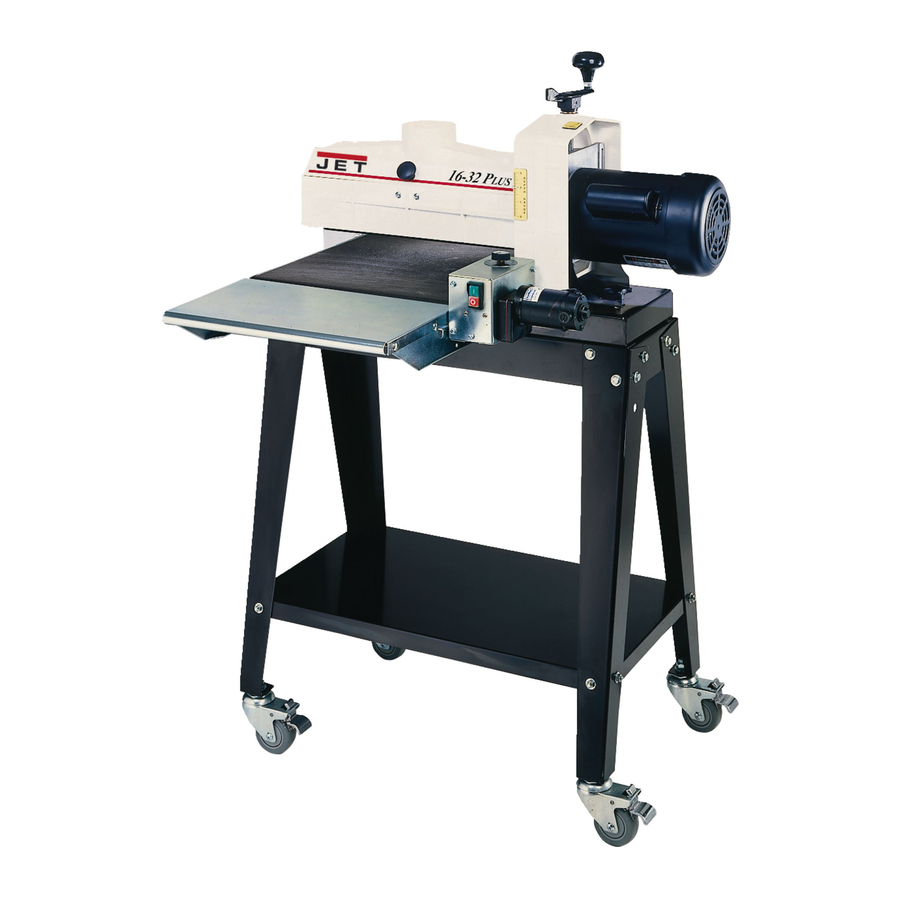
- Page 1 Operating Instructions and Parts Manual Drum Sander Model 16-32 Plus shown with optional casters (98-0130) and infeed/outfeed tables (98-1601) WMH TOOL GROUP 2420 Vantage Drive Elgin, Illinois 60123 Part No. M-629004 Ph.: 800-274-6848 Revision A 3/06 www.wmhtoolgroup.com Copyright © WMH Tool Group...
-
Page 2: Warranty And Service
WARRANTY AND SERVICE WMH Tool Group, Inc., warrants every product it sells. If one of our tools needs service or repair, one of our Authorized Service Centers located throughout the United States can give you quick service. In most cases, any of these WMH Tool Group Authorized Service Centers can authorize warranty repair, assist you in obtaining parts, or perform routine maintenance and major repair on your JET tools. -
Page 3: Table Of Contents
Introduction...6 Specifications ...6 Features and Terminology ...7 Unpacking ...8 Contents of Boxes...8 Assembling the Stand ...9 Casters (Optional Accessory) ...9 Assembling the Sander...10 Installing Drum Head...10 Installing Conveyor...10 Infeed/Outfeed Tables (Optional Accessory)...11 Dust Collection...12 Installing Abrasives ...12 Grounding Instructions ...14 Extension Cords...15... -
Page 4: Warning
5. Do not use this sander for other than its intended use. If used for other purposes, WMH Tool Group disclaims any real or implied warranty and holds itself harmless from any injury that may result from that use. - Page 5 29. Keep your hands clear when feeding parts onto the conveyor. The part will be forced down as it begins to feed, causing a pinching action between the part and the conveyor bed. Never reach into a running machine. Turn off sander and disconnect from power before attempting to retrieve parts from within the machine.
-
Page 6: Introduction
This manual is provided by WMH Tool Group covering the safe operation and maintenance procedures for a JET Model 16-32 Plus Drum Sander. This manual contains instructions on installation, safety precautions, general operating procedures, maintenance instructions and parts breakdown. This machine has been designed and constructed to provide years of trouble free operation if used in accordance with instructions set forth in this manual. -
Page 7: Features And Terminology
Features and Terminology The illustration below shows the major components and features of the 16-32 Plus Sander. These are referenced throughout the manual and will help to familiarize you with the operation and functions of the machine. Figure 1... -
Page 8: Unpacking
Report any damage immediately to your distributor and shipping agent. Do not discard any shipping material until the Drum Sander is assembled and running properly. Compare the contents of your boxes with the following parts list to make sure all parts are intact. -
Page 9: Assembling The Stand
Assembling the Stand (Refer to Figure 4. If further clarification is needed, consult the parts breakdown on page 28.) Tools required for Stand assembly: Ratchet wrench with 1/2” socket 1. Assemble legs (H) to outside of Short Rails (L) using carriage bolts (N) and flanged lock nuts (O). Finger tighten only. -
Page 10: Assembling The Sander
(Figure 6). [NOTE:The four holes at the center of the long rails are not used with the 16-32 Plus.] 6. Fasten base to stand (from beneath) with the four screws and flat washers that you removed from the plywood boards. -
Page 11: Infeed/Outfeed Tables (Optional Accessory)
Infeed/Outfeed Tables (Optional Accessory) The sander should be bolted to the stand or a work table when using these table extensions. Maximum working load of a table is 35 pounds. 1. Install a bracket (A, Figure 8) to the two holes in the sander base with a 9/16”... -
Page 12: Dust Collection
2-1/2” hose (see “Optional Accessories” on page 26). Installing Abrasives An 80-grit abrasive strip is already installed on the drum of your sander, and one box of assorted grit Ready to Wrap abrasives is also supplied. Page 25 offers information on the types of abrasive and their recommended uses. - Page 13 8. You can use your fingers to work the infeed take-up fastener, but it will be more convenient to use the TUFTool supplied with your sander. Hold the TUFTool with the red end pointing away from you (Figure 14) and insert its hook into the outside hole of the fastener lever (see Figure 16).
-
Page 14: Grounding Instructions
Repair or replace a damaged or worn cord immediately. As received from the factory, your drum sander is intended for use on a 20 amp, 110V dedicated circuit, which has an outlet and a plug that look like the ones illustrated in Figure 17. -
Page 15: Extension Cords
1/16” (or 1/4 turn = approx. 1/64”). Switch Lock Unauthorized use of the sander can be prevented by pulling out the key (Figure 20). Press switch to OFF position before removing the key. When the key is removed, the machine can not be started. -
Page 16: Dust Cover Latch
IMPORTANT: The conveyor belt has been over- tensioned for shipping purposes. It must be re- tensioned before operating the sander. Belt Tension: To adjust the tension of the conveyor belt, first adjust the take-up screw nut (Figure 22) on both sides of the conveyor to obtain approximately equal tension on both sides of the belt when taut. -
Page 17: Sanding Drum Alignment
First inspect the alignment with a gauge of some kind. The following procedure uses a steel straight edge as a gauge. 1. Unplug sander from power source. 2. Open the dust cover and remove the abrasive strip from the drum. -
Page 18: Drum Height Control Adjustment
Fine-Tuning Drum Alignment (for sanding boards wider than the drum) NOTE: Perform this alignment after you are familiar with sander operation. This is an operational test. When sanding boards wider than the drum, drum alignment is critical and must be exactly level to slightly high on the outboard end to prevent ridges from forming on the board. -
Page 19: Tension Roller Alignment
(i.e. those set too high, rendering them non-functional) could allow kick-back of pieces being sanded. 1. Unplug sander from power source and remove abrasive from drum. 2. Loosen all four hex nuts on the bearing bolts (A, Figure 29). This will allow both tension rollers to drop to their lowest position. -
Page 20: Operation
Tips for Maximum Performance The versatility designed into the 16-32 Plus drum sander allows it to be used for a wide variety of tasks that will boost the return on your investment. -
Page 21: Multiple-Piece Sanding Runs
Be aware that the sander will remove cups and crowns in the workpiece; consider this when measuring and processing stock to the same thickness. -
Page 22: Tracker Kit (98-0080)
6. On the underside of the conveyor bed, there are U-channels welded to the bed. The Tracker is positioned on the inside of the first U-channel on the infeed side of sander (the U-channel closest to the rubber covered drive roller and gear motor). The back of the Tracker is magnetized and will stick to the side wall of the conveyor bed. -
Page 23: Maintenance
Remedy Check plug connection. Make sure fuse is not blown/circuit breaker is not tripped. Push the circuit breaker button on the sander motor to re-set. Replace switch. Reduce depth of cut; use coarser grit; reduce feed rate. Adjust shaft coupler. - Page 24 Readjust height control. See pages 18-19. Allow motor to cool and re-set overload button. Connect sander to a dedicated circuit. Have a certified electrician correct any shop wiring problem. Use a shorter or heavier gauge extension cord (see Figure 19).
-
Page 25: Abrasives
Abrasives The abrasive material you choose will have a substantial effect on the performance of your sander. Variations in paper type, weight, coating and durability all contribute to achieving your desired finish. JET Abrasives are available in Ready-To- Wrap pre-cut lengths or in the convenient Ready-To-Cut pre-marked box. -
Page 26: Optional Accessories
Optional Accessories 61-1012 Poly Conveyor Belt 98-0130 Locking Casters, set of 4 98-1601 Infeed/Outfeed Tables 80-2900 Elbow, 90° for 2.5” dust collection hose 80-2910 Adaptor, for 4” port to 2.5” dust collection hose 60-6000 Ready-To-Wrap Assortment Package, Grits: 36 (1 strip), 80 (2 strips),120 (1 strip) 60-6024 Ready-To-Wrap Abrasive Strip, 24 Grit, (4 wraps in a box) -
Page 27: Parts List: Stand Assembly
Parts List: Stand Assembly Index No. Part No. Description Size 1A...40-4040... Left Leg ..2 1B...40-4041... Right Leg (with TufTool holder) ..2 2...40-4042... Long Rail ..2 3...40-4043... Short Rail..2 4...98-1610... Shelf ..1 5...10-1206... -
Page 28: Conveyor And Motor Assembly
Conveyor and Motor Assembly... -
Page 29: Parts List: Conveyor And Motor Assembly
Parts List: Conveyor and Motor Assembly Index No. Part No. Description Size 1...3237359... Gear Motor ... 90 VDC... 1 2...72-6014... Large Strain Relief ..1 3...72-5336... Cord Set ... 115V – 75” ... 1 4...40-4017W ... Control Housing Bracket ..1 5...TS-0206022 ... -
Page 30: Drum Head Assembly
Drum Head Assembly... -
Page 31: Parts List: Drum Head Assembly
Parts List: Drum Head Assembly Index No. Part No. Description 34 ...70-4101... Motor... 1-1/2HP, 110-120V ... 1 ...70-4101-1 ... Motor Fan (not shown) ..1 ...70-4101-2 ... Motor Fan Cover (not shown)..1 ...JWTS10-MRS ... Motor Re-set Switch (not shown) ..1 ...C-300125A... -
Page 32: Parts List: Infeed/Outfeed Tables (Optional Accessory)
95 ...51-2200... Coupler Kit (includes index #56,67,58) (not shown)... 98 ...12-9001... Nylon Insert Lock Nut... #6-32 ... 1 99 ...98-0060... TufTool ...99-1002... 16-32 Sander Demo Video (not shown)..1 Parts List: Infeed/Outfeed Tables (Optional Accessory) Index No. Part No. -
Page 33: Electrical Connections
Electrical Connections... - Page 34 NOTES...
- Page 36 WMH Tool Group 2420 Vantage Drive Elgin, Illinois 60123 Phone: 800-274-6848 www.wmhtoolgroup.com...
Need help?
Do you have a question about the 16-32 Plus and is the answer not in the manual?
Questions and answers