Table of Contents
Advertisement
This .pdf document is bookmarked
Operating Instructions and Parts Manual
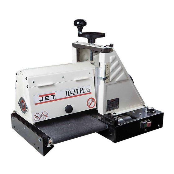
Drum Sander
Model: 10-20 Plus
Shown with optional accessories
WALTER MEIER (Manufacturing) Inc.
427 New Sanford Road
LaVergne, Tennessee 37086
Part No. M-628900
Ph.: 800-274-6848
Revision C1 01/2010
www.waltermeier.com
Copyright © 2010 Walter Meier (Manufacturing) Inc.
Advertisement
Table of Contents

Related Manuals for Jet 10 Plus


Summary of Contents for Jet 10 Plus
- Page 1 This .pdf document is bookmarked Operating Instructions and Parts Manual Drum Sander Model: 10-20 Plus Shown with optional accessories WALTER MEIER (Manufacturing) Inc. 427 New Sanford Road LaVergne, Tennessee 37086 Part No. M-628900 Ph.: 800-274-6848 Revision C1 01/2010 www.waltermeier.com Copyright © 2010 Walter Meier (Manufacturing) Inc.
-
Page 2: Warranty And Service
Walter Meier is consistently adding new products to the line. For complete, up-to-date product information, check with your local Walter Meier distributor, or visit waltermeier.com. WARRANTY JET products carry a limited warranty which varies in duration based upon the product (MW = Metalworking, WW = Woodworking). WHAT IS COVERED? This warranty covers any defects in workmanship or materials subject to the exceptions stated below. -
Page 3: Table Of Contents
Drum Height Control Adjustment ....................18 Troubleshooting ..........................19 Parts ..............................20 Parts List ............................20 Assembly Drawing......................... 22 Optional Accessories ........................23 JET 10-20 Sander Accessories ...................... 23 JET 10-20 Abrasives ........................23 Wiring Diagram..........................23 Replacement Parts ........................... 23... -
Page 4: Warnings
Warnings 1. Read and understand the entire owner's manual before attempting assembly or operation. 2. Read and understand the warnings posted on the machine and in this manual. Failure to comply with all of these warnings may cause serious injury. 3. - Page 5 23. Check damaged parts. Before further use of the machine, a guard or other part that is damaged should be carefully checked to determine that it will operate properly and perform its intended function – check for alignment of moving parts, binding of moving parts, breakage of parts, mounting, and any other conditions that may affect its operation.
-
Page 6: Introduction
Introduction This manual is provided by JET covering the safe operation and maintenance procedures for a Model 10- 20 Plus Drum Sander. This manual contains instructions on installation, safety precautions, general operating procedures, maintenance instructions and parts breakdown. This machine has been designed and constructed to provide years of trouble free operation if used in accordance to instructions set forth in this manual. -
Page 7: Unpacking
Unpacking Separate all parts from the packing material. Check each part against the Contents of the Shipping Container and make certain that all items are accounted for before discarding any packing material. Report any damage to your distributor. Contents of the Shipping Container 1 ea Sander Assembly (A) 1 ea... -
Page 8: Installing The Trackers Tm
Installing the Trackers Trackers dramatically reduce tracking adjustments of the conveyor belt by guiding the belt towards the center of the rollers and by keeping the belt from running off the rollers. The Trackers are installed on the underside of the conveyor belt as follows: 1. -
Page 9: Electrical
Important: The adapter illustrated in Fig. B is for Electrical use only if you already have a properly grounded two-prong receptacle. If you are not sure that your outlet is properly grounded, have Electrical Requirements it checked by a qualified electrician. When connecting the drum sander to the power source outlet, the outlet must be properly Before... -
Page 10: Controls
Controls On/Off Switch Before powering up the unit, make sure all of the tools used to assemble and adjust the unit are removed and accounted for. Make sure your hands, loose clothing and any other items that may get caught are safely away from the unit. -
Page 11: Adjustments
Adjustments Drum Height Control Drum height is controlled by the height adjustment handle (A, Fig. 5). Turning the handwheel in a counterclockwise direction lowers the drum. Turning the height adjustment handwheel one revolution lowers the drum approximately 1/16”. Conveyor Belt Tension The conveyor belt is over- tensioned at the factory for shipping purposes. -
Page 12: Drum Alignment
Drum Alignment The sanding drum comes preset from the factory. If a problem with the drum alignment occurs, follow the instructions listed below. Checking the Drum Alignment 1. Lift the knob (A, Fig. 6) to open the dust cover and remove the abrasive strip. If you are unsure how to do this, see the “Wrapping Abrasive Strips”... -
Page 13: Wrapping Abrasive Strips
Wrapping Abrasive Strips Note: When using JET “Ready to Wrap” and “Ready to Cut” abrasives, not all of the steps below are necessary. You can use the original abrasive belt that came with the sander as a template for cutting your own strips. -
Page 14: Using The Tuf Tool Tm
Using the TUF Tool The Tuf Tool (Figure 13) can also be used to hold the take-up fastener in place while you feed the sandpaper through the slot. 1. Clip the sandpaper into the outboard fastener. Wrap the drum, being careful not to overlap the windings. -
Page 15: Connecting Sander To A Dust Collector
Connecting Sander to a Dust Collector Dust collection is necessary for all drum sanders. The JET 10-20 is equipped with a 4” dust collection port in the back of the dust cover, and is designed to be used with a standard dust collector as shown in Figure 17. -
Page 16: Abrasives
Then progressively work toward finer grits. The Cleaning Abrasive Strips chart below shows the general uses for the various grits. JET offers strip rolls in most of the A sandpaper cleaning stick may be used to different abrasive grits shown. -
Page 17: Stock Feeding Angle
Edge Sanding parts such as bearings, the conveyor and couplings. When edge sanding, the JET sander will mimic the opposite edge of the stock which is lying on the conveyor belt. Because of this, it is important for the stock edge to have been ripped at the proper angle to the face before the sanding process. -
Page 18: Conveyor Belt Replacement
Conveyor Belt Replacement To replace the conveyor belt: 1. Disconnect the machine from the power source. 2. Raise the drum to its highest position using the handwheel (A, Fig. 19). 3. Remove the belt tension by loosening both take-up nuts (B, Fig. 19). 4. -
Page 19: Troubleshooting
Troubleshooting Problem Possible Cause Solution Conveyor belt does Shaft coupler is not attached. Attach the shaft coupler. not move. Conveyor rollers run Shaft coupling is loose. Align the shaft flats of the gear motor and the intermittently. drive roller and tighten the shaft-coupling setscrews. -
Page 20: Parts
Parts Parts List Index No Part No Description Size 1 ....1020-101....Handwheel, Height Adjustment ............1 2 ....1020-102....Socket Head Button Screw ........5/16-18UNCx3/4 ..2 3 ....TS-0680031 ....Flat Washer............5/16 ......8 4 ....1020-104....Main Support ..................1 5 ....1020-105....Lock Nut ............1/2-20UNF ....1 6 .... - Page 21 Parts List Index No Part No Description Size 55 .... 10-4010-08 ....Socket Head Cap Screw ........#10-32UNFx1/2 ..4 56 .... 3237359 ....Conveyer Gear Motor................1 57 .... 1020-157....Cover, Base-Control Housing .............. 1 58 .... JSG96-135 ....Switch, On/Off-Drum ................1 58A..JSG96-135A....Key for Switch (not shown) ..............1 59 ....
-
Page 22: Assembly Drawing
Assembly Drawing... -
Page 23: Optional Accessories
Optional Accessories Wiring Diagram JET 10-20 Sander Accessories Stock # Description 638004 Open Stand with Shelf for 10-20 Plus and 16-32 Plus Sanders 608005 Infeed/Outfeed Tables 98-0130 Caster Set (4) for Open Stand JET 10-20 Abrasives Ready-to-Wrap Each “Ready-to-Wrap” grit contains six pre-cut wraps. - Page 24 WALTER MEIER (Manufacturing) Inc. 427 New Sanford Road LaVergne, Tennessee 37086 Phone: 800-274-6848 www.waltermeier.com...
Need help?
Do you have a question about the 10 Plus and is the answer not in the manual?
Questions and answers