Table of Contents
Advertisement
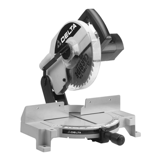
10" Power Miter Saw
(Model 36-070)
PART NO. 899880 (0012)
Copyright © 2000 Delta Machinery
ESPAÑOL: PÁGINA 21
To learn more about DELTA MACHINERY
visit our website at: www.deltamachinery.com.
For Parts, Service, Warranty or other Assistance,
1-800-223-7278 (
1-800-463-3582).
please call
In Canada call
Advertisement
Table of Contents

Related Manuals for Delta 36-070


Summary of Contents for Delta 36-070
- Page 1 10" Power Miter Saw (Model 36-070) PART NO. 899880 (0012) Copyright © 2000 Delta Machinery ESPAÑOL: PÁGINA 21 To learn more about DELTA MACHINERY visit our website at: www.deltamachinery.com. For Parts, Service, Warranty or other Assistance, 1-800-223-7278 ( 1-800-463-3582). please call...
-
Page 2: Safety Rules
If you have any questions relative to a particular applica- tion, DO NOT use the machine until you have first contacted Delta to determine if it can or should be performed on the product. -
Page 3: Additional Safety Rules For Miter Saws
32. THE USE of attachments and accessories not rec- 11. USE only blade flanges specified for your saw. ommended by Delta may result in the risk of injuries. 12. NEVER use blades larger or smaller in diameter than ten inches. -
Page 4: Assembly Instructions
UNPACKING 1. Remove the miter saw and all loose items from the carton. IMPORTANT: DO NOT LIFT THE MITER SAW BY THE SWITCH HANDLE AS THIS MAY CAUSE MIS- ALIGNMENT. ALWAYS LIFT THE MACHINE BY THE BASE OR CARRYING HANDLE. Fig. 2, illustrates the machine and all loose items after they have been removed from the carton. -
Page 5: Assembling Table Lock Handle
ASSEMBLING TABLE LOCK HANDLE 1. Thread table lock handle (A) Fig. 5, into the thread- ed hole (B) of the arm bracket. Fig. 5 ROTATING TABLE TO 90 DEGREE POSITION 1. Loosen table lock handle (A) Fig. 6, one or two turns and depress index lever (B) to release 45 degree positive stop. -
Page 6: Connecting Saw To Power Source
CONNECTING SAW TO POWER SOURCE POWER CONNECTIONS A separate electrical circuit should be used for your tools. This circuit should not be less than #12 wire and should be protected with a 20 Amp time lag fuse. If an extension cord is used, use only 3-wire extension cords which have 3- prong grounding type plugs and 3-pole receptacles which accept the tool’s plug. -
Page 7: Extension Cords
FOREWORD Delta Model 36-070 is a 10" Power Miter Saw designed to cut wood. Cross cutting and miter cutting are easy and accu- rate. It can crosscut up to 2-1/4" x 5-3/4", miter at 45 both left and right 2-1/4" x 4-1/8". It has positive miter stops at 0, 22.5, and 45 degrees both left and right, and is accurate to one half degree. -
Page 8: Starting And Stopping Machine
STARTING AND STOPPING MACHINE To start the machine, depress switch trigger (A) Fig. 12. To stop the machine, release the switch trigger. This miter saw is equipped with an automatic electric blade brake. As soon as the switch trigger (A) Fig. 12, is released, the electric brake is activated and stops the blade in seconds. -
Page 9: Locking Cuttinghead In Down Position
LOCKING CUTTINGHEAD IN THE DOWN POSITION When transporting the miter saw, the cuttinghead should always be locked in the down position. This can be accomplished by lowering the cuttinghead (A) Fig. 16, and pushing pin (B) until other end of pin (B) engages with hole in cutting arm. -
Page 10: Adjusting Blade Parallel To Table Opening
ADJUSTING BLADE PARALLEL TO TABLE OPENING 1. DISCONNECT THE SAW FROM THE POWER SOURCE. 2. Lower the cuttinghead and check to see if the saw blade (A) Fig. 20, is parallel to the left edge (B) of the table opening. 3. -
Page 11: Typical Operations And Helpful Hints
TYPICAL OPERATIONS AND HELPFUL HINTS 1. Before cutting, make certain the table is set at the correct angle and firmly locked in place. 2. Before cutting, determine that the workpiece is the right size for the saw. 3. Place the workpiece on the table and hold it firmly against the fence. 4. -
Page 12: General Cutting Operations
GENERAL CUTTING OPERATIONS 1. Your miter saw has the capacity to cut standard 2 x 4’s laying flat or on edge, at the 45 degree right and left Fig. 26 miter angles as shown in Figs. 26 and 27. Fig. 27 2. -
Page 13: Cutting Aluminum
4. Cutting various sizes of plastic pipe is an easy job with the miter saw, as shown in Fig. 30. CUTTING ALUMINUM Aluminum extrusions such as used for making aluminum screens and storm windows can easily be cut with your Fig. -
Page 14: Cutting Crown Mouldings
CUTTING CROWN MOULDINGS 1. There are several methods that can be used to cut crown mouldings on the miter saw. The method shown in Fig. 35, illustrates the contact surfaces (the surfaces that contact the wall and ceiling) of the crown moulding held firmly against the fence and table of the miter saw. - Page 15 5. Fasten the filler blocks to the fence using wood screws (A) through the two holes provided on each fence half, as shown in Fig. 40. This enables you to eas- ily remove the filler blocks when not in use and quickly reassemble them to the fence when needed.
-
Page 16: Changing The Blade
MAINTENANCE CHANGING THE BLADE WARNING: USE ONLY CROSS-CUTTING SAW BLADES. WHEN USING CARBIDE TIPPED BLADES, MAKE SURE THEY HAVE A NEGATIVE HOOK ANGLE. DO NOT USE BLADES WITH DEEP GULLETS AS THEY CAN DEFLECT AND CONTACT THE GUARD. USE ONLY 10" DIAMETER SAW BLADES WHICH ARE RATED FOR 6000 RPM OR HIGHER AND HAVE 5/8"... -
Page 17: Table Hazard Area
BRUSH INSPECTION AND REPLACEMENT CAUTION: BEFORE INSPECTING THE BRUSHES, DISCONNECT THE MACHINE FROM THE POWER SOURCE. Brush life varies. It depends on the load on the motor. Check the brushes after the first 50 hours of use for a new machine or after a new set of brushes has been installed. - Page 18 NOTES...
- Page 19 NOTES...
-
Page 20: Parts, Service Or Warranty Assistance
Two Year Limited Warranty Delta will repair or replace, at its expense and at its option, any Delta machine, machine part, or machine accessory which in normal use has proven to be defective in workmanship or material, provided that the customer returns the product pre- paid to a Delta factory service center or authorized service station with proof of purchase of the product within two years and provides Delta with reasonable opportunity to verify the alleged defect by inspection. - Page 21 Parts and accessories for Porter-Cable Delta products should be obtained by contacting any Porter-Cable Delta Distributor, Authorized Service Center, or Porter-Cable Delta Factory Service Center. If you do not have access to any of these, call 888-848-5175 and you will be directed to the nearest Porter-Cable Delta Factory Service Center.
Need help?
Do you have a question about the 36-070 and is the answer not in the manual?
Questions and answers