Table of Contents
Advertisement
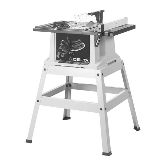
10" Motorized
Bench Saw
(Model 36-540 & Model 36-545 W/Stand)
PART NO. 899974-0010
Copyright © 2000 Delta Machinery
To learn more about DELTA MACHINERY
ESPAÑOL: PÁGINA 23
visit our website at: www.deltamachinery.com.
For Parts, Service, Warranty or other Assistance,
1-888-848-5175 (
1-800-463-3582).
please call
In Canada call
Advertisement
Chapters
Table of Contents

Related Manuals for Delta 36-540


Summary of Contents for Delta 36-540
- Page 1 10" Motorized Bench Saw (Model 36-540 & Model 36-545 W/Stand) PART NO. 899974-0010 Copyright © 2000 Delta Machinery To learn more about DELTA MACHINERY ESPAÑOL: PÁGINA 23 visit our website at: www.deltamachinery.com. For Parts, Service, Warranty or other Assistance, 1-888-848-5175 ( 1-800-463-3582).
-
Page 2: Safety Rules
If you have any questions rela- tive to a particular application, DO NOT use the machine until you have first contacted Delta to determine if it can or should be performed on the product. -
Page 3: Additional Safety Rules For Circular Saws
E. Not ripping work that is twisted or warped or 25. THE USE of attachments and accessories not rec- does not have a straight edge to guide along ommended by Delta may result in the risk of injuries. the fence. 26. ADDITIONAL INFORMATION regarding the safe 10. - Page 4 UNPACKING Your new saw is shipped complete in one container. Carefully unpack the saw and all loose items from the shipping container. Fig. 2, illustrates the saw removed from the container and Fig. 2A, illustrates all the loose items packed with the saw. Fig.
- Page 5 Fig. 4 30 - Leg (4) 31 - 3/8” Flat Washer for Mounting Saw to Stand & for Assembling Stand (24) 32 - Foot (4) 33 - M8 Hex Nut for Mounting Saw to Stand & for Assembling Stand (20) 34 - M8 x 40mm Hex Screw for Mounting Saw to Stand (4) 35 - M8 x 20mm Carriage Bolts for Assembling Stand (16) 36 - 18-1/2”...
-
Page 6: Assembling Blade Raising And Lowering Handwheel
ASSEMBLY INSTRUCTIONS ASSEMBLING BLADE RAISING AND LOWERING HANDWHEEL Insert M6 x 55 screw (9) Fig. 2A, through handle (E) Fig. 3A, and assemble handle (E) to handwheel (A) by threading screw (D) clockwise into handwheel. Fig. 3A 2. Fig. 3B, illustrates the handle (E) assembled to hand- wheel (A). - Page 7 ASSEMBLING BLADE GUARD AND SPLIT- TER ASSEMBLY 1. DISCONNECT THE SAW FROM THE POWER SOURCE. 2. IMPORTANT: THE BLADE GUARD AND SPLITTER ASSEMBLY MUST BE PROPERLY ALIGNED TO THE SAW BLADE IN ORDER TO PREVENT KICKBACK. 3. Position the blade 90 degrees to the table and lock in place.
- Page 8 8. Assemble splitter (H) Fig. 11, to splitter support bracket (B) as shown using 3/4 inch-long hex head screw, external tooth washer, and flat washer (L). 9. Fasten splitter (H) Fig. 12, to splitter support bracket using flat washer, external tooth lockwasher and wing Fig.
- Page 9 ASSEMBLING MITER GAGE HOLDER 1. DISCONNECT THE SAW FROM THE POWER SOURCE. 2. Assemble spring clip (E) Fig. 13A, to the miter gage holder (A) as shown using 10mm pan head screw (F), lockwasher and hex nut. NOTE: Hex nut (G) Fig. 13B, will fit into the recess at the back of the miter gage holder (A) to keep spring clip (E) Fig.
-
Page 10: Assembling Rip Fence
ASSEMBLING RIP FENCE 1. Thread locknut (A) Fig. 17, approximately halfway onto stud of handle (B). 2. Thread handle (B) Fig. 17, into tapped hole (C) in fence cam (D). Tighten locknut (A) Fig. 18, against cam (D). 3. The rip fence is usually operated on the right hand side of the saw table. -
Page 11: Top Front And Rear
ASSEMBLING STAND 1. Assemble the stand as shown in Fig. 20A, using 32 carriage bolts, flat washers and hex nuts. Do not com- pletely tighten the hardware at this time. Letters are stamped on the stand brackets for ease in assembly. A - Top front and rear brackets B - Top side brackets C - Bottom side brackets... -
Page 12: Connecting Saw To Power Source
CONNECTING SAW TO POWER SOURCE POWER CONNECTIONS A separate electrical circuit should be used for your tools. This circuit should not be less than #12 wire and should be protected with a 20 amp fuse. Have a certified electrician replace or repair a worn cord immediately. -
Page 13: Overload Protection
EXTENSION CORDS MINIMUM GAUGE EXTENSION CORD Ampere Volts Total Length of Gage of Use proper extension cords. Make sure your extension Rating Cord in Feet Extension Cord cord is in good condition and is a 3-wire extension cord up to 25 18 AWG which has a 3-prong grounding type plug and a 3-pole 16 AWG... -
Page 14: Blade Tilting Control
BLADE RAISING AND LOWERING CONTROL To raise or lower the saw blade, turn handwheel (A) Fig. 26. Turning the handwheel clockwise lowers the blade and turning the handwheel counterclockwise raises the blade. WARNING: THE BLADE TILTING LOCK HAN- DLE (B) FIG. 26, MUST BE LOCKED DURING ALL CUTTING OPERATIONS. - Page 15 RIP FENCE OPERATION AND ADJUSTMENTS 1. To move the rip fence (A) Fig. 30, along the table, lift up fence locking lever (B), slide the fence to the desired location on the table and push down fence locking lever (B) to lock the fence in position. 2.
-
Page 16: Changing The Blade
ADJUSTING BLADE PARALLEL TO MITER GAGE SLOTS The blade was adjusted parallel to the miter gage slots at the factory. In order to insure accurate cuts and help pre- vent kickback when cutting, this adjustment should be rechecked and if necessary, readjusted as follows: 1. - Page 17 The following information describes the safe and proper method for per- forming the most common sawing operations. Additional information on table saw operations can be obtained from the Delta “Getting the Most Out of Your Table Saw” How-To-Book, Catalog No. 11-400.
- Page 18 RIPPING Ripping is the operation of making a length-wise cut through a board, as shown in Fig. 37, and the rip fence (A) is used to position and guide the work. One edge of the work rides against the rip fence while the flat side of the board rests on the table.
-
Page 19: Constructing A Featherboard
Fig. 40 Further information on the safe and proper operation of table saws is available in the Delta “Getting the Most Out of Your Table Saw” How-To-Book, Catalog No. 11-400. Additional information on table saw safety is also avail-... -
Page 20: Constructing A Push Stick
CONSTRUCTING A PUSH STICK When ripping work less than 4 inches wide, a push stick should be used to complete the feed and could easily be made from scrap material by following the pattern shown in Fig. 42. - Page 21 NOTES...
- Page 22 PARTS, SERVICE OR WARRANTY ASSISTANCE All Delta Machines and accessories are manufactured to high quality standards and are serviced by a network of Porter- Cable • Delta Factory Service Centers and Delta Authorized Service Stations. To obtain additional information regarding your Delta quality product or to obtain parts, service, warranty assistance, or the location of the nearest service outlet, please call 1-888-848-5175, (In Canada call 1-800-463-3582).
Need help?
Do you have a question about the 36-540 and is the answer not in the manual?
Questions and answers