Table of Contents
Advertisement
Quick Links
Owner's Manual
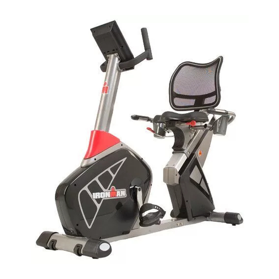
Transition Recumbent Bike
Customer Service
(800) 750-4766
Manufactured By:
Ironman Fitness
4009 Distribution Drive
Suite 250
Garland, TX 75041
CAUTION
Read all precautions and instructions in
this manual before using this equipment.
Model Name : TRANSITION
Serial Number :
Serial Number can be found at
the above specified location.
315-00137
09/17 Rev 5.0
Advertisement
Table of Contents

Related Manuals for Ironman Fitness Transition Recumbent Bike IM-R7


Summary of Contents for Ironman Fitness Transition Recumbent Bike IM-R7
- Page 1 Owner’s Manual Transition Recumbent Bike Customer Service (800) 750-4766 Manufactured By: Ironman Fitness 4009 Distribution Drive Suite 250 Garland, TX 75041 CAUTION Read all precautions and instructions in this manual before using this equipment. Model Name : TRANSITION Serial Number : Serial Number can be found at the above specified location.
-
Page 2: Table Of Contents
This manual will guide you through the assembly process. If at any time you are having trouble with the assembly or use of this product, then please contact us at our Ironman Fitness Help line. We have trained service technicians on site to take care of you, our valued customer. -
Page 3: Important Safety Information
35 years, do not use the pre-set programs or start an exercise program without first contacting and receiving approval from your physician. To avoid the risk of electrical shock, always keep the console dry. Do not spill liquids on the console. Ironman Fitness recommends a sealed water bottle for beverages consumed while using the unit. -
Page 4: Assembly
Assembly www.ironmanfitness.com... -
Page 5: Parts Identifier
Rear Main Frame Upright Post Prior to assembly, remove components from the box and verify that all the listed parts were supplied. Front Main Frame Console Upright Handlebar www.ironmanfitness.com Front Seat Slide Stabilizer Adjustment Handle Rear Stabilizer Seat Pad Back Rest Parts Identifier... - Page 6 www.ironmanfitness.com Upright Post Cover Adapter Allen Screws M8*15 Allen Screws M6*12 Allen Screws 1/4” *40 Oval Washers 8*4.5 Flat Washers (Black) M8 Important Information Parts Identifier Side Handlebar - Left Side Handlebar - Right Spring Washers M8 Allen Screws M8*20 Accessory Tray - Right Accessory Tray - Left Water Bottle...
-
Page 7: Assembly Steps
www.ironmanfitness.com ASSEMBLY FOR FRONT STABILIZER Secure the front stabilizer (B) to the front main frame (A1) using 2 screws (N7), 2 spring washers (N2) and 2 flat washers (N3). Note: Front stabilizer (B) is very similar to rear stabilizer (C) but contains transport wheels. Make sure not to get them mixed up. - Page 8 www.ironmanfitness.com ASSEMBLY FOR REAR STABILIZER Secure the rear stabilizer (C) to the rear main frame (A2) using two screws (N4), 2 spring washers (N2) and 2 flat washers (N3). Note: After you finish the assembly for front and rear stabilizer bars in order to add stability to the unit, you may need to adjust the levelers that are located on the bottom of the unit.
- Page 9 www.ironmanfitness.com Use Tool ASSEMBLY FOR FRONT & REAR MAIN FRAME Step 1: Connect the front (A4) and rear (A3) pulse wires together. Step 2: Attach front (A1) and rear (A2) main frames together, mak- ing sure all wires are lined up correctly so that they are not pinched when assembling the two frames together.
- Page 10 www.ironmanfitness.com ASSEMBLY FOR UPRIGHT POST Step 1: Insert the upright post cover (I) to the upright post (D) from the bottom side. Step 2: Connect the lower pulse wire (A4) with the upper pulse wire (A33). Also, connect the lower sensor wire (A36) with the upper sensor wire (A34).
- Page 11 Use Tool Use Tool www.ironmanfitness.com ASSEMBLY FOR SEAT SLIDE ADJUSTMENT Insert the seat slide adjustment handle (A11) into the seat slide adjsutment collar on the seat slide assem- bly (A9). Secure it with M6 set screw (N10). ASSEMBLY FOR RIGHT HANDLEBAR Step 1: Connect pulse wire (J1) and pulse wire (A3).
- Page 12 www.ironmanfitness.com J-(L) ASSEMBLY FOR SEAT CUSHION Attach seat (G) to the seat slide assembly (A9) using allen screws (N1) and flat washers (N3). ASSEMBLY FOR LEFT HANDLEBAR Use Tool Step 1: Connect pulse wire (J2) and pulse wire (A3). Step 2: Mount the right handlebar (J-l), to the seat slide as- sembly (A9) and secure with 3 allen screws (N6).
- Page 13 www.ironmanfitness.com Use Tool J-(L) ASSEMBLY FOR BACK REST Step 1: J-(R) Attach the back rest (H) to the seat support tube (A10) and secure it using 4 allen screws (N5). ASSEMBLY FOR ACCESSORY TRAYS Step 1: Attach the right accessory tray (R2) to the side handlebar - right (J-R) and secure using 3 screws (N8) and 3 oval washers (N12).
- Page 14 www.ironmanfitness.com ASSEMBLY FOR UPRIGHT HANDLEBAR Attach the handlebar (e) to the upright post (D) and secure it with 2 allen screws (N9) and 2 flat washers (N11). Use Tool 14 Assembly Important Information...
- Page 15 Use Tool www.ironmanfitness.com ASSEMBLY FOR CONSOLE Step 1: Connect the sensor wire (A34) and the pulse wire (A33) with the corresponding wires on the console (F). Step 2: Gently push all wires into the upright post and mount the console (F) onto the console mounting plate at the top of the upright tube (D).
- Page 16 www.ironmanfitness.com Use Tool 15mm 13mm ASSEMBLY FOR PEDALS L-(L) L-(L) Step 1: COUNTER-CLOCKWISE L-(R) Attach left pedal strap (l1) to left pedal (l-l) and right pedal strap (l2) to right pedal (l-R). Step 2: CLOCKWISE Thread the left pedal (l-l) into the L-(R) pedal crankshaft in the counter- clockwise direction.
- Page 17 www.ironmanfitness.com Congratulations! You have completed the assembly of your new Ironman Transition Recumbent Bike! Important Information Assembly...
- Page 18 www.ironmanfitness.com ADJUSTING YOUR BACK REST POSITION Assembly...
- Page 19 www.ironmanfitness.com ADJUSTING YOUR SEAT POSITION PULL UP LOCK PULL DOWN RELEASE Important Information Assembly...
- Page 20 www.ironmanfitness.com ADAPTER PLUG-IN LOCATION Adapter (M) TRANSPORTING YOUR UNIT TRANSPORT WHEELS Important Information Assembly...
-
Page 21: Console Information
Console Information www.ironmanfitness.com... -
Page 22: Console Buttons
CONSOLE BUTTONS: UP/DOWN: These buttons are used to change programs and settings. ENTER: This button is used as an entry key, which will allow user to confirm settings such as time, distance and calories. RECOVERY: This button is used to begin the Recovery feature of the console (refer to Console Function section for more information). -
Page 23: Console Functions
www.ironmanfitness.com CONSOLE FUNCTIONS: TIME: If a target time was not selected, time will count up from 00:00 to maximum 99:59. When working out with a target time, time will count down from target to 00:00. When selecting target time, use the +/- buttons, the time will change in 1 minute increments and can range from 1:00 min to 99:00 mins. -
Page 24: General Information
www.ironmanfitness.com RECOVERY: After your workout, keep holding on hand grips and press “ReCoVeRY” button. All function display will stop except “TIMe” starts counting down from 00:60 to 00:00. Screen will display your heart rate recovery status rating between F1-F6. F1 is the best, F6 is the worst. -
Page 25: Preset Programs
buttons. PRESET PROGRAMS: each Program is divided into ten segments. Use the UP/DoWN buttons to scroll to this program. Press MoDe/eNTeR to select this program. TIMe will flash in the display. Use the UP/DoWN keys to set desired TIMe. Press MoDe/eNTeR to confirm value. -
Page 26: Monitoring Your Heart Rate
www.ironmanfitness.com MONITORING YOUR HEART RATE: To obtain the greatest cardiovascular benefits from your exercise workout, it is important to work within your target heart rate zone. The American Heart Association (AHA) defines this target as 60%-75% percent of your maximum heart rate. Your maximum heart rate may be roughly calculated by subtracting your age from 220. -
Page 27: Target Heart Rate Zone
Fitness Safety - The Heart Rate chart indicates average rate for you. Your physician or health care professional can help you determine the exercise intensity that is appropriate for your age and condition. www.ironmanfitness.com TARGET HEART RATE ZONE 100% Serious athletic training range Cardiovascular... -
Page 28: Workout Information
Workout Information www.ironmanfitness.com Important Information... -
Page 29: Exercise Guidelines
Prone on Elbows Lie on your stomach with your feet together. Rest on your forearms with your elbows directly under your sholdres. Relax lower back and abdomen into the floor. Hold for 30-60 seconds or until muscles feel looser Cat and Camel Rest on your hands and knees. - Page 30 www.ironmanfitness.com Wrist Extensor Extend your right arm in front of you with your palm up and your elbow straight. Point your fingertips toward the floor by bending at the wrist. Using your left hand, pull the back of your right hand toward you gently.
-
Page 31: Calf Stretch
Calf Stretch Face a solid structure such as a wall with your left foot ahead of your right, toes straight ahead. Bend your left knee, press your hips forward, and lean into the wall. Keep both heels down, your right leg straight, and you left knee over your ankle. -
Page 32: Parts Information
Parts Information www.ironmanfitness.com Important Information... -
Page 33: Exploded View
www.ironmanfitness.com Important Information Exploded View... - Page 34 www.ironmanfitness.com Ref # MAIN FRAMe, FRoNT A1-1 NUT, M8 A1-2 SCReW, M8X52 MAIN FRAMe, ReAR A2-1 BTN HD AlleN BolT, M8X10 A2-2 TRACK, AlUMINUM A2-3 SToPPeR, CeNTeR A2-4 SCReW, M4X10 A2-5 SCReW, M4X12 A2-6 SToPPeR, leFT BlACK A2-7 SToPPeR, RIGHT BlACK WIRe HARNeSS, eKG ReAR WIRe HARNeSS, eKG MIDDle NUT, 3/8X26X7mm...
-
Page 35: Warranty Information
Missing/Cosmetic Parts: 30 Days Limited Warranty This Limited Warranty applies in the United States and Canada to Products manufactured or distributed by IRONMAN Fitness under the IRONMAN Fitness (“IRONMAN”) brand name (as used herein, the “Product” or “Products”). The warranty period to the original purchaser is listed above, and commences on the date of original purchase of the product, unless otherwise autho- rized by IRONMAN. - Page 36 Ironman Fitness 4009 Distribution Drive, Suite 250 Garland, Texas 75041 Customer Service: 1-800-750-4766 IRONMAN, IRONMAN TRIATHLON and M-DOT are registered trademarks of World Triathlon Corporation. This product is licensed by the IRONMAN TRIATHLON. Important Information...
Need help?
Do you have a question about the Transition Recumbent Bike IM-R7 and is the answer not in the manual?
Questions and answers