Advertisement
Quick Links
Instructions for use
Thank you for purchasing the Musical Fidelity M1 PWR.
The M1 PWR consists of a top quality Class-D switch-mode power amplifier circuit giving exceptional performance
into virtually any speakers. It features efficient switching technology with zero crossover distortion artefacts and with
just the right amount of feedback to give the best sound quality possible. It may also be used in a monoblock mode
(with a matching amplifier for the other channel) in which the power output is considerably increased. It is
complemented with a generous universal voltage power supply circuit, allowing astounding imaging, detail and
transparency, to deliver all music types exactly as the artist originally intended. A line (loop) output allows for further
or future expansion.
The M1 PWR has been carefully designed to be partnered with M1 series, and also matches well with M3 and M6
series products. These combinations will yield one of the best high-fidelity systems available at any price.
Used carefully, it should give many years of outstanding musical reproduction.
Dust regularly with a soft duster or soft brush, but be careful when using cleaning or polishing agents - they may
harm the surface finish.
If there are any questions about the audio system, please consult the dealer who is there to help and advise.
Advertisement

Related Manuals for Musical Fidelity M1PWR


Summary of Contents for Musical Fidelity M1PWR
- Page 1 Instructions for use Thank you for purchasing the Musical Fidelity M1 PWR. The M1 PWR consists of a top quality Class-D switch-mode power amplifier circuit giving exceptional performance into virtually any speakers. It features efficient switching technology with zero crossover distortion artefacts and with just the right amount of feedback to give the best sound quality possible.
- Page 2 CONTENTS Section Page – Mains plug (UK only), modification warning Safety Information – Installation precautions General advice – EU disposal information Disposal information – Introduction, cleaning, installation, power connections, audio Installation connections – Illustrations - main unit front & rear panels Facilities and connections –...
-
Page 3: Safety Information
• If connecting to a BS1363 plug, a 13 amp fuse must be used. WARNING: MODIFICATIONS THIS PRODUCT EXPRESSLY APPROVED BY MUSICAL FIDELITY WHO IS THE PARTY RESPONSIBLE STANDARDS COMPLIANCE COULD VOID USER'S AUTHORITY TO OPERATE THIS EQUIPMENT. Issue 2... -
Page 4: General Advice
Do not remove any covers or try to gain access to the inside. There are no user adjustments or fuses to change without qualification. Refer all service work to an authorised Musical Fidelity agent. * Note: Unauthorised opening of the equipment will invalidate any warranty claim. -
Page 5: Item Disposal Information
ITEM DISPOSAL INFORMATION DISPOSAL The crossed out wheeled bin label that appears on the back panel of the product indicates that the product must not be disposed of as normal household waste. To prevent possible harm to the environment please separate the product from other waste to ensure that it can be recycled in an environmentally safe manner. - Page 6 Please note: Musical Fidelity currently do not make any interconnecting cables, nor do we endorse any particular manufacturer’s cables. If necessary, please refer the dealer who can advise on quality cables for any particular setup.
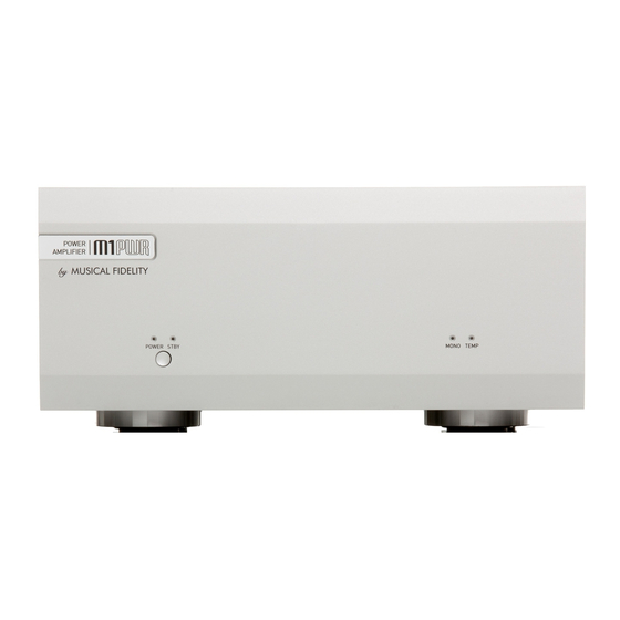
- Page 7 FACILITIES & CONNECTIONS POWER Blue power-on LED. MONO Blue LED indicates MONO mode. POWER/STBY button TEMP Red LED indicates internal overheating. STBY Orange standby LED 11 LINE INPUTS right and left TRIGGER IN 3.5mm jack socket 12 LOOP OUTPUTS right and left TRIGGER OUT 3.5mm jack socket 13 IEC MAINS INPUT STEREO/MONO mode switch...
- Page 8 OPERATION Switching on. When first connected to a mains supply the orange STDBY LED should light. This indicates the unit is in low power standby mode and that mains power is connected. (if it is not on, check mains wall socket switch is on, if present.) To turn the unit on, press the POWER STBY button once.
- Page 9 OPERATION Setup (Mono “block” mode) Two units, are hereby required for a stereo setup; one designated for the “left” channel; the other for the “right” channel. Speaker connections Make sure the unit is switched OFF. Check the switch on back panel is in MONO position. Connect the left hand speaker wires to the LEFT SPEAKER OUTPUT binding posts of the left hand M1 PWR unit.
- Page 10 OPERATION Bi-wiring (in monoblock mode only) It is possible to take advantage of the above feature to “bi-wire” the outputs to suitable speakers. Such speakers must have at least four terminals; two for the treble, high frequency (or HF) driver and two more for the bass, low frequency (or LF) driver.
- Page 11 Check connections and make sure level output they are secure. If none of these actions affect a cure, please contact the dealer, or an authorised Musical Fidelity service agent. Never open the case of the unit, as this will invalidate the guarantee. Issue 2...
-
Page 12: Specifications
(4”) Deep, including terminals 315 mm (12½”) Standard accessories IEC type mains lead (10-Amp type) Musical Fidelity reserves the right to make improvements which may result in specification or feature changes without notice. E&OE. Issue 2 Page 12 of 13... - Page 13 MANUAL HISTORY RELEASE DATE CHANGES Issue 1 Dec 14 2011 issue. Issue 2 February 2012 Fault LEDs clarified Issue 2 Page 13 of 13...
Need help?
Do you have a question about the M1PWR and is the answer not in the manual?
Questions and answers