IDS X64 User Manual
Ids x64 is a versatile 8-zone alarm panel with 8 partitions
Hide thumbs
Also See for X64:
- Installer manual (96 pages) ,
- Quick programming manual (37 pages) ,
- User manual (32 pages)
Table of Contents
Advertisement
Quick Links
Advertisement
Table of Contents

Related Manuals for IDS X64


Summary of Contents for IDS X64
- Page 1 IDS X64 User Manual 700-398-01D Issued August 2010...
- Page 2 IDS X64 User Manual 700-398-01D Issued August 2010...
-
Page 3: Table Of Contents
Contents Introduction to the IDS X64 ..................... 7 Before Operating Your Alarm System ................7 Understanding the Keypad LEDs ................... 8 Viewing Data on an LED Keypad ................... 12 3.1.1 LED Status Indicators ......................12 3.1.2 Numerical Values ........................12 3.1.3... - Page 4 Peripheral Communications Failure ..................36 16.1.11 Peripheral Low Supply Voltage ....................36 16.1.12 EEPROM Chip Failure ......................36 Changing a Partition ..................... 37 Output Control via a Keypad ..................37 Maintenance Code - Advanced ..................37 IDS X64 User Manual 700-398-01D Issued August 2010...
- Page 5 Table 10: Output Address Physical Mapping Data ................ 28 Table 11: Output Actions Data ......................29 Table 12: Enable User Reporting Codes ..................29 Table 13: Specify which Telephone Module to use................ 30 Table 14: Trouble Conditions ......................35 IDS X64 User Manual 700-398-01D Issued August 2010...
- Page 6 Stay Arm and Go Arming that allows the user to Stay arm and leave the premises. Stay Zone A zone that is bypassed automatically when the system is Stay armed. IDS X64 User Manual 700-398-01D Issued August 2010...
-
Page 7: Introduction To The Ids X64
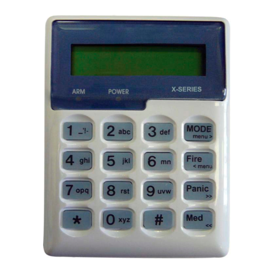
Congratulations on your purchase of an IDS Alarm Panel to protect your most valued possessions. The IDS X64 is a versatile 8-zone alarm panel with 8 partitions and can be expanded to monitor 64 zones. Most features are optional and may be programmed directly through the keypad. There is a dedicated panic zone, monitored siren output, auxiliary power outputs and 5 (expandable to 25) programmable outputs that may be programmed to perform various trigger/switching functions. -
Page 8: Understanding The Keypad Leds
Section: 3 Understanding the Keypad LEDs IDS X64 User Manual 700-398-01D Issued August 2010... - Page 9 Section: 3 IDS X64 User Manual 700-398-01D Issued August 2010...
- Page 10 Section: 3 IDS X64 User Manual 700-398-01D Issued August 2010...
- Page 11 Section: 3 IDS X64 User Manual 700-398-01D Issued August 2010...
-
Page 12: Viewing Data On An Led Keypad
Each zone LED directly corresponds to a number of the same value. For numbers or information that exceeds a value of 16, binary-coded decimal values are used, as explained in the following sections. IDS X64 User Manual 700-398-01D Issued August 2010... -
Page 13: Reading Binary Values
Data is easily entered on a keypad. Below is a list of keys and their functions. [*] – This key is used as an enter key, to confirm the data that you have inputted. It is also used to scroll to the next sub-location. IDS X64 User Manual 700-398-01D Issued August 2010... -
Page 14: The Keypad Buzzer
Enter a valid [USER CODE]. If an incorrect code is entered, the keypad buzzer will beep three times. In the event of an error press the [#] key and re-enter the code. IDS X64 User Manual 700-398-01D Issued August 2010... -
Page 15: Quick Away Arm
Enter a valid [USER CODE]. If an incorrect code is entered, the keypad will give an error beep. In the event of an error press the [#] key and re-enter the [USER CODE]. IDS X64 User Manual 700-398-01D Issued August 2010... -
Page 16: Quick Stay Arm
Ensure that the READY LED is on before leaving. Leave the premises and lock the door. Activate the remote or the key-switch. (A remote can be used to Away Arm.) The panel will arm in the away mode. IDS X64 User Manual 700-398-01D Issued August 2010... -
Page 17: Auto Arm
Entering a valid user code will cancel the strobe. How to Disarm Using a Key-switch or Remote Activate the remote or key-switch. (The blue button on the IDS remote, unless otherwise programmed). -
Page 18: Bypassing/Un-Bypassing A Zone
The siren will sound on and off repeatedly if programmed and the FIRE REPORTING CODE will be transmitted to the monitoring company. To silence the siren enter a valid [USER CODE]. IDS X64 User Manual 700-398-01D Issued August 2010... -
Page 19: Panic
Zone LEDs that are on show which zones were violated during the last armed period. Press the [1] key followed by the [*] key to return to violated zones. Press the [2] key followed by the [*] key to display zones that were bypassed. IDS X64 User Manual 700-398-01D Issued August 2010... -
Page 20: Event Log
The first number is the partition number within which the event occurred. The second number will either be the zone or user number associated with the event type. Below is an example of how an event will be displayed on the two-line IDS LCD keypad. “02:00 01/01/2010”... -
Page 21: User Program Options
Section: 10 User Program Options The IDS X64 Alarm Panel has 128 programmable user codes. By default, user code 1 is the Master User Code that contains a pre-programmed 4-digit code of 1234. NOTE: User codes may be 4 (default) or 6 digits long (with a default code of 123456). This is a programmable feature. -
Page 22: System Time And Date Options
Further codes may be added by repeating step 4. Press the [#] key to exit the current option. Press the [OPTION NUMBER] followed by the [*] key for the next option, or the [#] key again to exit user programming. IDS X64 User Manual 700-398-01D Issued August 2010... -
Page 23: Edit A Selected User Code - Option 1
The READY and AWAY LEDs flash simultaneously, and the ARM LED is on. Enter the [USER CODE] followed by the [*] key. The READY and ARM LEDs flash simultaneously. Further slots may be added/edited by repeating steps 4 - 7. IDS X64 User Manual 700-398-01D Issued August 2010... -
Page 24: Delete A User Code - Option 4 (Slot Known)
NOTE: A slot is just a place holder number for a user code. I.e. User code 1 is in slot 1; all the way to user code 128 is in slot 128. IDS X64 User Manual 700-398-01D Issued August 2010... -
Page 25: User Code Properties - Option 10
This is a special 4 (default) or 6-digit user code (check the code length with your installer) and should only be used in the unique situation where an intruder forces one to disarm the system "under duress". IDS X64 User Manual 700-398-01D Issued August 2010... -
Page 26: Arm To Disarm Code [Maid's Code]
1 to 5 will use the panel’s onboard outputs 1 to 5. Assigning an event to outputs 6 to17 will use an output on a zone expander, 18-33 are reserved, and 34-41 will use an output on a keypad. Refer to section 12.9 for details on using programmable outputs. IDS X64 User Manual 700-398-01D Issued August 2010... -
Page 27: Assign A User Code To Partitions - Option 11 (Advanced)
Repeat steps 4 - 9 until all the user outputs you want have been entered. Press the [#] key to exit the current option. Press the [OPTION NUMBER] followed by the [*] key for the next option, or the [#] key again to exit user programming. IDS X64 User Manual 700-398-01D Issued August 2010... -
Page 28: Table 9: An Example On How To Read User Outputs On An Led Keypad
Zone expander 5 output 2 Keypad 3 output Zone expander 6 output 1 Keypad 4 output Zone expander 6 output 2 Keypad 5 output Reserved Keypad 6 output Reserved Keypad 7 output Reserved Keypad 8 output IDS X64 User Manual 700-398-01D Issued August 2010... -
Page 29: User Reporting Codes Enable - Option 14 (Advanced)
Enter the [USER CODE] followed by the [*] key. The READY and AWAY LEDs flash simultaneously, and the ARM LED will be on. Enter the [BITMAP] that you want followed by the [*] key. IDS X64 User Manual 700-398-01D Issued August 2010... -
Page 30: Remote Receiver - Options 20 - 29 (Advanced)
1 and 2. 12.12 Remote Receiver – Options 20 – 29 (Advanced) Refer to the X64 Remote Receiver Manual for the available user options that can be programmed. 12.13 LCD Keypad – Option 30 (Advanced) Refer to the X64 LCD Keypad Manual for the available user option that can be programmed. -
Page 31: Edit The Date - Option 41
Press the [5] key and then simultaneously press keys [1], [2], [3], or [4] – depending on the stay profile you want to choose – then release both keys. A beep will sound to indicate successful selection of a profile (an LCD keypad will also display the profile number). IDS X64 User Manual 700-398-01D Issued August 2010... -
Page 32: How To Program Stay Zones
If a valid user code is not entered during this period, the system will register an alarm condition. This feature helps prevent unnecessary false alarms. IDS X64 User Manual 700-398-01D Issued August 2010... -
Page 33: How To Program A Buzz Zone
If you wish to know each time someone enters or exits the front door of your office, program this zone as a chime zone. The keypad will beep each time someone opens the front door. IDS X64 User Manual 700-398-01D Issued August 2010... -
Page 34: How To Program Chime Zones
[7] key for 2 seconds, and then press the [#] key to clear. To cancel the beeping without viewing the trouble conditions, press the [#] key. IDS X64 User Manual 700-398-01D Issued August 2010... -
Page 35: Explanation Of Trouble Conditions
This trouble condition can be caused by a low battery voltage, a dead battery, or no battery. If the battery is there, try charging it. If this not does work, then you may have to buy a new battery. A battery is an IDS X64 User Manual 700-398-01D Issued August 2010... -
Page 36: Aux 12V Resettable Fuse Blown
Supply voltage to a peripheral has dropped below the recommended limit. Contact your installer. 16.1.12 EEPROM Chip Failure The panel is not communicating correctly due to a serious error. Contact your installer immediately. IDS X64 User Manual 700-398-01D Issued August 2010... -
Page 37: Changing A Partition
The default maintenance code is 8888, or 888888 for a 6-digit code. Contact your installer to change this if you so desire. This code is used to maintain the following locations: Locations 17-18: Siren Time and Delay IDS X64 User Manual 700-398-01D Issued August 2010... -
Page 38: Ids X64 User Manual 700-398-01D Issued August
Daylight Savings Locations 171-173: No Movement, Auto Arm Locations 174-176: No Movement, Alarm Locations 180-190: Auto Arm Times NOTE: If you want to use the maintenance code, please contact your installer for assistance. IDS X64 User Manual 700-398-01D Issued August 2010... - Page 39 Maid’s Code ....................................25 Master User Code ................................21, 25 Medical ..................................... 6, 19, 41 Panic ................................6, 7, 18, 19, 32, 34 Partition ............................. 6, 15, 16, 20, 26, 27, 31, 37 IDS X64 User Manual 700-398-01D Issued August 2010...
- Page 40 Tamper ..................................... 6, 35, 36 Testing......................................7 Trouble Condition ................................34, 35, 43 User Code ..................................21, 23, 24 Zone Buzz ....................................31, 32 Entry/Exit..................................6, 16, 33 Follower ....................................6 Instant .....................................6 Stay ..................................31, 32, 33 IDS X64 User Manual 700-398-01D Issued August 2010...
- Page 41 READY on User Menu READY and ARM flashing alternately [MODE] Mode READY flashing Medical Entering User Option Program m Mode [MASTER CODE] [*] READY flashes [USER OPTION] [*] READY and ARM flashes IDS X64 User Manual 700-398-01D Issued August 2010...
- Page 42 Edit the Time [*] [Master Code] [*] [4] [0] [*] [Time] [*] Edit the Date [*] [Master Code] [*] [4] [1] [*] [Date] [*] Change Partitions [Mode] [1] [*] [Partition Number] [*] IDS X64 User Manual 700-398-01D Issued August 2010...
- Page 43 10 = Comms Loss to Peripheral Device 11 = Loss of Power to Peripheral Device 12 = EEPROM Failure NOTE: The first key pressed in any programming sequence needs to be held down until the beep is heard. IDS X64 User Manual 700-398-01D Issued August 2010...
- Page 44 IDS X64 User Manual 700-398-01D Issued August 2010...
Need help?
Do you have a question about the X64 and is the answer not in the manual?
Questions and answers