
Related Manuals for Husqvarna HUV4421D


Summary of Contents for Husqvarna HUV4421D
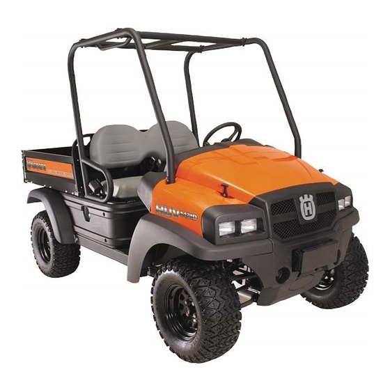
- Page 1 2007 Utility Vehicles Gasoline and Diesel Owner’s Manual HUV 4421G HUV 4421GXP HUV 4421D HUV 4421DXP...
- Page 3 Your authorized representative checked the vehicle before it was delivered to you and will provide you a copy of the completed vehicle warranty registration form. Husqvarna is not liable for errors in this manual or for incidental or consequential damages that result from the use of the material in this manual.
- Page 4 Husqvarna representative perform them. For the name and address of the Husqvarna representative nearest you, logon to our web site at www.usa.husqvarna.com. If you would prefer to write to us, direct your letter to: Husqvarna, Attention: Marketing Services, 7349 Statesville Rd., Charlotte, NC 28269 USA. Your local autho- rized Husqvarna representative can also provide technical advice, parts, and service manuals.
-
Page 5: Table Of Contents
TABLE OF CONTENTS Safety Details ... General Warnings ... General Information ... 10 Model Identification ... 10 Controls and Indicators ... 10 Roll-Over Protective Structure and Safety Belts ... 15 Seat Latch and Adjustment ... 17 Pre-Operation and Daily Safety Checklist ... 17 Performance Inspection ... - Page 6 Vehicle Feature Identification ALL HUV 4421 MODELS DIESEL WARNING DECAL (DIESEL VEHICLES ONLY, GASOLINE WARNING DECAL ON PASSENGER-SIDE SEAT SUPPORT) (GASOLINE VEHICLES ONLY, ON PASSENGER-SIDE SEAT SUPPORT) OPERATING INSTRUCTIONS (ON INSTRUMENT PANEL) HOT MANIFOLD WARNING DECAL (ON ENGINE VALVE COVER) WINCH CABLE WARNING DECAL (FOR VEHICLES WITH WINCH ACCESSORY) FRAME GROUND WARNING DECAL...
-
Page 7: Vehicle Feature Identification
ALL HUV 4421 MODELS DRIVER/PASSENGER WARNING DECAL ROTATING PARTS DECAL - DIESEL (UNDER SEAT ON DRIVER-SIDE FRAME) SERIAL NUMBER DECAL CRUSH AREA DECAL (ON DRIVER SIDE AND PASSENGER SIDE) VEHICLE LOADING DECAL (STANDARD VEHICLE) (HIGH-CAPACITY OPTION) 2007 HUV 4421 Gasoline and Diesel Vehicle Owner’s Manual Vehicle Feature Identification UNDERAGE WARNING DECAL... - Page 8 Vehicle Feature Identification Page 6 2007 HUV 4421 Gasoline and Diesel Vehicle Owner’s Manual...
-
Page 9: Safety Details
If any of the operation or warning decals on the vehicle become damaged, have been removed, or cannot be easily read, they should be replaced immediately to avoid possible property damage, personal injury, or death. Contact your Husqvarna dealer. ý... -
Page 10: General Warnings
• A Husqvarna vehicle will not provide protection from lightning, flying objects, or other storm- related hazards. If caught in a storm while driving a Husqvarna vehicle, exit the vehicle and seek shelter in accordance with applicable safety guidelines for your location. - Page 11 ý WARNING • Only trained technicians should service or repair the vehicle. Anyone doing even simple repairs or service should have knowledge and experience in electrical and mechanical repair. The appropriate instructions must be used when performing maintenance, service, or accessory installation.
-
Page 12: General Information
GENERAL INFORMATION This manual includes operating procedures, maintenance, and regular servicing information for HUV 4421G, HUV 4421D, HUV 4421GXP, and HUV 4421DXP gasoline and diesel vehicles. All operating procedures, maintenance, and regular servicing are identical unless otherwise noted. MODEL IDENTIFICATION The serial number of each vehicle is printed on a bar code decal mounted on the frame above the brake pedal (Example: RC0601-123456) (Figure 3). - Page 13 OPERATING INSTRUCTIONS Figure 4 Instrument Panel – Gasoline Vehicles OPERATING INSTRUCTIONS Figure 5 Instrument Panel – Diesel Vehicles 2007 HUV 4421 Gasoline and Diesel Vehicle Owner’s Manual Controls and Indicators START PREHEAT START Page 11...
-
Page 14: Accelerator Pedal
Forward/Reverse handle. See WARNING and CAUTION on page 12. Husqvarna vehicles operate at a reduced speed in reverse. The reverse buzzer will sound as a warning when the Forward/Reverse handle is in the REVERSE position. -
Page 15: Brake Pedal
BRAKE PEDAL The brake pedal (2) is located to the immediate left of the accelerator pedal (Figure 4 and Figure 5, Page 11). To slow or stop the vehicle, press the brake pedal. PARK BRAKE The park brake pedal (3) is located to the left of the brake pedal (Figure 4 and Figure 5, Page 11). To engage the park brake, first apply pressure to the brake pedal, then firmly press the park brake pedal until it latches into place. - Page 16 If the warning lamp lights up, stop the vehicle and allow it to idle for approximately five minutes before stopping the engine. Con- tact a Husqvarna dealer/distributor or a trained technician. See following WARNING. ý...
-
Page 17: Roll-Over Protective Structure And Safety Belts
ý WARNING • The ROPS must be properly installed before operating the vehicle. Husqvarna strongly urges that the vehicle’s occupants be properly restrained at all times with the safety belts provided. Pregnant woman: Consult your doctor for specific recommendations. The safety belt should be worn securely and as low as possible over the hips and not on the waist. - Page 18 • Do not insert coins, clip, etc. in the buckle as this may prevent the tab from locking into the buckle properly. • If the safety belt does not function normally, contact your Husqvarna dealer/distributor or trained technician immediately. Do not occupy the seat until the safety belt is repaired.
-
Page 19: Seat Latch And Adjustment
5. Install the seat. See preceding WARNING “Make sure seat hinges and latch...” PRE-OPERATION AND DAILY SAFETY CHECKLIST Each Husqvarna vehicle has been thoroughly inspected and adjusted at the factory; however, upon receiving your new vehicle(s), you should become familiar with the controls, indicators, and operation. Carefully inspect each vehicle to ensure that it is in proper working condition before accepting delivery. -
Page 20: Performance Inspection
Use the following list, in addition to the Pre-Operation and Daily Safety Checklist, as a guide to inspect the vehicle daily for proper operation. Any problems should be corrected by a Husqvarna dealer/distributor or a trained technician. -
Page 21: Driving Instructions
• For night use, the vehicle must be equipped with headlamps, taillamps, and reflectors. • The vehicle is not specially equipped for handicapped persons: - Be sure all passengers are capable of securing themselves in a moving Husqvarna vehicle before allowing them to ride in one. - Page 22 ý WARNING • Do not leave children unattended on vehicle. • Children requiring a child safety seat must not ride on the vehicle. Comply with state and local laws pertaining to child safety. • Operate the vehicle from the driver seat only. •...
- Page 23 8.2. Diesel vehicles: To preheat glow plugs in cold weather, turn the key to the PREHEAT position and hold it there for 10-15 seconds. Turn the key to the START position and hold it there until the engine starts. If the engine does not start after 10-15 seconds, turn the key to the OFF position and repeat the procedure.
-
Page 24: Bed Latch And Prop Rod - Huv 4421G And Huv 4421D Only
4421D Only STOPPING THE VEHICLE To stop the vehicle, release the accelerator pedal and press the brake pedal until the vehicle comes to a com- plete stop. See following WARNING and CAUTION. ý WARNING • Driving through water may affect the brakes. After driving through water, check effectiveness of the brakes by gently pressing the brake pedal. -
Page 25: Loading And Unloading Cargo
Figure 9 Bed Latch LOADING AND UNLOADING CARGO ý WARNING • Firmly engage park brake before loading vehicle. • Do not allow riders in the cargo bed. • Reduce vehicle load and speed when driving up or down slopes or on uneven terrain. •... - Page 26 Gross Trailer Weight Gross trailer weight is the combination of the trailer weight and the trailer load weight. Maximum Payload Capacity The maximum payload capacity is the maximum amount of load that the vehicle can haul in the cargo bed and/or tow in a trailer.
-
Page 27: Towing With The Vehicle
• For use on public roads, the trailer must meet all federal, state, and local requirements such as taillamps, brake lamps, etc. • Never tow a Husqvarna vehicle behind a passenger vehicle or truck on a public road unless it is on an approved trailer. -
Page 28: Storage
STORAGE See General Warnings on page 8. ý DANGER • Do not attempt to drain fuel when the engine is hot or while it is running. • Clean up any spilled fuel before operating the vehicle. • Store fuel in an approved fuel container only. Store in a well-ventilated area away from sparks, open flames, heaters, or heat sources. -
Page 29: Preparing The Vehicle For Extended Storage
4.3. Disconnect the fuel vent line from the fuel tank vent nipple (Figure 35, Page 43). 4.4. Plug the fuel tank vent nipple so that it is air tight. Husqvarna recommends using a slip-on vinyl cap. 5. Remove both spark plugs, and pour 1/2 ounce (14.2 mL) of SAE 10 weight oil through each of the two spark plug holes. -
Page 30: Maintenance
Any vehicle not functioning correctly should not be used until it is properly repaired. This will prevent further damage to the vehicle and help prevent injury to occupants resulting from unsafe conditions. Contact your local Husqvarna dealer/distributor for repairs and semiannual and annual periodic service. Page 28 2007 HUV 4421 Gasoline and Diesel Vehicle Owner’s Manual... -
Page 31: Periodic Service Schedule
ý WARNING • Only trained technicians should service or repair the vehicle. Anyone doing even simple repairs or service should have knowledge and experience in electrical and mechanical repair. The appropriate instructions must be used when performing maintenance, service, or accessory installation. - Page 32 NOTE: If the vehicle is constantly subjected to heavy use or severe operating conditions, the preventive maintenance procedures should be performed more often than recommended in the Periodic Ser- vice and Lubrication Schedule. Both the Periodic Service Schedule and the Periodic Lubrication Schedule must be followed to keep vehicle in optimum operating condition.
- Page 33 Check for leaks around gaskets, fill plugs, etc. Gasoline vehicles: Inspect, clean, and gap spark plug; replace if necessary. See authorized Husqvarna dealer or trained technician for service. Diesel vehicles: Check the v-belt for proper tension or damage. Adjust or replace if necessary.
-
Page 34: Periodic Lubrication Schedule
PERIODIC LUBRICATION SCHEDULE PERIODIC LUBRICATION SCHEDULE REGULAR INTERVAL SERVICE Gasoline vehicle: First change 20 hours – Diesel vehicle: First change 50 hours – Change engine oil and oil filter additional change for both every 100 hours of operation or annually, whichever comes first. -
Page 35: Brake Fluid Reservoir
Figure 16 Lubrication Points – Diesel Vehicles BRAKE FLUID RESERVOIR Figure 17 Brake Fluid and Coolant Access (diesel vehicle shown) The brake fluid reservoir (1) is located under the hood (Figure 17). Raise the hood to check the brake fluid level. -
Page 36: Engine Oil
BRAKE FLUID Brake fluid level should be within 1/4-inch (6 mm) from the top of the reservoir (Figure 18). Also, brake fluid should be clean with no residue in the bottom of the reservoir or other evidence of contamination. ý CAUT ION •... - Page 37 Figure 19 Engine Oil Level Check – Gasoline Vehicles Figure 21 Engine Oil Level Check – Diesel Vehicles With Driver-side Dipstick ENGINE OIL AND FILTER CHANGE Engine oil and oil filter should be changed after the first 20 hours of operation (gasoline) or 50 hours of oper- ation (diesel).
- Page 38 Engine Oil Draining 1. Turn the key switch to the OFF position and remove the key. Place the Forward/Reverse handle in the NEUTRAL position. Chock the front wheels. 2. Disconnect the battery cables, negative (–) cable first. See WARNING “To avoid unintentionally start- ing...”...
- Page 39 Figure 24 Replace Engine Oil Filter – Gasoline Vehicles Engine Oil Filter Change 1. Drain the engine oil. See Engine Oil Draining on page 36. 2. Place the oil drain pan under the engine oil filter (2) (Figure 23 or Figure 24, Page 37). 3.
- Page 40 (gas: P/N 603 00 00-09) (diesel: P/N 603 00 00-12) onto the engine oil filter port. See following NOTE. NOTE: Use only Husqvarna oil filters designed for your engine. 6. Tighten the oil filter by hand 2/3 turn after gasket contact. Do not use a band wrench or channel lock pliers.
-
Page 41: Gearcase Lubrication
OIL VISCOSITY Choose the viscosity according to the temperature as shown in the appropriate oil viscosity chart (Figure 29 or Figure 30). See following NOTE. NOTE: Use engine oil with API classification SJ for gasoline engines and CF for diesel engines. Using multi-grade oils (5W-20, 10W-30, and 10W-40) will increase oil consumption. - Page 42 Figure 31 Front Differential Lubrication Level Transmission: Clean and install the drain plug (2) before filling the transmission with new lubricant (Figure 32). Tighten the drain plug to 8 ft-lb (11 N·m). Remove the fill plug from the top of the transmission case and use a funnel to fill the transmission with lubricant.
-
Page 43: Engine Coolant - Diesel Vehicles
NOTE: The air filter cartridge is specifically designed for this engine. It only fits into the canister one way. Use only the Husqvarna part (P/N 603 00 00-10) designed for this engine. 2007 HUV 4421 Gasoline and Diesel Vehicle Owner’s Manual Engine Coolant –... -
Page 44: Fueling Instructions
Figure 34 Air Filter Cartridge Air Filter Installation 1. Push the new air filter cartridge onto the nozzle inside the canister. 2. Place the canister cap, marked TOP, on the top center of the canister. 3. Secure the canister cap with both tab locks. FUELING INSTRUCTIONS See General Warnings on page 8. - Page 45 TO FUEL FILTER VENT Figure 35 Fuel Tank – Gasoline Vehicles Biodiesel Fuel (Diesel Vehicles Only) Biodiesel fuel has unique qualities that should be considered before it is used in the Kubota D722 diesel engine. Review the warranty section for warranty information. During cold weather, plugged fuel lines, plugged fuel systems, hard starting, and other unknown failures can result from use of this fuel.
- Page 46 NOTE: Biodiesel fuel does not have long-term stability and must not be left in engines longer than three months. This fuel type attracts moisture and may contain higher water content than conventional diesel fuel. Fuel system maintenance, cleaning, and fuel line replacement are required more frequently for engines that are operated with Biodiesel fuel.
-
Page 47: Battery
• Do not jump start or charge a frozen or damaged battery. Unplug charger before connecting or disconnecting cables to the battery. Never lean over battery while boosting, testing, or charging. The battery in a Husqvarna vehicle is a 12-volt, low-maintenance battery that requires infrequent checks (Figure 38). Electrolyte level should be checked semiannually. FRONT... -
Page 48: Using A Booster Battery (Jump Starting)
3. Disconnect the battery cables, negative (–) cable first. See WARNING “To avoid unintentionally start- ing...” on page 9. 4. Use a flat-blade screwdriver, and carefully remove the battery cell caps from the battery. See following WARNING. ý WARNING • Wear safety glasses or approved eye protection when servicing the vehicle. Wear a full face shield and rubber gloves when working on or near batteries. -
Page 49: Cleaning The Vehicle
(No. 00) steel wool. Husqvarna does not recommend any type of pressure washing or steam cleaning. Such a process will expose electrical components to moisture. Moisture entering electrical components can result in water damage and subsequent component failure. -
Page 50: Accessories
ACCESSORIES There is a complete line of accessory equipment available from Husqvarna and our dealers/distributors. You can obtain the name and phone number of your closest Husqvarna contact by visiting our web site at www.usa.husqvarna.com. Care should be taken that these accessories are properly installed by trained technicians and that they are used in the manner for which they were designed. -
Page 51: Subsequent Owner Registration
In the event a vehicle is bought as a used vehicle, we strongly urge the new owner to register the vehicle with Husqvarna. This will enable us to contact you if the need arises. Please send your name, address, and serial number of the vehicle to Husqvarna, 7349 Statesville Rd., Charlotte, NC 28269, Attention: Vehicle Registra-... -
Page 52: Vehicle Specifications
VEHICLE SPECIFICATIONS SPECIFICATIONS POWER SOURCE Engine: 4-cycle OHV, 614 cc, 20.0 maximum HP @3600 rpm (per SAE J 1940/ 1349), twin-cylinder, air-cooled, with pressure lubrication system Engine: 4-cycle OHV, 719 cc, 20.0 maximum HP @3600 rpm (per SAE J 1940/ 1349), three-cylinder, liquid-cooled, with pressure lubrication system Fuel system: Side-draft carburetor with float bowl, fixed jets, fuel filters, and impulse fuel pump... -
Page 53: Specifications
SPECIFICATIONS BODY/CHASSIS, CONTINUED *Weight: Gasoline with electric bed lift, mud tires, and without brush guard Diesel with electric bed lift, mud tires, and brush guard Forward speed Governed RPM Load bed height Load bed size (box bed inside dimensions) Maximum payload capacity (level surface only) Vehicle rated capacity (payload, driver, and passenger;... - Page 54 Repair shall mean remedying a defect in the vehicle or component thereof at no cost to the purchaser during the applicable limited warranty period. If Husqvarna elects to repair the vehicle, it may provide factory-reconditioned parts or components.
- Page 55 6. DISCLAIMER: THIS LIMITED WARRANTY IS EXCLUSIVE. HUSQVARNA MAKES NO OTHER WARRANTY OF ANY KIND, EXPRESSED OR IMPLIED. ANY IMPLIED WARRANTIES OF MERCHANTABILITY OR FITNESS FOR A PARTICULAR PURPOSE WHICH EXCEED THE OBLIGATIONS OR TIME LIMITS STATED IN THIS WARRANTY ARE HEREBY DISCLAIMED BY HUSQVARNA AND EXCLUDED FROM THIS WARRANTY.
- Page 56 TECHNICAL & CONSUMER INFORMATION (GASOLINE ENGINES) Carburetor Modification for High Altitude Operation At high altitude, the standard carburetor air-fuel mixture will be too rich. Performance will decrease, and fuel consumption will increase. A very rich mixture will also foul the spark plug and cause hard starting. Operation at an altitude that differs from that at which this engine was certified, for extended periods of time, may increase emissions.
- Page 57 The emission control systems on your Honda engine were designed, built, and certified to conform with EPA and California emission regulations. We recommend replacement parts be purchased from Husqvarna, Inc.. These original-design replacement parts are manufactured to the same standards as the original parts, so you can be confident of their performance.
-
Page 58: California Emission Control Warranty Statement
Husqvarna cannot deny warranty solely for the lack of receipts or for your failure to ensure the performance of all scheduled maintenance. - As the vehicle engine owner, you should however be aware that Husqvarna may deny you warranty coverage if vehicle engine or a part has failed due to abuse, neglect, improper maintenance or unapproved modifications. - Page 60 Husqvarna Part Number 531 30 81-86 Edition Code 0706A00000 CCI P/N 103218307...