Table of Contents
Advertisement
Quick Links
Advertisement
Table of Contents

Related Manuals for SonoSite NanoMaxx


Summary of Contents for SonoSite NanoMaxx
- Page 1 NanoMaxx Ultrasound System User Guide 0086...
- Page 3 NanoMaxx Ultrasound System User Guide...
- Page 4 DICOM is the registered trademark of the National Electrical Manufacturers Association for its standards publications relating to digital communications of medical information. The SonoSite ultrasound system referenced in this document may be covered by one or more of the following U.S. patents: 5722412, 5817024, 5893363, 6135961, 6203498, 6364839, 6371918, 6383139, 6416475, 6447451, 6471651, 6569101, 6648826, 6575908, 6604630,...
-
Page 5: Table Of Contents
Contents Introduction Conventions ........................vii Customer comments ....................vii Chapter 1: Getting Started About the system ......................1 Preparing the system ....................2 Compartments and connectors ..............2 Dock ........................... 2 Kickstand ......................... 2 Installing or removing the battery ..............2 Using AC power and charging the battery .......... - Page 6 USB Devices setup .......................14 Limitations of JPEG format ................14 Chapter 3: Imaging Imaging modes ......................17 2D imaging ......................17 M Mode ........................17 CPD and color Doppler imaging ..............18 Adjusting depth and gain ..................18 Freezing, viewing frames, and zooming .............19 Turning guidelines on and off .................19 Annotating images .....................19 Adjusting screen brightness ..................20 Patient information form ..................20...
- Page 7 Position the system ....................40 Position yourself ....................40 Take breaks, exercise, and vary activities ...........41 Electrical safety classification ..................41 Electrical safety ......................42 Equipment safety ......................44 Battery safety .........................44 Clinical safety .........................45 Hazardous materials ....................46 Electromagnetic compatibility ................46 Manufacturer’s declaration ................47 ALARA principle ......................50 Applying ALARA ....................51 Direct controls .....................51 Indirect controls ....................52...
- Page 8 Operating ......................79 Shipping and storage ..................79 Electrical ..........................80 Battery ..........................80 Electromechanical safety standards ..............80 EMC standards classification ...................80 Airborne equipment standards ................80 HIPAA standard ......................80 Glossary Terms ..........................81 Abbreviations ........................83 Index ..........................85...
-
Page 9: Conventions
SonoSite at 888‐482‐9449 in the US. Outside the and acoustic output information. US, call the nearest SonoSite representative. You The user guide is for a reader familiar with can also e‐mail SonoSite at ultrasound techniques. It does not provide comments@sonosite.com. training in sonography or clinical practices. For technical support, please contact SonoSite as Before using the system, you must have ultrasound training. follows: See the applicable SonoSite accessory user guide SonoSite Technical Support for information on using accessories and peripherals. See the manufacturer’s instructions Phone 877-657-8118 for specific information about peripherals. (US or Canada): Phone 425-951-1330 Conventions (Outside US and Or call your local Canada): representative. The user guide follows these conventions: Fax: 425-951-6700 •... -
Page 10: Customer Comments
viii Customer comments... -
Page 11: Chapter 1: Getting Started
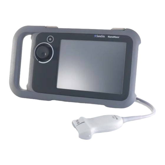
Chapter 1: Getting Started About the system The NanoMaxx™ ultrasound system is a portable, software‐controlled device that acquires and displays high‐resolution, real‐time ultrasound images. Features available on your system depend on the configuration, transducer, and exam type. You need a license key to activate the software. See “Software licensing” on page 33. Basic steps 1 Turn the system on. 2 Attach a transducer. 3 Tap Patient, and complete the patient information form. 4 Tap Mode and select an imaging mode. By default, the system is in 2D imaging. Figure 1 System front (top) and back (bottom) Handle Knob... -
Page 12: Preparing The System
Preparing the system Kickstand The kickstand lets you set the system upright on a flat surface. You can extend the kickstand as Compartments and connectors needed for your optimal viewing angle. The back of the system has a battery compartment, a transducer compartment, and a connector for the NanoMaxx™ dock. The side has two USB ports. (See Figure 1 on page 1.) Dock The dock has ports for the power supply, printer cable, and more. It attaches to the back of the system. (See Figure 1 on page 1.) Each port has a symbol that describes its use. Connectivity symbols on dock Figure 2 Back of system with kickstand extended Symbol Definition Installing or removing the battery... -
Page 13: Using Ac Power And Charging The Battery
Do not use the system if an error The battery charges when the system is message appears on the screen. connected to the AC power supply. A fully Note the error code and turn off the discharged battery recharges in less than five system. Call SonoSite or your local hours. representative. The system can run on AC power and charge the battery if AC power is connected to the system. To turn the system on or off The system can run on battery power for up to ... -
Page 14: Inserting And Removing Usb Storage Devices
You can also import and export user accounts and the Event log using a USB storage device. Note: SonoSite supports the USB storage device included optionally with the system. Other brands are untested and may not perform as expected. WARNING: To avoid damaging the USB storage device and losing patient data from it, observe the following: • Do not remove the USB storage device or turn off the ultrasound... -
Page 15: Screen Layout
To remove a USB storage device Patient header Removing the USB storage device while the Includes current patient name, patient ID number, institution, user, date, and time. system is exporting may cause the exported files to be corrupted or incomplete. Depth marker Marks in .5 cm, 1 cm, and 5 cm increments 1 Wait at least five seconds after the USB depending on depth. To specify style, see animation stops. -
Page 16: Knob
Entering text Caution: To avoid damage to the transducer, use only gels recommended by In forms and annotations, you can enter text in SonoSite. Using gels other than the text fields using the on‐screen keyboard. one recommended by SonoSite can To enter text using the on-screen keyboard damage the transducer and void the warranty. If you have questions 1 Tap a text field. -
Page 17: Intended Uses
24. transducer sheath and gel until you are ready to perform the Abdominal Imaging Applications You can assess procedure. the liver, kidneys, pancreas, spleen, gallbladder, bile ducts, transplanted organs, abdominal To apply a transducer sheath vessels, and surrounding anatomical structures for the presence or absence of pathology SonoSite recommends the use of market‐cleared, transabdominally. transducer sheaths for intracavitary or surgical applications. To lessen the risk of contamination, Cardiac Imaging Applications You can assess the install the sheath only when you are ready to heart, cardiac valves, great vessels, surrounding perform the procedure. anatomical structures, overall cardiac performance, and heart size for the presence or 1 Place gel inside the sheath. - Page 18 WARNING: To prevent injury or misdiagnosis, do not use this system for Percutaneous Umbilical Blood Sampling (PUBS) or in vitro Fertilization (IVF) The system has not been validated to be proven effective for these two uses. CPD or Color images can be used as an adjunctive method, not as a screening tool, for the following: •...
-
Page 19: Chapter 2: System Setup
Chapter 2: System Setup The setup pages let you customize the system Administration setup and set preferences. On the Administration setup page, you can configure the system to require users to log in Displaying the setup pages and enter passwords. Required login helps protect patient data. You can also add and delete To display a setup page users, change passwords, import and export user accounts, and display the Event log. 1 Tap Options and select Setup. 2 Do any of the following: Security settings • Select the setup page from the Page list. WARNING: Health care providers who maintain • Tap Previous or Next until the page or transmit health information are appears. -
Page 20: User Setup
2 Type the administrator password in the 3 Under User Information, fill in the Name, Password box. Password, and Confirm boxes. (See “Choosing a secure password” on page 11.) If you need the administrator password, contact SonoSite. (See “SonoSite Technical 4 (Optional) In the User box, type the user’s Support” on page vii.) initials to display them in the patient header and in the User box in the patient information 3 Tap Login. form. To log out as Administrator 5 (Optional) Select the Administration Access check box to allow access to all administration Turn off or restart the system. privileges. To require user login 6 Tap Save. You can set the system to display the User Login screen at startup. -
Page 21: Exporting And Clearing The Event Log
To export user accounts 3 Select the USB storage device, and tap Export. 1 Insert a USB storage device. The Event log is a text file that you can open in a text‐editing application (for example, Microsoft 2 Log in as Administrator. Word or Notepad). 3 Tap Export. A list of USB devices appears. To clear the Event log 4 Select the USB storage device, and tap Export. 1 Display the Event log. All user names and passwords are copied to 2 Tap Clear. the USB storage device. Passwords are encrypted. 3 Tap Yes. To import user accounts Logging in as user 1 Insert the USB storage device that contains the If user login is required, the User Login screen ... -
Page 22: Annotations Setup
Annotations setup To import predefined label groups 1 Insert the USB storage device that contains the On the Annotations setup page, you can label groups. customize predefined labels and set the 2 On the Annotations setup page, tap Import. preference for managing text when unfreezing images. 3 Select the USB storage device, and then tap Import. For instructions to annotate images, see “Annotating images” on page 19. 4 Tap OK in the dialog box that appears. To predefine a label group All predefined label groups for all exams are replaced with those from the USB storage You can specify which labels are available for an device. exam type when annotating an image. (See “To place text or a label” on page 19.) Audio, Battery setup 1 In the Exam list on the Annotations setup page, select the exam type whose labels you ... -
Page 23: Date And Time Setup
To receive storage alerts Presets setup On the Connectivity setup page, select The Presets setup page has settings for general Internal Storage Capacity Alert. preferences. You can select from the following The system displays a message if internal lists and can calibrate the touchscreen. storage is near capacity when you end an Depth Markers: Type 1 displays unnumbered exam. markers, with the maximum depth number in the lower right screen. Type 2 displays markers with Date and Time setup numbers. Thermal Index: You can select TIS, TIB, or TIC. The To set the date and time default setting is based on exam type: OB is TIB, On the Date and Time setup page, do the and all others are TIS. ... -
Page 24: Usb Devices Setup
To specify a file format for exported images To specify AE title 1 On the USB Devices setup page, tap Export. The AE title identifies your system with exported 2 Under USB Export, select an export type: images that you import to a PACS archiver. • SiteLink organizes files in a folder On the USB Devices setup page, type a unique structure similar to that from SiteLink™ name for your system in the AE Title text box. image manager. (Default is NanoMAXX.) • DICOM creates files readable by a DICOM To include private tags reader. If you use DICOM export type and a SonoSite 3 Select an image format for your export type. software product, include private tags on the For JPEG image format, also select a JPEG images. compression. On the USB Devices setup page, select Include A high compression has a smaller file size but ... - Page 25 software, you should transfer or export them using BMP format. SonoCalc ® IMT software uses a sophisticated algorithm to measure images, and lossy‐compression may cause errors. For more information on using lossy‐compressed images, consult the industry literature, including the following references: “Physics in Medicine and Biology, Quality Assessment of DSA, Ultrasound and CT Digital Images Compressed with the JPEG Protocol,” D Okkalides et al 1994 Phys Med Biol 39 1407‐1421 doi: 10.1088/0031‐9155/39/9/008 www.iop.org/EJ/abstract/0031‐9155/39/9/008 “Canadian Association of Radiologists, CAR Standards for Irreversible Compression in Digital Diagnostic Imaging within Radiology,” Approved: June 2008. www.car.ca/Files/%5CLossy_Compression. Chapter 2: System Setup...
- Page 26 USB Devices setup...
-
Page 27: Chapter 3: Imaging
Chapter 3: Imaging Imaging modes 2D controls The current optimization setting Imaging modes available depend on the appears below the icon: transducer and exam type. See “Imaging modes and exams available by transducer” on page 24. Res provides the best resolution. Gen provides a balance between 2D imaging resolution and penetration. Pen provides the best penetration. 2D is the systemʹs default imaging mode. The Some of the parameters optimized to system displays echoes in two dimensions by ... -
Page 28: Cpd And Color Doppler Imaging
3 Adjust controls as desired. 2 Drag the ROI box as needed. Many optimization and depth settings A green outline shows the change. available in 2D imaging are also available in M Mode imaging. See “2D controls” on Adjusting depth and gain page 17. To display the M Mode trace To adjust depth 1 Display the M‐line. You can adjust the depth in all imaging modes. The vertical depth scale is marked in 0.5 cm, 1 cm, Adjust the depth if necessary. (See “To adjust and 5 cm increments, depending on the depth. To depth” on page 18.) change the style of depth markers, see “Presets 3 Do either of the following: setup” on page 13. •... -
Page 29: Freezing, Viewing Frames, And Zooming
Freezing, viewing frames, and Guidelines are for needle guidance and are an optional feature.This feature depends on the zooming transducer and exam type. For more information, see SonoSite Bracket and Needle Guide User Guide. To freeze or unfreeze an image To turn guidelines on or off Tap Freeze or Unfreeze. On a 2D image, tap To move forward or backward in the cine buffer Annotating images 1 Freeze the image. -
Page 30: Adjusting Screen Brightness
To reset the home position To return to the previous screen, tap Back. The home position is where the cursor initially appears. Adjusting screen brightness 1 Tap Annotate, and select Text. A green cursor The screen brightness affects battery life. To appears. conserve battery life, adjust brightness to a lower 2 Drag the cursor where desired. setting. 3 Tap Home Set. To adjust the screen brightness To return to the previous screen, tap Back. In 2D imaging, tap and then turn the To place an arrow knob. You can add an arrow graphic to point out a specific part of the image. Patient information form 1 Tap Annotate, and select Arrow. -
Page 31: Patient Information Form Fields
• Accession Enter number, if applicable Caution: If the internal storage icon does not appear in the system status area, • Gender internal storage may be defective. • Date of birth Contact SonoSite Technical Support. (See “SonoSite Technical Exam Support” on page vii.) • Type Exam types available depend on ... - Page 32 To edit patient information from the patient list You can edit the patient name and ID from the patient list instead of from the patient information form if the exam is closed but has not been exported. 1 In the patient list, select the patient exam. 2 Tap Edit. 3 Fill in the form fields, and tap OK. To append images to a patient exam Although you cannot add images to a patient exam that is ended, exported, or archived, you can automatically start a new patient exam that Figure 1 Patient list has the same patient information. Depending on your archiver, the two exams appear as one study To display the patient list when exported. 1 In 2D, do one of the following: 1 Select the patient exam in the patient list.
-
Page 33: Printing And Deleting Images
To review images for the current patient • Print all images for multiple patient exams: Select one or more patient exams 1 Tap Options and select Review. in the patient list. Then tap Print. Two numbers (x/x) appear: the file displayed • Print all images for one patient exam: and the total files saved. Highlight the patient exam in the patient 2 Turn the knob or tap the arrows (< >) to cycle list, and tap Print. through images. Each image appears briefly on‐screen while printing. To display the patient list, tap List. To return to imaging, tap Done. To delete images 1 Select one or more patient exams in the patient Printing and deleting images list. WARNING: To avoid damaging the USB storage 2 Tap Delete to delete the selected exams. A ... -
Page 34: Imaging Modes And Exams Available By Transducer
Insert the USB storage device. (See “Inserting To change the exam type and removing USB storage devices” on Do one of the following: page 4.) • In 2D imaging, tap Exam, and select the 2 In the patient list, select the patient exams you exam type. want to export, and then tap Exp. USB. • On the patient information form, select the 3 If prompted, select the USB storage device. If exam type in the Type list under Exam. you want to hide patient information, deselect (See “Patient information form” on page 20.) Include patient information on images. Imaging modes and exams available Only available USB devices are selectable. Note: You can avoid prompts to select the USB Imaging mode storage device. See “To specify how patient exams ... -
Page 35: Chapter 4: Measurements And Calculations
Chapter 4: Measurements and Calculations With the NanoMaxx ultrasound system, you can If you prefer to select a measurement name take distance measurements on an image. In the before performing a measurement, start a IMT (also called Carotid IMT or CIMT) or OB calculation. See “Calculations” on page 27. exam, you can also take measurements for To save a measurement to a calculation and calculations, which save to a patient report. patient report Measurements are performed on frozen images. 1 With the measurement active (green), tap For references used, see Chapter 7, “References.” Calcs. Measurements 2 From the lefthand controls, select a measurement name. You can take measurements in any imaging mode Only measurement names available for the and can save the image with the measurements imaging mode and exam type are selectable. displayed. (OB) HC and AC use an ellipse for measuring ... -
Page 36: Measuring
With the measurement active, do any of the 1 On a frozen image, tap Calipers. following: A set of calipers appears, connected by a • Knob: dotted line and labelled A. Turn the knob. Tap Left/Right, Up/Down or Small/Large (if present) as necessary to 2 Position the first caliper where desired. (See set the behavior. “To position calipers” on page 25.) • Touchscreen: 3 Tap Select. Tap Touch screen. Using your finger, drag The second caliper becomes active. the active caliper. 4 Position the second caliper where desired. You can also use the knob as needed. 5 If you want an additional set of calipers, To return to the previously displayed controls, press the knob. Caliper. To switch the active calipers A set of calipers labelled B appears. Position Do one of the following: the calipers where desired. -
Page 37: Calculations
Calculations 2 Tap Measurements you take for calculations save to A vertical caliper appears. the patient report. You can display, redo, and 3 Position the vertical caliper at the peak of the delete saved measurements from a calculation. heartbeat, and then tap Select. (See “To For exam type availability, see “Imaging modes position calipers” on page 25.) and exams available by transducer” on page 24. A second vertical caliper appears. IMT calculations 4 Position the second vertical caliper at the peak of the next heartbeat. Tapping Select toggles between the calipers. WARNING: To ensure high quality images, all patient images must be obtained See also “To measure fetal heart rate (FHR)” on by qualified and trained individuals. page 31. - Page 38 To perform an IMT measurement IMT tool controls Repeat this procedure for each IMT measurement The IMT tool has the following controls. you want to take. Left/Right, Repositions the tool horizontally or 1 On a frozen 2D image, tap Calcs. Up/Down vertically. • With Left/Right, turn the knob 2 Tap Right or Left for the side measured. clockwise to move the tool right, The setting displayed is the side measured. or counter-clockwise to move the tool left.
-
Page 39: Ob Calculations
To measure plaque WARNING: To avoid incorrect OB calculations, verify with a local clock and 1 On a frozen 2D image, tap Calcs. calendar that the system’s date and 2 Tap Right or Left for the side measured. time settings are correct before each use of the system. The system 3 Tap Plaque, and select Plaq 1 or Plaq 2. does not automatically adjust for A set of calipers appears. - Page 40 Ratios HC/AC Campbell Gestational OB Calculation Table FL/AC Hadlock Measurements Result Authors FL/BPD Hohler Gestational Hansmann, FL/HC Hadlock Nyberg, Tokyo U. Amniotic Jeng Fluid Index Hadlock, Hansmann, a. The Gestational Age is automatically calculated and displayed Osaka, next to the OB measurement you selected. The average of the Tokyo U.
-
Page 41: Patient Report
b Position the calipers. (See “To position To delete a measurement result from the calipers” on page 25.) patient report 1 In the patient report, tap the measurement c Tap Save. result. To measure fetal heart rate (FHR) The measurement result is highlighted green. 1 On a frozen M Mode trace, tap Calcs. 2 Tap Delete. 2 Tap FHR. A vertical caliper appears. 3 Position the vertical caliper at the peak of the heartbeat, and then tap Select. (See “To position calipers” on page 25.) A second vertical caliper appears. - Page 42 Calculations...
-
Page 43: Chapter 5: Troubleshooting And Maintenance
Chapter 5: Troubleshooting and Maintenance This chapter contains information to help correct Verify that you are using a supported transducer. problems with system operation, to enter a A maintenance icon appears System software license, and to take proper care of the system, transducer, and accessories. maintenance may be required. Record the number in parentheses on the C: line and contact SonoSite or your SonoSite representative. Troubleshooting If you encounter difficulty with the system, use Software licensing the following list to help troubleshoot the problem. If the problem persists, contact SonoSite SonoSite software is controlled by a license key. Technical Support. (See “SonoSite Technical After you install new software, the system Support” on page vii.) prompts you for a license key. You must obtain one key for the system and one key for the System does not turn on Check all power transducer. connections. The software will operate for a short time (the ... -
Page 44: Maintenance
WARNING: The level of disinfection required for On occasion, a software upgrade may be a device is dictated by the type of required. SonoSite provides a USB device tissue it will contact during use. To containing the software. avoid infection, ensure that the disinfectant type is appropriate for To enter a license key the equipment. -
Page 45: Cleaning And Disinfecting Transducers
instructions for solution strengths and Caution: Do not spray cleaners or disinfectant contact duration. disinfectant directly on the system surfaces. Doing so may cause 5 Wipe surfaces with the disinfectant solution. solution to leak into the system, 6 Air dry or towel dry with a clean cloth. damaging the system and voiding the warranty. Cleaning and disinfecting transducers Do not use strong solvents such as To disinfect the transducer and its cable, use the ... - Page 46 (31‐46 cm) from the point where the cable Apply the solution to the cloth rather than the enters the connector. surface. Follow the instructions on the disinfectant 4 Rinse with water or wipe with label for the duration of the transducer water‐dampened cloth, and then wipe with a immersion. dry cloth. 7 Using the instructions on the disinfectant 5 Mix the disinfectant solution compatible with label, rinse to the point of the previous the transducer, following disinfectant label immersion, and then air dry or towel dry with instructions for solution strengths and a clean cloth. disinfectant contact duration. 8 Examine the transducer and cable for damage 6 Wipe surfaces with the disinfectant solution. such as cracks, splitting, or fluid leaks. 7 Air dry or towel dry with a clean cloth. If damage is evident, discontinue use of the 8 Examine the transducer and cable for damage transducer, and contact SonoSite or your local such as cracks, splitting, or fluid leaks. representative. If damage is evident, discontinue use of the transducer, and contact SonoSite or your local representative. Cleaning and disinfecting...
-
Page 47: Cleaning And Disinfecting The Battery Or Dock
Cleaning and disinfecting the battery or dock Caution: To avoid damaging the battery, do not allow cleaning solution or disinfectant to come in contact with the battery terminals. To clean and disinfect the battery or dock (wipe method) 1 Remove the battery or dock from the system. 2 Clean the surface using a soft cloth lightly ... - Page 48 Cleaning and disinfecting...
-
Page 49: Chapter 6: Safety
Chapter 6: Safety This chapter contains information required by regulatory agencies, including information about the ALARA (as low as reasonably achievable) principle, the output display standard, acoustic power and intensity tables, and other safety information. The information applies to the ultrasound system, transducer, accessories, and peripherals. Ergonomic safety These healthy scanning guidelines are intended to assist you in the comfort and effective use of your ultrasound system. WARNING: To prevent musculoskeletal disorders, follow the guidelines in this section. Use of an ultrasound system may be linked to musculoskeletal disorders a,b,c Use of an ultrasound system is defined as the physical interaction among the operator, the ultrasound system, and the transducer. -
Page 50: Position The System
Vanderpool, H.E., E.A. Friis, B.S. Smith, and K.L. Harms. “Prevalence of Carpal Tunnel Syndrome and Other Work-related Musculoskeletal Problems in Cardiac Sonographers. ” Journal of Medicine. 35:6 (1993), 605-610. Position the system Promote comfortable shoulder, arm, and hand postures Use a stand to support the weight of the ultrasound system. Minimize eye and neck strain •... -
Page 51: Take Breaks, Exercise, And Vary Activities
Take breaks, exercise, and vary activities • Minimizing scanning time and taking breaks can effectively allow your body to recover from physical activity and help you avoid MSDs. Some ultrasound tasks may require longer or more frequent breaks. However, simply changing tasks can help some muscle groups relax while others remain or become active. • Work efficiently by using the software and hardware features correctly. • Keep moving. Avoid sustaining the same posture by varying your head, neck, body, arm, and leg positions. • Targeted exercises can strengthen muscle groups, which may help you avoid MSDs. Contact a qualified health professional to determine stretches and exercises that are right for you. Electrical safety classification Class I equipment The ultrasound system is classified as Class I equipment when powered from the power supply or mounted on the stand because the external power supply is a Class I protectively earthed power supply. -
Page 52: Electrical Safety
• Do not touch any of the following: • The ungrounded signal input/output connectors on the NanoMaxx dock. • The system battery contacts (inside the battery compartment). • Do not connect the system’s power supply or the stand’s auxillary mains outlet receptables to an MPSO or extension cord. - Page 53 Do not use the system if an error message appears on the image display: note the error code; call SonoSite or your local representative; turn off the system by pressing and holding the power key until the system powers down.
-
Page 54: Equipment Safety
Equipment safety To protect your ultrasound system, transducer, and accessories, follow these precautions. Caution: Excessive bending or twisting of cables can cause a failure or intermittent operation. Improper cleaning or disinfecting of any part of the system can cause permanent damage. For cleaning and disinfecting instructions, see Chapter 5, “Troubleshooting and Maintenance. -
Page 55: Clinical Safety
If the battery emits an odor or heat, is deformed or discolored, or in any way appears abnormal during use, recharging or storage, immediately remove it and stop using it. If you have any questions about the battery, consult SonoSite or your local representative. -
Page 56: Hazardous Materials
Hazardous materials WARNING: The liquid crystal display (LCD) contains mercury. Dispose of the LCD properly in accordance with local regulations. Electromagnetic compatibility The ultrasound system has been tested and found to comply with the electromagnetic compatibility (EMC) limits for medical devices to IEC 60601‐1‐2:2007. These limits are designed to provide reasonable protection against harmful interference in a typical medical installation. Caution: Medical electrical equipment requires special precautions regarding EMC and must be installed and operated according to these instructions. It is possible that high levels of radiated or conducted radio-frequency electromagnetic interference (EMI) from portable and mobile RF communications equipment or other strong or nearby radio-frequency sources, could result in performance disruption of the ultrasound... -
Page 57: Manufacturer's Declaration
SonoSite could result in malfunctioning of your ultrasound system or other medical electrical devices in the area. Contact SonoSite or your local representative for a list of accessories and peripherals available from or recommended by SonoSite. See the SonoSite accessories user guide. - Page 58 0.5 cycle for 0.5 cycle and voltage environment. If the user of the 40% U 40% U variations on SonoSite ultrasound system power supply requires continued operation (60% dip in U ) for 5 (60% dip in U ) for...
- Page 59 Portable and mobile RF communications equipment IEC 61000-4-6 150 kHz to 80 MHz should be used no closer to any part of the SonoSite ultrasound system including cables, than the recommended separation distance calculated from the equation applicable to the frequency of the transmitter.
-
Page 60: Alara Principle
If the measured field strength in the location in which the SonoSite ultrasound system is used exceeds the applicable RF compliance level above, the SonoSite ultrasound system should be observed to verify normal operation. If abnormal performance is observed, additional measures may be necessary, such as re-orienting or relocating the SonoSite ultrasound system. -
Page 61: Applying Alara
penetration, resolution, and field of view. The default system presets are reset at the start of each new patient. It is the scanning technique of the qualified ultrasound user along with patient variability that determines the system settings throughout the exam. The variables which affect the way the qualified ultrasound user implements the ALARA principle include: patient body size, location of the bone relative to the focal point, attenuation in the body, and ultrasound exposure time. Exposure time is an especially useful variable, because the qualified ultrasound user can control it. The ability to limit the exposure over time supports the ALARA principle. Applying ALARA The system imaging mode selected by the qualified ultrasound user is determined by the diagnostic information required. 2D imaging provides anatomical information; CPD imaging provides information about the energy or amplitude strength of the Doppler signal over time at a given anatomical location and is used for detecting the presence of blood flow; Color imaging provides information about the energy or amplitude strength of the Doppler signal over time at a given anatomical location and is used for detecting the presence, velocity, and direction of blood flow; Tissue Harmonic Imaging uses higher received frequencies to reduce clutter, artifact, and improve resolution on the 2D image. Understanding the nature of the imaging mode used allows the qualified ultrasound user to apply the ALARA principle. Prudent use of ultrasound requires that patient exposure to ultrasound be limited to the lowest ultrasound output for the shortest time necessary to achieve acceptable diagnostic results. Decisions that support prudent use are based on the type of patient, exam type, patient history, ease or difficulty of obtaining diagnostically useful information, and potential localized heating of the patient due to transducer surface temperature. The system has been designed to ensure that temperature at the face of the transducer will not exceed the limits established in Section 42 of EN 60601‐2‐37: Particular requirement for the safety of ultrasound medical diagnostic and monitoring equipment. See “Transducer surface temperature rise” on page 56. In the event of a device malfunction, there are redundant controls that limit transducer power. This is accomplished by an electrical design that limits both power supply current and voltage to the transducer. The sonographer uses the system controls to adjust image quality and limit ultrasound output. The system controls are divided into three categories relative to output: controls that directly affect output, controls that indirectly affect output, and receiver controls. Direct controls The system does not exceed a spatial peak temporal average intensity (ISPTA) of 720 mW/cm for all imaging modes. The mechanical index (MI) and thermal index (TI) may exceed values greater than 1.0 on some transducers in some imaging modes. One may monitor the MI and TI ... -
Page 62: Indirect Controls
Indirect controls The controls that indirectly affect output are controls affecting imaging mode, freeze, and depth. The imaging mode determines the nature of the ultrasound beam. Tissue attenuation is directly related to transducer frequency. The higher the PRF (pulse repetition frequency), the more output pulses occur over a period of time. Receiver controls The receiver controls are the gain controls. Receiver controls do not affect output. They should be used, if possible, to improve image quality before using controls that directly or indirectly affect output. Acoustic artifacts An acoustic artifact is information, present or absent in an image, that does not properly indicate the structure or flow being imaged. There are helpful artifacts that aid in diagnosis and those that hinder proper interpretation. Examples of artifacts include: • Shadowing • Through transmission • Aliasing • Reverberations • Comet tails For more information on detecting and interpreting acoustic artifacts, see the following reference: Kremkau, Frederick W. Diagnostic Ultrasound: Principles and Instruments. 7th ed., W.B. Saunders Company, (Oct. 17, 2005). Guidelines for reducing MI and TI The following are general guidelines for reducing MI or TI. If multiple parameters are given, the best results may be achieved by minimizing these parameters simultaneously. In some modes, changing these parameters does not affect MI or TI. Changes to other parameters may also result in MI and TI reductions. Please note the MI and TI values on the right side of the screen. - Page 63 Table 3: MI Transducer Depth ↑ C11n ↑ C60n ↑ L25n ↑ L38n ↑ P21n ↓ Decrease or lower setting of parameter to reduce MI. ↑ Increase or raise setting of parameter to reduce MI. Table 4: TI (TIS, TIC, TIB) CPD Settings Transducer Depth...
-
Page 64: Output Display
TIC, TIB, or TIS L25n/13-6 TIC,TIB, or TIS L38n/10-5 TIC, TIB, or TIS P21n/5-1 TIC, TIB, or TIS Even when MI is less than 1.0, the system provides a continuous real‐time display of MI in all imaging modes, in increments of 0.1. The system meets the output display standard for TI and provides a continuous real‐time display of TI in all imaging modes, in increments of 0.1. The TI consists of three user‐selectable indices, and only one of these is displayed at any one time. In order to display TI properly and meet the ALARA principle, the user selects an appropriate TI based on the specific exam being performed. SonoSite provides a copy of AIUM Medical Ultrasound Safety, which contains guidance on determining which TI is appropriate (See “Related guidance documents” on page 55). MI and TI output display accuracy The accuracy result for the MI is stated statistically. With 95% confidence, 95% of the measured MI values will be within +18% to –25% of the displayed MI value, or +0.2 of the displayed value, whichever value is larger. The accuracy result for the TI is stated statistically. With 95% confidence, 95% of the measured TI values will be within +21% to –40% of the displayed TI value, or +0.2 of the displayed value, whichever value is larger. The values equate to +1dB to –3dB. -
Page 65: Factors That Contribute To Display Uncertainty
A displayed value of 0.0 for MI or TI means that the calculated estimate for the index is less than 0.05. Factors that contribute to display uncertainty The net uncertainty of the displayed indices is derived by combining the quantified uncertainty from three sources: measurement uncertainty, system and transducer variability, and engineering assumptions and approximations made when calculating the display values. Measurement errors of the acoustic parameters when taking the reference data are the major source of error that contributes to the display uncertainty. The measurement error is described in “Acoustic measurement precision and uncertainty” on page 70. The displayed MI and TI values are based on calculations that use a set of acoustic output measurements that were made using a single reference ultrasound system with a single reference transducer that is representative of the population of transducers of that type. The reference system and transducer are chosen from a sample population of systems and transducers taken from early production units, and they are selected based on having an acoustic output that is representative of the nominal expected acoustic output for all transducer/system combinations that might occur. Of course every transducer/system combination has its own unique characteristic acoustic output, and will not match the nominal output on which the display estimates are based. This variability between systems and transducers introduces an error into displayed value. By doing acoustic output sampling testing during production, the amount of error introduced by the variability is bounded. The sampling testing ensures that the acoustic output of transducers and systems being manufactured stays within a specified range of the nominal acoustic output. Another source of error arises from the assumptions and approximations that are made when deriving the estimates for the display indices. Chief among these assumptions is that the acoustic output, and thus the derived display indices, are linearly related with the transmit drive voltage of the transducer. Generally, this assumption is very good, but it is not exact, and thus some error in the display can be attributed to the assumption of voltage linearity. Related guidance documents • Information for Manufacturers Seeking Marketing Clearance of Diagnostic Ultrasound Systems and Transducers, FDA, 2008. • Medical Ultrasound Safety, American Institute of Ultrasound in Medicine (AIUM), 2008. (A copy is included with each system.) •... -
Page 66: Transducer Surface Temperature Rise
Transducer surface temperature rise Table 6 lists the measured surface temperature rise from ambient (23°C ± 3°C) of transducers used on the ultrasound system. The temperatures were measured in accordance with EN 60601‐2‐37 section 42 with controls and settings positioned to give maximum temperatures. Table 6: Transducer Surface Temperature Rise External Use (°C) Test C11n C60n L25n L38n P21n Still air 15.3 15.9 15.8 14.8 16.6 Simulated use Acoustic output measurement Since the initial use of diagnostic ultrasound, the possible human biological effects (bioeffects) from ultrasound exposure have been studied by various scientific and medical institutions. In October 1987, the American Institute of Ultrasound in Medicine (AIUM) ratified a report from its Bioeffects Committee (Bioeffects Considerations for the Safety of Diagnostic Ultrasound, J Ultrasound Med., Sept. 1988: Vol. 7, No. 9 Supplement). The report, sometimes referred to as the Stowe Report, reviewed available data on possible effects of ultrasound exposure. Another ... -
Page 67: Tissue Models And Equipment Survey
where: In Situ = In Situ intensity value Water = Water intensity value e = 2.7183 a = attenuation factor (dB/cm MHz) Attenuation factor (a) for various tissue types: brain = 0.53 heart = 0.66 kidney = 0.79 liver = 0.43 muscle = 0.55 l = skinline to measurement depth in cm f = center frequency of the transducer/system/mode combination in MHz Since the ultrasonic path during the exam is likely to pass through varying lengths and types of tissue, it is difficult to estimate the true In Situ intensity. An attenuation factor of 0.3 is used for general reporting purposes; therefore, the In Situ value commonly reported uses the formula: In Situ (derated) = Water [e ‐(0.069lf) Since this value is not the true In Situ intensity, the term “derated” is used to qualify it. The maximum derated and the maximum water values do not always occur at the same operating conditions; therefore, the reported maximum water and derated values may not be related by the In Situ (derated) formula. For example: a multi‐zone array transducer that has maximum water value intensities in its deepest zone, but also has the smallest derating factor in that zone. The same transducer may have its largest derated intensity in one of its shallowest focal zones. Tissue models and equipment survey Tissue models are necessary to estimate attenuation and acoustic exposure levels In Situ from ... -
Page 68: Acoustic Output Tables
of fluid, as in many first and second‐trimester pregnancies scanned transabdominally, this model may underestimate the In Situ acoustic exposure. The amount of underestimation depends upon each specific situation. Fixed‐path tissue models, in which soft tissue thickness is held constant, sometimes are used to estimate In Situ acoustic exposures when the beam path is longer than 3 cm and consists largely of fluid. When this model is used to estimate maximum exposure to the fetus during transabdominal scans, a value of 1 dB/cm MHz may be used during all trimesters. Existing tissue models that are based on linear propagation may underestimate acoustic exposures when significant saturation due to non‐linear distortion of beams in water is present during the output measurement. The maximum acoustic output levels of diagnostic ultrasound devices extend over a broad range of values: • A survey of 1990‐equipment models yielded MI values between 0.1 and 1.0 at their highest output settings. Maximum MI values of approximately 2.0 are known to occur for currently available equipment. Maximum MI values are similar for real‐time 2D and M Mode imaging. • Computed estimates of upper limits to temperature elevations during transabdominal scans were obtained in a survey of 1988 and 1990 pulsed Doppler equipment. The vast majority of models yielded upper limits less than 1° and 4°C (1.8° and 7.2°F) for exposures of first‐trimester fetal tissue and second‐trimester fetal bone, respectively. The largest values obtained were approximately 1.5°C (2.7°F) for first‐trimester fetal tissue and 7°C (12.6°F) for second‐trimester fetal bone. Estimated maximum temperature elevations given here are for a “fixed path” tissue model and are for devices having I values greater than 500 mW/ SPTA . The temperature elevations for fetal bone and tissue were computed based on calculation procedures given in Sections 4.3.2.1‐4.3.2.6 in “Bioeffects and Safety of Diagnostic Ultrasound” (AIUM, 1993). Acoustic output tables The following tables indicate the acoustic output for the system and transducer combinations ... - Page 69 Table 7: Transducer Model: C60n/5-2 Operating Mode: 2D Non-scan Index Label Scan Non-scan ≤1 >1 aprt aprt Global Maximum Index Value — — — (MPa) 1.95 (mW) — — min of [W (mW) — TA.3 (cm) — (cm) — (cm) —...
- Page 70 Table 8: Transducer Model: C60n/5-2 Operating Mode: M Mode Non-scan Index Label Scan Non-scan ≤1 >1 aprt aprt Global Maximum Index Value — — (a&b) (MPa) 1.81 (mW) — min of [W (mW) — TA.3 (cm) — (cm) — (cm) z@PII .3max (cm)
- Page 71 Table 9: Transducer Model: C60n/5-2 Operating Mode: CPD/Color Non-scan Index Label Scan Non-scan ≤1 >1 aprt aprt Global Maximum Index Value — — — (MPa) 1.95 (mW) — — min of [W (mW) — TA.3 (cm) — (cm) — (cm) —...
- Page 72 Table 10: Transducer Model: L38n/10-5 Operating Mode: 2D Non-scan Index Label Scan Non-scan ≤1 >1 aprt aprt Global Maximum Index Value — — — (MPa) 3.23 (mW) — — min of [W (mW) — TA.3 (cm) — (cm) — (cm) —...
- Page 73 Table 11: Transducer Model: L38n/10-5 Operating Mode: M Mode Non-scan Index Label Scan Non-scan ≤1 >1 aprt aprt Global Maximum Index Value — — (MPa) 3.23 (mW) — 53.68 35.86 min of [W (mW) — TA.3 (cm) — (cm) — (cm) z@PII .3max...
- Page 74 Table 12: Transducer Model: L38n/10-5 Operating Mode: CPD/Color Non-scan Index Label Scan Non-scan ≤1 >1 aprt aprt Global Maximum Index Value — — — (MPa) 3.21 (mW) 47.37 — — min of [W (mW) — TA.3 (cm) — (cm) — (cm) —...
- Page 75 Table 13: Transducer Model: P21n/5-1 Operating Mode: 2D Non-scan Index Label Scan Non-scan ≤1 A >1 aprt aprt Global Maximum Index Value — — — (MPa) 1.974 (mW) — — 158.3 min of [W (mW) — TA.3 (cm) — (cm) —...
- Page 76 Table 14: Transducer Model: P21n/5-1 Operating Mode: M Mode Non-scan Index Label Scan Non-scan ≤1 A >1 aprt aprt Global Maximum Index Value — — (MPa) 1.841 (mW) — 80.66 80.66 min of [W (mW) — TA.3 (cm) — (cm) —...
- Page 77 Table 15: Transducer Model: P21n/5-1 Operating Mode: CPD/Color Non-scan Index Label Scan Non-scan ≤1 >1 aprt aprt Global Maximum Index Value — — — (MPa) 2.15 (mW) 119.7 — — 177.8 min of [W (mW) — TA.3 (cm) — (cm) —...
-
Page 78: Terms Used In The Acoustic Output Tables
Terms used in the acoustic output tables Table 16: Acoustic Output Terms and Definitions Term Definition Derated spatial peak, temporal average intensity in units of milliwatts/cm SPTA TI type Applicable thermal index for the transducer, imaging mode, and exam type. TI value Thermal index value for the transducer, imaging mode, and exam type. - Page 79 Table 16: Acoustic Output Terms and Definitions (Continued) Term Definition Equivalent beam diameter as a function of axial distance z, and is equal to ⁄ π ( ) ) Wo ⁄ z ( ) , where I (z) is the temporal-average intensity as a function of z in centimeters.
-
Page 80: Acoustic Measurement Precision And Uncertainty
Acoustic measurement precision and uncertainty All table entries have been obtained at the same operating conditions that give rise to the maximum index value in the first column of the table. Measurement precision and uncertainty for power, pressure, intensity, and other quantities that are used to derive the values in the acoustic output table are shown in the table below. In accordance with Section 6.4 of the Output Display Standard, the following measurement precision and uncertainty values are determined by making repeat measurements and stating the standard deviation as a percentage. Table 17: Acoustic Measurement Precision and Uncertainty Quantity Precision (% of standard deviation) Uncertainty (95% confidence) 1.9% +11.2% 1.9% +12.2% 3.4% +10% 0.1% +4.7% 3.2% +12.5 to -16.8% 3.2% +13.47 to -17.5%... -
Page 81: Labeling Symbols
Labeling symbols The following symbols are used on the products, packaging, and containers. Table 18: Labeling Symbols Symbol Definition Alternating Current (AC) Class 1 device indicating manufacturer’s declaration of conformance with Annex VII of 93/42/EEC Class 1 device requiring verification by the Notified Body of sterilization or measurement features, or to a Class IIa, IIb, or III device requiring verification or auditing by the Notified Body to applicable Annex(es) of 93/42/EEC 0086 Attention, see the user guide... - Page 82 Table 18: Labeling Symbols (Continued) Symbol Definition Corrugated recycle Dangerous voltage Date of manufacture Direct Current (DC) Do not get wet. Do not stack over 2 high. Do not stack over 5 high. Do not stack over 10 high. Electrostatic sensitive devices Device complies with relevant FCC regulations for electronic devices.
- Page 83 Table 18: Labeling Symbols (Continued) Symbol Definition Device emits a static (DC) magnetic field. Non-ionizing radiation Paper recycle Serial number type of control number Temperature limitation Atmospheric pressure limitation Humidity limitations Submersible. Protected against the effects of temporary immersion. Handle transducer with care. Type BF patient applied part (B = body, F = floating applied part) Underwriter’s Laboratories labeling...
- Page 84 Chinese national standards for many products sold in the People’s Republic of China. Contains mercury. (Applies to the LCD and may apply to other components in the ultrasound system.) WARNING: WARNING: Connect Only Connect Only Accessories and Peripherals Accessories and Peripherals Recommended by SonoSite Recommended by SonoSite...
-
Page 85: Chapter 7: References
Chapter 7: References Measurement accuracy Sources of measurement errors The measurements provided by the system do not define a specific physiological or anatomical In general, two types of errors can be introduced parameter. Rather, the measurements are of a into the measurement: physical property such as distance for evaluation by the clinician. The accuracy values require that Acquisition Error Includes errors introduced by you can place the calipers over one pixel. The the ultrasound system electronics relating to values do not include acoustic anomalies of the signal acquisition, signal conversion, and signal body. processing for display. Additionally, computational and display errors are introduced The 2D linear distance measurement results are by the generation of the pixel scale factor, displayed in centimeters with one place past the application of that factor to the caliper positions decimal point, if the measurement is ten or on the screen, and the measurement display. greater; two places past the decimal point, if the measurement is less than ten. Algorithmic Error The error introduced by measurements, which are input to higher order The linear distance measurement components calculations. This error is associated with have the accuracy and range shown in the ... -
Page 86: Ob References
Cardiovascular Health Study.” Stroke. Shepard M.J., V. A. Richards, R. L. Berkowitz, et (September 1991), 22,1155‐1163. al. “An Evaluation of Two Equations for Predicting Fetal Weight by Ultrasound.” Redberg, Rita F., MD and Vogel, Robert A., American Journal of Obstetrics and Gynecology, 142:1 MD, et al. “Task force #3—What is the (January 1, 1982), 47‐54. Spectrum of Current and Emerging Techniques for the Noninvasive Measurement Gestational Age (GA) by Last Menstrual of Atherosclerosis?” Journal of the American Period (LMP) College of Cardiology. (June 4, 2003), 41:11, The gestational age derived from the LMP date 1886‐1898. entered on the patient information form. OB references Results are displayed in weeks and days, and are calculated as follows: Amniotic Fluid Index (AFI) GA(LMP) = System date – LMP date Jeng, C. J., et al. “Amniotic Fluid Index Measurement with the Four Quadrant Technique Gestational Age (GA) by Last Menstrual During Pregnancy.” The Journal of Reproductive ... - Page 87 Biometry.” Japanese Journal of Medical Ultrasonics, Re‐evaluation of Relation to Menstrual Age (5‐18 23:12 (1996), 885. weeks) with High‐Resolution, Real‐Time Ultrasound.” Radiology, 182: (February 1992), 501‐505. WARNING: The gestational age calculated by Hansmann, M., et al. Ultrasound Diagnosis in your SonoSite system does not Obstetrics and Gynecology. New York: match the age in the Springer‐Verlag, (1985), 439. aforementioned reference at the 20.0 cm and 30.0 cm abdominal Osaka University. Ultrasound in Obstetrics and circumference (AC) measurements. Gynecology. (July 20, 1990), 20 and 96.
- Page 88 Nyberg, D.A., et al. “Transvaginal Ultrasound.” Mosby Yearbook, (1992), 76. Gestational sac measurements provide a fetal age based on the mean of one, two, or three distance measurements; however, Nyberg’s gestational age equation requires all three distance measurements for an accurate estimate. Tokyo University. “Gestational Weeks and Computation Methods.” Ultrasound Imaging Diagnostics, 12:1 (1982‐1). Head Circumference (HC) Chitty, L. S. and D.G. Altman. “New charts for ultrasound dating of pregnancy.” Ultrasound in Obstetrics and Gynecology 10: (1997), 174‐191, Table 5, 182. Hadlock, F., et al. “Estimating Fetal Age: Computer‐Assisted Analysis of Multiple Fetal Growth Parameters.” Radiology, 152: (1984), 497‐501. Hansmann, M., et al. Ultrasound Diagnosis in Obstetrics and Gynecology. New York: Springer‐Verlag, (1985), 431. Humerus Length (HL) Jeanty, P.; F. Rodesch; D. Delbeke; J. E. Dumont. “Estimate of Gestational Age from Measurements of Fetal Long Bones.” Journal of Ultrasound in Medicine. 3: (February 1984), 75‐79 Measurement publications...
-
Page 89: Chapter 8: Specifications
Chapter 8: Specifications This chapter contains system and accessory • V‐Universal Stand specifications and standards. The specifications for recommended peripherals are in the Peripheral manufacturers’ instructions. The following medical grade (conforming to EN 60601‐1 requirements) product is available for Supported transducers use with the ultrasound system. • C11n/8‐5 MHz (6 ft/1.8 m) Black‐and‐white printer • C60n/5‐2 MHz (5.5 ft/1.7 m) To order printer paper and other supplies or to • L25n/13‐6 MHz (7.5 ft/2.3 m) find the local distributor, contact Sony at www.sony.com/digitalphotofinishing. • L38n/10‐5 MHz (5.5 ft/1.7 m) Manufacturer’s instructions accompany each • P21n/5‐1 MHz (6 ft/1.8 m) peripheral. Imaging modes Environmental limits • 2D (256 gray shades) Operating • M Mode System, battery, and transducer •... -
Page 90: Electrical
Electrical UL 60601‐1 (1st Edition), Underwriters Laboratories, Medical Electrical Power Supply Input 100‐240 VAC, 50/60 Hz, 2.0 – Equipment‐Part 1: General Requirements for 1.0 A Safety. Power Supply Output #1 15 VDC, 5.0 A EMC standards classification Power Supply Output #2 12 VDC, 2.3 A Combined output not exceeding 75W EN 60601‐1‐2:2007, European Norm, Medical Electrical Equipment. General Requirements for Safety‐Collateral Standard. Electromagnetic Battery Compatibility. Requirements and Tests. The battery comprises six lithium‐ion cells plus CISPR11:2004, International Electrotechnical electronics, a temperature sensor, and battery Commission, International Special Committee on contacts. Radio Interference. Industrial, Scientific, and Medical (ISM) Radio‐Frequency Equipment Run time is at least 45 minutes, depending on Electromagnetic Disturbance imaging mode and display brightness. Characteristics‐Limits and Methods of ... -
Page 91: Terms
Glossary Terms For ultrasound terms not included in this glossary, refer to Recommended Ultrasound Terminology, Third Edition, published by the American Institute of Ultrasound in Medicine (AIUM). as low as reasonably The guiding principle of ultrasound use, which states that you should achievable (ALARA) keep patient exposure to ultrasound energy as low as reasonably achievable for diagnostic results. curved array Identified by the letter C (curved or curvilinear) and a number (for transducer example, 60). - Page 92 skinline A depth on the display that corresponds to the skin/transducer interface. SonoHD™ Imaging A subset of the 2D imaging mode in which the 2D image is enhanced Technology by reducing speckle noise artifact at tissue margins and improving contrast resolution by reducing artifacts and improving visualization of texture patterns within the image.
-
Page 93: Abbreviations
Abbreviations Abbreviations in User Interface Abbreviation Definition Abdomen Abdominal Circumference Amniotic Fluid Index Biparietal Diameter Cardiac Crown Rump Length Fetal Heart Rate Femur Length General, an optimization setting Gestational Sac Head Circumference Humerus Length Intima Media Thickness SonoMB Mechanical Index Musculoskeletal Nerve Obstetrical... - Page 94 Abbreviations in User Interface (Continued) Abbreviation Definition Tissue Harmonic Imaging Thermal Index Trimester Vascular Venous Last Menstrual Period Estab.DD Established Due Date...
-
Page 95: Index
Index Numerics OB 29 calipers 25, 27 2D imaging 17 cardiac, intended uses 7 Carotid IMT 25 cautions, definition vii CIMT 25 abbreviations 83 cine buffer 19 abdominal, intended uses 7 clean accessories list 79 battery 37 acoustic measurement precision 70 system 34 acoustic output touchscreen 35... - Page 96 error message 43 imaging modes errors list of 79 acquisition 75 transducer 24 algorithmic 75 import measurement 75 predefined label groups 12 estimated date of delivery (EDD) 76 user accounts 10 estimated fetal weight (EFW) 76 IMT calculations 27 Event log 11 in situ, definition 81 exam include private tags 14...
- Page 97 images 21 measurements 25 scanhead. See transducer calculations 29 screen brightness 20 intended uses 7 screen layout 5 references 76 security 9 optimize 17 setup pages 9 orientation marker 5 shipping specifications 79 output display 54 SiteLink 14 skin line, definition 82 sleep delay 12 software license 33 PAL, definition 81...
- Page 98 imaging modes 24 invasive or surgical use 7 linear array 81 preparation 6 problems 33 sheath 7 troubleshoot 33 ultrasound terminology 81 export 14, 23 insert or remove device 4 user accounts 10 user guide, conventions used vii user setup 10 uses, intended 7 vascular, intended uses 8 warnings, definition vii...
- Page 100 P12529-03 *P12529-03*...
Need help?
Do you have a question about the NanoMaxx and is the answer not in the manual?
Questions and answers