Table of Contents
Advertisement
Quick Links
Advertisement
Table of Contents

Related Manuals for SonoSite titan


Summary of Contents for SonoSite titan
- Page 1 Ultrasound System User Guide...
- Page 2 Non-SonoSite product names may be trademarks or registered trademarks of their respective owners. SonoSite products may be covered by one or more of the following U.S. patents: 4454884, 4462408, 4469106, 4474184, 4475376, 4515017, 4534357, 4542653, 4543960, 4552607, 4561807, 4566035, 4567895, 4581636, 4591355, 4603702, (4607642), 4644795, 4670339,...
-
Page 3: Table Of Contents
Contents Chapter 1: Introduction About the User Guide ................1 Conventions Used in This User Guide ..........2 Symbols and Terms Used in This User Guide ........2 Upgrades and User Guide Updates ............2 Customer Comments ................2 About the System ..................3 About the System Software ..............5 Chapter 2: Getting Started Healthy Scanning Guidelines ..............7 System Preparation .................10... - Page 4 Vascular Calculations ..............89 Cardiac Calculations ............... 92 Patient Report ..................101 Chapter 5: DICOM Connectivity TITAN System Setup for DICOM ............105 Ethernet Connection ................105 DICOM Setting Backup ............... 105 DICOM Configuration ................. 106 Configuring Locations ..............106 Configuring Archivers ..............
- Page 5 The ALARA Principle ................137 Applying ALARA ................137 Direct Controls ................138 Indirect Controls ................138 Receiver Controls ................138 Output Display ..................139 Related Guidance Documents .............140 Acoustic Output Measurement ............140 In Situ, Derated, and Water Value Intensities ......141 Tissue Models and Equipment Survey ........141 Intended Uses ..................142 About the Acoustic Output Table ............144 Acoustic Output Tables ..............146...
- Page 6 Chapter 9: Specifications System Dimensions ................203 Display Dimensions ................203 Transducers ................... 203 Imaging Modes ..................203 Applications ..................204 Image Storage ..................204 Accessories .................... 204 Hardware, Software, and Documentation ........ 204 Cables ....................205 Peripherals ..................... 205 Medical Grade ................
-
Page 7: Chapter 1: Introduction
Chapter 1: Introduction Please read the information in this user guide before using the TITAN high-resolution ultrasound system. It applies to the ultrasound system, and transducers. About the User Guide This user guide is a reference for using the ultrasound system. It is designed for a reader familiar with ultrasound techniques;... -
Page 8: Conventions Used In This User Guide
Questions and comments are encouraged. SonoSite is interested in your feedback regarding the system and the user guide. Please call SonoSite at 1-888-482-9449. If you are outside the USA, call the nearest SonoSite representative. You can also send electronic mail (e-mail) to SonoSite at the following address: comments@sonosite.com. -
Page 9: About The System
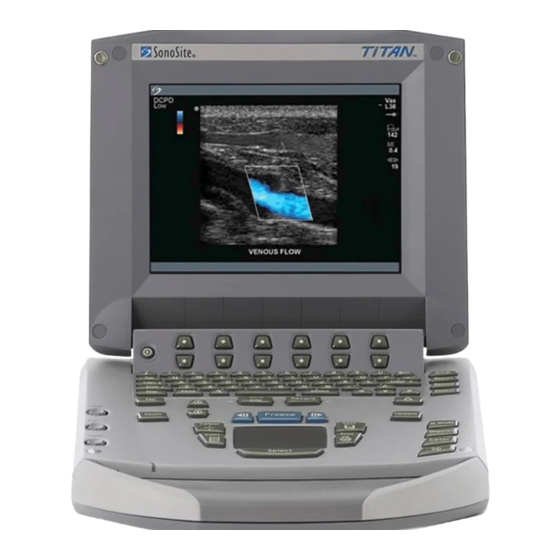
The ultrasound system has multiple configurations and feature sets. All are described in this user guide but not every option may apply to your system. System features are dependent on your system configuration, transducer, and exam type. Figure 1 TITAN System Front View Table 1: System Front Features Number... - Page 10 • L38/10-5 MHz 38 mm linear array System accessories include the following: TITAN mobile docking system, TITAN MDS Lite, TITAN mini-dock, Triple Transducer Connect, a power supply, a battery, ECG cable, video and printer cables, SiteLink Image Manager 2.2 software, and DICOM connectivity. See the TITAN Accessory User Guide for information on the accessories.
-
Page 11: About The System Software
The ultrasound system contains software that controls its operation. A software upgrade may be required. SonoSite will provide you with a CompactFlash card containing the software. Typically new software provides new capabilities. A single CompactFlash card can be used to update one or more systems. - Page 12 Chapter 1: Introduction...
-
Page 13: Chapter 2: Getting Started
Chapter 2: Getting Started This chapter contains information on healthy scanning practices, basic operation, and changing system settings. Healthy Scanning Guidelines These guidelines are intended to assist you in the comfort and effective use of your ultrasound system. Use of an ultrasound system may be linked to musculoskeletal disorders a,b,c Warning: Use of an ultrasound system is defined as the physical interaction between the... - Page 14 Position the System To promote comfortable shoulder, arm and hand postures, consider the following: • Use the TITAN mobile docking system to support the weight of the ultrasound system. To minimize eye strain, consider the following: • When the exam/procedure allows, position the system within reach.
- Page 15 Go Lightly To promote comfortable hand, wrist, and finger postures for your scanning arm, consider the following: • Hold the transducer lightly in your fingers. • Minimize the pressure applied on the patient. • Keep your wrist in a straight position. Take Breaks Minimizing scanning time and taking breaks can be very effective in allowing your body to recover from physical activity, which can help you avoid any MSDs.
-
Page 16: System Preparation
System Preparation Installing or Removing Battery The battery comprises six lithium-ion cells plus electronics, a temperature sensor, and battery contacts. If the battery is being installed for the first time, it will need to be charged. To avoid injury to the operator and to prevent damage to the ultrasound system, Warning: inspect the battery for leaks prior to installing. -
Page 17: Installing And Removing The Compactflash Card
Installing and Removing the CompactFlash Card Images are saved to a CompactFlash card and are organized in a patient list. The images in the patient list are organized alphabetically by the patient name and ID. Images are archived from the system to a PC using a USB or Ethernet connection. -
Page 18: Using Ac Power/Charging Battery
Connected to the mini-dock (See the TITAN Accessory User Guide.) • Connected to the docking system (See the TITAN Accessory User Guide.) To operate the system using AC power (directly to system): The equipment shall be connected to a center-tapped single phase supply circuit Warning: when users in the United States connect the equipment to a 240V supply system. -
Page 19: Connecting And Removing The Transducer
Connecting and Removing the Transducer The transducer connector can become hot during operation. This is normal. Warning: Operate the system in the docking system or on a flat, hard surface to allow air flow past the connector. The electrical contacts inside the system transducer connector may be damaged by Caution: foreign material. -
Page 20: System Controls
System Controls Caps Enter Shift Text Picto Delete Record Depth Zoom Update Freeze M Mode Caliper Save Doppler Calcs Print Color 12 13 Figure 3 System Controls Table 1: System Controls Number System Control Description Power Turns system on and off. Alphanumeric Use to enter text and numbers. - Page 21 Table 1: System Controls (Continued) Number System Control Description Zoom Magnifies image 2x. Gain Near Adjusts the gain applied to the near field of the image. Adjusts the gain applied to the far field of the image. Gain Adjusts the overall gain applied to the entire image.
-
Page 22: Screen Layout
Table 1: System Controls (Continued) Number System Control Description Freeze Freeze Stops the live imaging and displays a frozen image. Cine Review images stored in the cine buffer; (back/forward) back/forward through last-in, first-out sequence. All mode images can be stored and reviewed in the cine buffer. - Page 23 Table 2: Screen Layout Number Description Mode Data Displays current imaging mode information, e.g., Gen, Res, THI, and PW. Orientation Provides indication for image orientation. In dual and duplex Marker images, the orientation marker is green on the active screen. Text Displays text entered using keyboard.
-
Page 24: General Interaction
General Interaction Touchpad The touchpad is used to select, adjust, and move objects on the screen. For example, it controls the caliper position, CPD/DCPD/Color box position and size, floating cursor, and more. Note: The arrow keys control much of the same functionality as the touchpad. Context Menus The context menu, located at the bottom of the screen, provides controls that can be adjusted based on the system state. -
Page 25: Remappable Controls
Remappable Controls The remappable controls consists of six sets of 2-button groups at the top of the control panel. They adjust the values of each control displayed in the context menu. The buttons function in one of four ways, depending on context. Table 4: Remappable Control Options Control Description... - Page 26 Table 5: Keyboard Controls (Continued) Number Description Picto Turns pictographs on and off. Arrow Displays an arrow that can be moved and rotated within the image area. Spacebar Turns the keyboard on for text entry or adds a space. Delete Removes one character to the right of the cursor during text entry.
-
Page 27: Forms
Forms A floating cursor is available in the setup, patient, and report forms. The floating cursor allows interaction to occur using the touchpad and the Select key. For example, in the patient form, placing the floating cursor over the last name field and pressing the Select key will activate that field. Additionally, the floating cursor can be used to interact with the list and check boxes. - Page 28 SonoSite provides a comprehensive set of tools on the TITAN system that allows its customers to meet the applicable security requirements listed in the HIPAA standard. SonoSite's customers are ultimately responsible for ensuring the security and protection of all electronic protected health information collected, stored, reviewed and transmitted on the TITAN system.
- Page 29 • Selecting Off allows access to the TITAN system and does not require the user to enter a user name and password. After making changes in the Administration setup, reboot the system to log off as administrator.
- Page 30 To add new users: Figure 8 Setup Screen: User List Information Select New. Add New User In User Information, enter information in Name, Password, and Confirm fields. To ensure passwords are secure, it is recommended that passwords contain characters from the following categories: •...
- Page 31 Done To export or import user accounts: Note: Export and import are used to configure multiple systems and to back up user account information. Insert the CompactFlash card in the back slot of the TITAN Export User Account system. See “Installing and Removing the CompactFlash Card”...
- Page 32 Export Event Log (log.txt). When you export either one to the same CF card, it will overwrite the existing log.txt file. Insert the CompactFlash card in the back slot of the TITAN system. Select Log and then Export from the on-screen menu.
- Page 33 To login to system as user: Figure 10 User Login and Change Password Note: User Login is displayed when system access is turned on. In User Login, enter Name and Password and click OK. User Login In User Login, select Guest. Guest Login In Guest mode the user is able to scan but is restricted from accessing system setup and patient information.
- Page 34 To set up Audio and Battery: Figure 11 Setup Screen: Audio, Battery Press the Setup key. Key click Select Audio, Battery. In the Key click list, select On or Off. Press the Setup key. Beep alert Select Audio, Battery. In the Beep alert list, select On or Off. Press the Setup key.
- Page 35 Note: If PC is selected, the system allows report data to be sent as ASCII text from the TITAN system to a PC. Special third party software must be on the PC to acquire, view, or format the data into a report. Check the compatibility of your software with SonoSite technical support.
- Page 36 Press the Setup key. Ethernet Connectivity Select Connectivity. In the Transfer Mode list, select SiteLink. After changing connectivity, a dialog box is displayed to restart the system. Press the Setup key. Ethernet Setup Select Connectivity. Select Ethernet Setup. Enter information in the following fields: (see DICOM chapter for definition of terms) •...
- Page 37 To set Date and Time: Figure 13 Setup Screen: Date and Time An accurate date and time are critical for accurate obstetrics calculations. Verify Warning: that the date and time are accurate before each use of the system. The system does not automatically adjust for daylight savings time changes.
- Page 38 To set up Delta Key and F Keys: Figure 14 Setup Screen: Delta Key, F Keys Press the Setup key. Delta Key Select Delta Key, F Keys. Select desired functionality for the Delta key. The Delta key will now control this function. Press the Setup key.
- Page 39 To set up Display Information: Figure 15 Setup Screen: Display Information Press the Setup key. Patient Header Select Display Information. Select the desired check boxes to display desired information in the patient header. Press the Setup key. Mode Data Select Display Information. Select the desired check boxes to display imaging information on the screen.
- Page 40 This is only available when a user defined custom table has been created for the custom measurement. Insert a blank CompactFlash card in the back slot of the TITAN Export system.
- Page 41 Insert the CompactFlash card in the back slot of the TITAN Import system. Press the Setup key. Select OB Calculations. Select Import from the on-screen menu. After all user defined tables and measurements are imported, the system restarts. Note: All user defined tables and measurements currently on the system are replaced with imported data.
- Page 42 To set up OB custom measurements: Figure 17 Setup Screen: OB Custom Measurements Press the Setup key. OB Custom Select OB Custom Meas. Measurements Select New. In the Name field, enter a unique name. In the Type list, select the desired measurement type. Select Save.
- Page 43 To view and set up OB custom tables: Figure 18 Setup Screen: OB Custom Table Age Table Measurements: The system provides gestational age measurements by selected authors for the age table measurements listed in Table Growth Analysis Table Measurements: The system provides growth graphs or curves for the growth table measurements listed in Table Table 6: OB Custom Table Measurements...
- Page 44 Press the Setup key. Create New OB Custom Select OB Custom Meas. or OB Calculations. Tables Select Tables... from the on-screen menu. Select the desired table (Age or Growth). In the measurement list, select the desired measurement for the custom table. Select New from the on-screen menu.
- Page 45 To set Presets: Figure 19 Setup Screen: Presets Press the Setup key. Doppler Scale Select Presets. In the Doppler Scale list, select cm/s or kHz. Press the Setup key. Duplex Select Presets. In the Duplex list, select desired image display. •...
- Page 46 To return settings for this setup page to factory default, select Reset Reset from the on-screen menu. To view System Information: Figure 20 Setup Screen: System Information Press the Setup key. System Information Select System Information from the on-screen menu. Note: To install a license key see “Installing a License Key”...
-
Page 47: Chapter 3: Imaging
Chapter 3: Imaging Patient Information The patient information form allows information to be entered into the system for the patient exam. Information which can be entered includes patient demographics, exam information, and clinical information. This information is automatically placed on the last page of the patient report. Once a patient is entered, all saved images will be linked to that patient. - Page 48 • Exam • Type: Select desired exam type. Patient • LMP or Estab. DD: Enter either last menstrual period or (continued) established due date (YYYY/MM/DD). (Estab.DD only in OB exam.) Note: The date for LMP must precede the current system date. •...
-
Page 49: Transducer, Exam Type, And Imaging Mode
Select Cancel from the on-screen menu to undo any changes to the patient Cancel information form and return to the previous imaging state. Pressing Cancel will not close the current patient exam. Select Done from the on-screen menu to save information and return to Done the previous imaging state. - Page 50 Table 1: Exam Type Abbreviations (Continued) Abbreviation Exam Type Superficial Vascular The following table describes the transducer’s exam type, imaging mode, and optimization that may be available with your system. The optimization settings for 2D are Res, Gen, and Pen. The optimization settings for color power Doppler (CPD), directional color power Doppler (DCPD), and color Doppler (Color) are low, medium, and high (flow sensitivity) with a range of PRF settings for Color depending on the application.
-
Page 51: Transducer Preparation
Using gels not recommended for your transducer can damage it and void the Caution: warranty. If you have questions about gel compatibility, contact SonoSite or your local representative. SonoSite recommends you clean transducers after each use. Refer to “Cleaning and... -
Page 52: Invasive Use
Invasive Use Figure 2 Install Transducer Sheath Note: SonoSite recommends the use of market-cleared, transducer sheaths for Install Transducer clinical applications of an invasive nature (such as transvaginal). Sheath Place gel inside the sheath. Insert the transducer into the sheath. -
Page 53: Modes
Modes 2D Imaging The system has advanced image optimization technology that greatly simplifies user controls. To achieve the best possible image quality, it is important to properly adjust the display brightness, gain, depth settings, and exam type. It is also important to select an optimization setting that best matches your needs. The system has a high-performance, liquid crystal display (LCD). - Page 54 Note: The feature is dependent on transducer and exam type. Note: This option requires a SonoSite ECG cable. Connect the ECG cable. See the TITAN Accessories User Guide. Select ECG from the on-screen menu to display the ECG trace. See “ECG Monitoring”...
- Page 55 Note: Zoom is only available during real-time imaging. You cannot zoom on a Zoom frozen or saved image. Press the Zoom key. The image is magnified by a factor of two from the center of the image. Note: You can change the depth while the image is zoomed. Press the Zoom key again to exit zoom.
-
Page 56: M Mode Imaging
M Mode Imaging The following instructions cover Motion mode (M Mode) imaging. Refer to “2D Imaging” on page 47 for instructions about depth and optimization. M Mode Sample Line Figure 4 M Mode Sample Line Press the M Mode key for the M Mode sample line. Sample Note: If M Mode does not come on, make sure the system is in live Line... - Page 57 M Mode Trace Figure 5 M Mode Trace Image Press the M Mode key again to acquire the M Mode trace. M Mode Trace Note: The time scale at the top of the trace has small marks at 200 ms intervals and large marks at one second intervals.
-
Page 58: Color Doppler Imaging
Color Doppler Imaging Note: Color power Doppler (CPD), directional color power Doppler (DCPD), and color Doppler (Color) are optional features and are dependent on transducer and exam type. The following instructions cover CPD, DCPD, and Color imaging. Figure 6 Color Image Press the Color key for CPD, DCPD, or Color. - Page 59 Select the desired steering angle setting from the on-screen menu. Steering (L38 and This automatically changes pulsed wave (PW) Doppler angle correction to the optimum setting. HST only) • Steering angle of -15 degrees has an angle correction of -60 degrees. •...
-
Page 60: Pulsed Wave (Pw) And Continuous Wave (Cw) Doppler Imaging
Pulsed Wave (PW) and Continuous Wave (CW) Doppler Imaging Note: PW Doppler and CW Doppler are optional features and are dependent on transducer and exam type. The following instructions cover PW and CW Doppler imaging. Doppler Sample Line Figure 7 Doppler with Sample Line Image and ROI Box Press the Doppler key for the Doppler sample line. - Page 61 There are two ways to adjust the angle correction in PW Doppler Angle imaging. Correction Select Angle Correction from the on-screen menu to adjust the angle (PW only) correction to 0, +60, or -60 degrees. Press the Select key to highlight the angle correction icon displayed on the left side of the screen.
- Page 62 Press the Doppler key again to acquire the Doppler trace. Spectral Press the Update key to toggle between the 2D/sample line and Trace trace. In duplex, press the Doppler key to return to the full screen Doppler sample line. The on-screen menu options for Doppler spectral trace are: •...
-
Page 63: Ecg Monitoring
To prevent misdiagnosis, do not use the ECG trace to diagnosis cardiac rhythms. Warning: The SonoSite ECG option is a non-diagnostic feature. To prevent misdiagnosis, do not use the SonoSite ECG option for long term cardiac rhythm monitoring. Use only accessories recommended by SonoSite with the system. Your system can Caution: be damaged by connecting an accessory not recommended by SonoSite. -
Page 64: Annotation
Annotation Note: In a single image, you can only enter annotation in one row across the top of a frozen or live image. In Dual image you can only enter text in one row across the bottom of each section of the screen. Annotation is available in both live imaging and on a frozen image. -
Page 65: Biopsy
Press the Picto key to turn on the pictograph. The on-screen options for Pictograph pictograph are: • Show/Hide • Number (e.g., 1/18) • Done Select the desired pictograph. The first number changes to show which pictograph in a set of pictographs has been selected. -
Page 66: Image Storage
Print to Local Printer Ensure the printer is properly set up for operation with the system. See “Printer” on page 29 system setting and the TITAN Accessory User Guide for hardware setup. Press the Print key. Print Image Chapter 3: Imaging... -
Page 67: Image Review
Image Review The patient list displays all the patients who have images saved on the CompactFlash card. Image review is comprised of two parts: the patient list and the patient images. The patient images display images for the current patient or the patient selected from the patient list. Patient List Figure 9 Patient List Press the Review key. -
Page 68: Patient Images
Select Delete from the on-screen menu to delete the selected Delete patient exam. A confirmation screen is displayed. Select Done from the on-screen menu to exit the patient list and Done return to the previous imaging state. Patient Images Figure 10 Patient Images Press the Review key. -
Page 69: Chapter 4: Measurements And Calculations
Based on the measurements performed, the SonoSite system automatically calculates specific information and displays the results. Some of the options described in the user guide may not apply to your system. System features are dependent on your configuration, transducer, and exam type. - Page 70 On a frozen 2D image, press the Caliper key. Distance A set of calipers is displayed on the screen and the following Measurement on-screen menu options are available: First caliper set Second caliper set Ellipse (circumference/area) Delete Note: The two calipers are connected by a dotted line. When the calipers get close together, they decrease in size and the caliper line is removed.
-
Page 71: M Mode Measurements
On a frozen 2D image, press the Caliper key. Area/ Select Ellipse from the on-screen menu. Circumference Press the Select key and use the touchpad to adjust the position of the Measurement first caliper. The active caliper is highlighted green. Press the Select key and use the touchpad to adjust the position of the second caliper. - Page 72 On a frozen M Mode trace, press the Caliper key. Distance A single caliper is displayed on the screen and the following on-screen Measurement menu options are available: First caliper set Second caliper set Heart rate Delete Use the touchpad to position the first caliper. Press the Select key to activate the second caliper.
- Page 73 On a frozen M Mode trace, press the Caliper key or press the Calcs Heart Rate (HR) key for FHR (OB exam only). Fetal Heart Rate The following on-screen menu options are available: (FHR) First caliper set Second caliper set Heart rate Delete Save (only available when heart rate measurement can be...
-
Page 74: Doppler Measurements
Doppler Measurements Note: The Doppler scale must be set to cm/s for the following measurements. See “System Setup” on page Figure 3 Doppler Trace with Two Velocity Measurements On a frozen Doppler spectral trace, press the Caliper key. Velocity (cm/s), A single caliper is displayed on the screen with the following Pressure Gradient on-screen menu options:... - Page 75 On a frozen Doppler spectral trace, press the Caliper key. Velocities, A single caliper is displayed on-screen with the following menu Elapsed Time, options: +/x Ratio, First caliper Resistive Index (RI), Second caliper Acceleration Manual Delete Use the touchpad to position the first caliper to a peak systolic wave form.
- Page 76 Table 1: Trace Calculations by Exam Type (Continued) Abdominal Cardiac Vascular OB/Gyn and Other Acceleration Time (AT) Resistive Index (RI) Note: The automatic trace tool must be used to calculate the TAM.* Velocity Peak Velocity (Vmax) End Diastolic Velocity (EDV) Time Acceleration Time (AT)
- Page 77 On a frozen Doppler spectral trace, press the Caliper key. Manual Select Manual from the on-screen menu. Trace A single caliper is displayed on the screen. This caliper is used to mark points on the trace. Position the caliper at the beginning of the desired wave form and press the Select key.
-
Page 78: Calculations
Calculations Percent Reduction Calculations Percent reduction calculations may be performed and saved to the patient report. The following table shows the transducers and exam types that provide vascular percent reduction calculations. Table 2: Transducer and Exam Types for Percent Reduction Transducer Exam Types Vascular... - Page 79 On a frozen 2D image, press the Calcs key. Percent Area Highlight the desired measurement from the calculation menu and Reduction press the Select key. Measurement To perform the first trace, move the caliper to the desired starting point and press the Select key to start the tracing function. Use the touchpad to trace the desired area.
-
Page 80: Volume Calculation
Volume Calculation Verify the patient information, date, and time settings are accurate. Warning: Before starting a new calculation, start a new patient exam to delete the previous measurements. See “New Patient” on page The following table shows the transducers and exam types that provide a volume calculation. Table 3: Transducers and Exam Types for Volume Transducer Exam Types... - Page 81 Note: D , and D are required to complete a volume calculation. Volume Calculation On a frozen 2D image, press the Calcs key. Use the touchpad to highlight the desired measurement from the calculations menu and press the Select key. Perform the measurement.
-
Page 82: Volume Flow Calculation
The factors identified in the literature that affect the accuracy are: • Using the diameter method for 2D area • Difficulty ensuring uniform insonation of the vessel—The TITAN system is limited to the sample volume sizes listed in Table •... - Page 83 Volume Flow 2D measurement Calculation On a frozen full screen 2D image or duplex image, press the Calcs key. Select Volume Flow and highlight D (distance). Perform the measurement. The selected measurement is displayed in the measurement and calculation data area and is updated as the caliper moves. The measurement is complete when you finish moving the calipers.
-
Page 84: Gyn Calculations
Gyn Calculations Verify the patient information, date, and time settings are accurate. Warning: Before starting a new calculation, start a new patient exam to delete the previous measurements. See “New Patient” on page References for measurements and calculations are in Chapter 8, “References.”... - Page 85 Select Gyn exam type. Gyn Calculation On a frozen 2D image, press the Calcs key. Select Gyn. Highlight the desired measurement from the calculations menu and press the Select key. Perform the measurement. Select Save from the on-screen menu, or press the Enter key to save the measurement to the patient report.
- Page 86 Figure 8 Follicle Measurement Note: You may save up to six follicular measurements. One distance Follicle measurement is provided for each follicle. Measurement Select Gyn exam type. On a frozen 2D image, press the Calcs key. Select Follicle. Highlight the desired measurement from the calculations menu and press the Select key.
-
Page 87: Ob Calculations
Highlight the desired measurement from the calculations menu. View or Repeat The saved measurement is shown at the bottom of the calculation Saved menu. Measurement Press the Select key or the Caliper key to select the measurement. Repeat the measurement. The new results are displayed in the measurement and calculation data area. - Page 88 The following terms describe the measurements and calculations performed by the system. References for measurements and calculations are in Chapter 8, “References.” Table 8: OB Calculation Terms Acronym Definition The AUA (Average Ultrasound Age) is calculated by averaging the individual ultrasound ages for the fetal biometry measurements performed during the exam.
- Page 89 If you change the calculation author during the exam, the common measurements are retained. The following table shows the system defined measurements available for OB calculations by author. For descriptions of the acronyms, see “Acronyms” on page 211. Table 9: System Defined OB Calculations and Table Authors Gestational OB Calculation Result Table Authors...
- Page 90 Table 9: System Defined OB Calculations and Table Authors (Continued) Gestational OB Calculation Result Table Authors Measurements Estimated Fetal Weight HC, AC, FL Hadlock 1 (EFW) BPD, AC, FL Hadlock 2 (See note 2 and 3) AC, FL Hadlock 3 BPD, TTD Hansmann BPD, FTA, FL...
- Page 91 Note 1: The Gestational Age is automatically calculated and displayed next to the OB measurement you selected. The average of the results is the AUA. Note 2: The Estimated Fetal Weight calculation uses an equation that consists of one or more fetal biometry measurements.
- Page 92 Select OB exam type, and enter either the LMP or Estab.DD in the OB Calculation patient information form. On a frozen 2D image, press the Calcs key. Highlight the desired measurement from the calculations menu and press the Select key. For twin calculations, select Twin A or Twin B and then highlight the desired measurement from the calculations menu and press the Select key.
- Page 93 The following table lists the ratios available for OB Doppler calculations. Table 10: OB Doppler Calculations Measurement Description Middle Cerebral Artery Umb A Umbilical Artery *Calculation requires a trace. Figure 10 OB Doppler Calculation Chapter 4: Measurements and Calculations...
- Page 94 Note: The system does not provide an MCA/UmbA ratio from the PI OB Doppler (Pulsatility Index). Calculations Select OB exam type, and enter either the LMP or Estab.DD into the patient information form. On a frozen Doppler spectral trace, press the Calcs key. (Middle Cerebral Highlight the desired measurement from the calculation menu and Artery)
-
Page 95: Vascular Calculations
Highlight the desired measurement from the calculations menu. View or Repeat The saved measurement is shown at the bottom of the calculation Saved menu. Measurement Press Select key or the Caliper key to select the measurement. Repeat the measurement. The new results are displayed in the measurement and calculation data area. - Page 96 Table 12: Carotid Vascular Measurements Vascular Measurement Systolic Diastolic PCCA MCCA DCCA Bulb PICA MICA DICA PECA MECA DECA VArty Note: After vascular measurements are performed, values used in the ICA/CCA ratio are selectable on the vascular report page. Figure 11 Vascular Measurement Chapter 4: Measurements and Calculations...
- Page 97 On a frozen Doppler spectral trace, press the Calcs key. Label Vascular Use the touchpad to highlight Left or Right from the calculation Measurement menu. Press the Select key. Use the touchpad to highlight the desired measurement from the calculation menu. Press the Select key.
-
Page 98: Cardiac Calculations
Cardiac Calculations Verify the patient information, date, and time settings are accurate. Warning: Before starting a new calculation, start a new patient exam to delete the previous measurements. See “New Patient” on page References for measurements and calculations are in Chapter 8, “References.”The following table shows the transducers and exam types that provide cardiac calculations. - Page 99 Table 14: Cardiac Calculations in 2D and M Mode (Continued) Imaging Anatomy Cardiac Measurement Calculation Result Mode LV Vol A4Cd LV Vol A4Cs LV Area A2Cd A2Cs (Biplane) LVOT D LVOT D LVOT D LVOT area M Mode LVET LVET EF:SLOPE EF:SLOPE EPSS...
- Page 100 Figure 12 Cardiac M Mode and LV Volume On a frozen 2D image or M Mode trace, press the Calcs key. Cardiac Highlight the desired calculation package and press the Select key. Calculation Select the measurement and press the Select key. (2D and M Mode) Note: As you advance through the LV measurements, the top caliper will automatically reposition to help you proceed with the next selected...
- Page 101 On a frozen 2D image, press the Calcs key. LV Volume Highlight the desired calculation package and press the Select key. (Simpson’s Rule) To perform the first measurement, select A4Cd and press the Select key. Position the caliper at the medial mitral annulus and press the Select key to start the tracing function.
- Page 102 Doppler Cardiac Calculations The following table shows the measurements required to complete the desired cardiac calculation.The cardiac measurements are done in PW Doppler and CW Doppler mode. For definitions of acronyms, see “Acronyms” on page 211. Table 15: Cardiac Calculations in Doppler Anatomy Cardiac Measurement Calculation Result...
- Page 103 Table 15: Cardiac Calculations in Doppler (Continued) Anatomy Cardiac Measurement Calculation Result PV (Pulmonic Valve) Vmax PGmax Vmean PGmean Vmax or VTI Vmax PGmax On a frozen Doppler spectral trace, press the Calcs key. E, A, VMax, and Highlight the desired calculation package and press the Select key. TRmax Select the desired measurement and press the Select key.
- Page 104 Note: PHT is calculated by measuring deceleration time from peak to baseline. Pressure Half Time On a frozen Doppler spectral trace, press the Calcs key. (PHT) Highlight MV and press the Select key. Select PHT. Position the first caliper at the peak and press the Select key. A second caliper is displayed.
- Page 105 Note: This calculation requires a measurement taken in 2D and two Aortic Valve Area measurements taken in Doppler. After the three measurements are completed (AVA) and saved, the result is displayed in the patient report. 2D measurement from LVOT On a frozen 2D image, press the Calcs key. Highlight LVOT D and press the Select key.
- Page 106 Note: This calculation requires a measurement taken in 2D and one Stroke Volume measurement taken in Doppler. After the measurements are completed and (SV) saved, the result is displayed in the patient report. 2D measurement from LVOT On a frozen 2D image, press the Calcs key. Highlight LVOT D and press the Select key.
-
Page 107: Patient Report
Patient Report Figure 13 Example of Vascular Report Screen and Cardiac Report Press the Report key. Patient Reports The current patient report is shown with the following on-screen menu options: Next Page (1/x) Done Note: The pound symbol (###) is displayed on the patient report when an entry is out of range, e.g., too large or small. - Page 108 At the end of an OB exam, press the Report key. Delete Use the cursor to point to the desired OB measurement and press the Measurement Select key. (OB Report only) The selected measurement is highlighted green. Select Delete from the on-screen menu. To delete all measurements, select the measurement label and press the Select key then select Delete from the on-screen menu.
- Page 109 Figure 15 OB Graphs Note: OB Graphs may only be viewed when LMP or Estab. DD is entered in the OB Graphs patient information screen. At the end of an OB exam, press the Report key. Select Graphs from the on-screen menu. In the Graphs list, select the desired measurement/author.
- Page 110 Chapter 4: Measurements and Calculations...
-
Page 111: Chapter 5: Dicom Connectivity
DICOM (Digital Imaging and Communications in Medicine) is an optional data-transfer feature that allows the TITAN system to connect over a local area network (LAN) to PACS archivers, to film printers, and to worklist servers. This chapter contains instructions for configuring and using DICOM. -
Page 112: Dicom Configuration
DICOM Configuration The TITAN system provides configuration pages for setting up DICOM devices for network connectivity. The DICOM configuration pages are typically configured by network administrators or PACS managers. Locations List of locations for the TITAN system. Archivers Devices for storing patient images. - Page 113 Network Speed Speed at which the network is transferring data. Device Read Timeout Length of time the TITAN system will keep the network line open when receiving information. Device Write Timeout Length of time the TITAN system will keep the network line open when sending information.
- Page 114 To configure a new location: Ensure the TITAN system is set up for DICOM connectivity. See “To set up the TITAN system for DICOM connectivity:” on page 105. Press the Setup key and select Connectivity and then DICOM Setup. Select Config from the on-screen menu.
-
Page 115: Configuring Archivers
Configuring Archivers Figure 3 Archivers Configuration (Page 1) Name Network hostname for an archiver. Alias Personalized name for an archiver. Model List of generic archiver models based on capture type. IP Address Unique identifier for the archiver. Port Device port number. (IP port 104 is normally assigned for DICOM.) AE Title Archiver DICOM Application Entity Title. - Page 116 Monochrome images. Capture Type Type of DICOM image sent to the archiver (Ultrasound, Ultrasound Retired, Secondary Capture). Attempts Number of times the TITAN system tries to resend a failed file transfer. Interval Amount of time between attempts. Chapter 5: DICOM Connectivity...
- Page 117 To configure a new archiver: Ensure the TITAN system is set up for DICOM connectivity. See “To set up the TITAN system for DICOM connectivity:” on page 105. Press the Setup key and select Connectivity and then DICOM Setup. Select Config from the on-screen menu.
-
Page 118: Configuring Printers
Configuring Printers List of printers Printer specific information Figure 5 Printers Configuration (Page 1) Name Network hostname for a printer. Alias Personalized name for a printer. Model List of Agfa, Codonics, and Kodak printer models. If a specific model is not listed, choose one of the generic models at the end of the list. - Page 119 Format Number of columns and rows in the image printout. Orientation Film layout. Attempts Number of times the TITAN system tries to resend a failed image transfer. Interval Amount of time between attempts. Copies Number of copies to print for each image.
- Page 120 Figure 7 Printers Configuration (Page 3) Max. Density Maximum density of the black value.* Min. Density Minimum density of the white value.* Border Density Density of the areas surrounding and between film images.* Empty Density Empty image density.* Settings Defines how images are sent to the printer, either as Color (RGB) or Monochrome images.
- Page 121 To configure a new printer: Ensure the TITAN system is set up for DICOM connectivity. See “To set up the TITAN system for DICOM connectivity:” on page 105. Press the Setup key and select Connectivity and then DICOM Setup. Select Config from the on-screen menu.
-
Page 122: Configuring Worklist Servers
Configuring Worklist Servers Figure 8 Worklist Configuration (Page 1) Name Network hostname for a worklist server. Alias Personalized name for a worklist server. AE Title Application Entity Title. IP Address Unique identifier for the worklist server. Port Device port number. (IP port 104 is normally assigned for DICOM.) Chapter 5: DICOM Connectivity... - Page 123 Date Range Defines the date range for manual or automatic queries. This TITAN Only Restricts the query to patient procedures that are scheduled for the TITAN based on its AE Title. Automatic Query Turns automatic query on/off. Occurs Every An option for an automatic query to select the length of time between automatic updates.
- Page 124 Automatic Query On/Off Occurs Every Start Time To configure a new worklist server: Ensure the TITAN system is set up for DICOM connectivity. See “To set up the TITAN system for DICOM connectivity:” on page 105. Press the Setup key and select Connectivity and then DICOM Setup.
-
Page 125: Configuring Procedures
Procedures are automatically added to the procedure list when new exam types from the patient procedures are selected from the worklist. Figure 10 Procedure Configuration To add a new procedure: Ensure the TITAN system is set up for DICOM connectivity. See “To set up the TITAN system for DICOM connectivity:” on page 105. -
Page 126: Importing And Exporting Configurations
Note: All configurations currently on the system will be replaced with imported data. Manually enter the IP addresses and AE titles for locations on the receiving TITAN system. Complete all configuration information and then select Done from the on-screen menu. -
Page 127: Reviewing The Network Log
CompactFlash card and read by a CompactFlash card reader. The log contents are saved when the TITAN system is turned off. The log has a finite amount of space and writes over existing information when it is full. -
Page 128: Dicom Usage
Select Done to return to the previous menu. DICOM Usage The TITAN system can be connected through a LAN to send images from single or multiple network locations to single or multiple devices (printers, archivers, or worklists). The system can be configured to recognize a maximum of 16 printers,16 archivers, and 16 worklist servers. - Page 129 106. Press the Setup key and select Connectivity and then DICOM Setup. In the Location list, select the current location of the TITAN system. In the Device list, select one or more archivers, printers, or worklist servers. A check mark is displayed next to each device selected. A maximum of two printers, four archivers, and one worklist server may be selected for each location.
-
Page 130: Dicom Image Archive And Print
DICOM device does not support the C-ECHO (i.e., verify query command) DICOM Image Archive and Print Images are sent from the TITAN ultrasound system to a PACS server or printer using an Ethernet connection. The images are automatically sent when the TITAN system detects an Ethernet connection. - Page 131 • Patient exams that are identified with an asterisk are suspended. Transfer of images is suspended when the TITAN system executes the number of Attempts and Interval configured in the configuration setup. These exams need to be manually archived. Chapter 5: DICOM Connectivity...
-
Page 132: Patient Information
Data is entered in the following fields: • Patient: Last, First, Middle • Patient ID • Accession • Procedure ID • TITAN is connected to a LAN • Worklist server is active “To perform a manual patient query:” on page 127. Chapter 5: DICOM Connectivity... -
Page 133: Dicom Worklists
A worklist server has been configured for the active location. To perform a manual patient query: Ensure that a worklist server is configured and is communicating with the TITAN, by selecting Verify on the main DICOM configuration screen. Press the Patient key. - Page 134 To perform an automatic worklist update: Ensure TITAN system is turned on and connected to the LAN. See “To connect to a LAN:” on page 105. Ensure TITAN system is set up for an automatic worklist query. See “To set up an automatic query update:”...
-
Page 135: Chapter 6: Safety
Chapter 6: Safety Read this information before using the ultrasound system. The information in this guide applies to the ultrasound system, transducer, accessories, and peripherals. This chapter contains information required by various regulatory agencies, including information about the ALARA (as low as reasonably achievable) principle, the output display standard, acoustic power and intensity tables, and other safety information. - Page 136 SonoSite. To avoid the risk of electrical shock, use commercial grade peripherals recommended by SonoSite on battery power only. Do not connect these products to AC mains power when using the system to scan or diagnose a patient/subject.
-
Page 137: Equipment Safety
Do not use the system if an error message appears on the image display: note the Caution: error code; call SonoSite or your local representative; turn off the system by pressing and holding the power key until the system powers down. -
Page 138: Biological Safety
If the battery emits an odor or heat, is deformed or discolored, or in any way appears abnormal during use, recharging or storage, immediately remove it and stop using it. If you have any questions about the battery, consult SonoSite or your local representative. -
Page 139: Electromagnetic Compatibility (Emc)
SonoSite does not currently recommend a specific brand of acoustic standoff. Electromagnetic Compatibility (EMC) The TITAN ultrasound system has been tested and found to comply with the electromagnetic compatibility (EMC) limits for medical devices to IEC 60601-1-2:2001. These limits are designed to provide reasonable protection against harmful interference in a typical medical installation. -
Page 140: Manufacturer's Declaration
SonoSite could result in malfunctioning of your ultrasound system or other medical electrical devices in the area. Contact SonoSite or your local representative for a list of accessories and peripherals available from or recommended by SonoSite. See the TITAN Accessories User Guide. - Page 141 Mains power quality should be that of a short typical commercial or hospital (>95% dip in U ) for (>95% dip in U interruptions environment. If the user of the SonoSite 0.5 cycle for 0.5 cycle and voltage TITAN ultrasound system requires 40% U 40% U...
- Page 142 IEC 61000-4-6 150 kHz to 80 MHz communications equipment should be used no closer to any part of the SonoSite TITAN ultrasound system including cables, than the recommended separation distance calculated from the equation applicable to the frequency of the transmitter.
-
Page 143: The Alara Principle
To assess the electromagnetic environment due to fixed RF transmitters, an electromagnetic site survey should be considered. If the measured field strength in the location in which the SonoSite TITAN ultrasound system is used exceeds the applicable RF compliance level above, the SonoSite TITAN ultrasound system should be observed to verify normal operation. -
Page 144: Direct Controls
The system has been designed to ensure that temperature at the face of the transducer will not exceed 41°C (106°F). In the event of a device malfunction, there are redundant controls that limit transducer power. This is accomplished by an electrical design that limits both power supply current and voltage to the transducer. -
Page 145: Output Display
Output Display The system meets the AIUM output display standard for MI and TI (see last reference listed in “Related Guidance Documents” below). Table 3 indicates for each transducer and operating mode whether either the TI or MI is greater than a value of 1.0, thus requiring display. Table 3: Cases Where Either a Thermal or Mechanical Index is >... -
Page 146: Related Guidance Documents
In order to display properly and meet the ALARA principle, the user selects an appropriate TI based on the specific exam being performed. SonoSite provides the AIUM Medical Ultrasound Safety reference which contains guidance on how to determine which TI is appropriate (see second reference listed in “Related Guidance Documents”... -
Page 147: In Situ, Derated, And Water Value Intensities
In Situ, Derated, and Water Value Intensities All intensity parameters are measured in water. Since water does not absorb acoustic energy, these water measurements represent a worst case value. Biological tissue does absorb acoustic energy. The true value of the intensity at any point depends on the amount, type of tissue, and the frequency of the ultrasound passing through the tissue. -
Page 148: Intended Uses
Fixed-path tissue models, in which soft tissue thickness is held constant, sometimes are used to estimate In Situ acoustic exposures when the beam path is longer than 3 cm and consists largely of fluid. When this model is used to estimate maximum exposure to the fetus during transabdominal scans, a value of 1 dB/cm MHz may be used during all trimesters. - Page 149 Gynecology and Infertility Imaging Applications This system transmits ultrasound energy in the pelvis and lower abdomen using 2D, M Mode, color power Doppler (CPD), directional color power Doppler (DCPD), Tissue Harmonic Imaging (THI), and pulsed wave (PW) Doppler to obtain ultrasound images. The uterus, ovaries, adnexa, and surrounding anatomical structures can be assessed for the presence or absence of pathology transabdominally or transvaginally.
-
Page 150: About The Acoustic Output Table
About the Acoustic Output Table Transducer Model is the SonoSite transducer model. Table 4: Acoustic Output Terms and Definitions Term Definition... - Page 151 Table 4: Acoustic Output Terms and Definitions (Continued) Term Definition (Bone thermal index) is a thermal index for applications in which the ultrasound beam passes through soft tissue and a focal region is in the immediate vicinity of bone. TIB non-scan is the bone thermal index in the non-autoscanning mode.
-
Page 152: Acoustic Output Tables
Table 4: Acoustic Output Terms and Definitions (Continued) Term Definition @PII Peak rarefactional pressure at the point where the free-field, spatial-peak pulse intensity integral is a maximum in Megapascals. @PII Equivalent beam diameter at the point where the free-field, spatial-peak pulse intensity integral is a maximum in centimeters. - Page 153 Table 6: Transducer Model: C8/8-5 Operating Mode: PW Doppler Non-scan Index Label M.I. Scan Non-scan ≤1 >1 aprt aprt Global Maximum Index Value — — (MPa) (mW) — 24.67 min of (mW) — TA.3 (cm) — (cm) — (cm) (cm) 0.23 (MHz) —...
- Page 154 Table 7: Transducer Model: C8/8-5 Operating Mode: Color Power Doppler Non-scan Index Label M.I. Scan Non-scan ≤1 >1 aprt aprt Global Maximum Index Value — — (MPa) (mW) — min of (mW) — TA.3 (cm) — (cm) — (cm) (cm) (MHz) —...
- Page 155 Table 8: Transducer Model: C11/8-5 Operating Mode: PW Doppler Non-scan Index Label M.I. Scan Non-scan ≤1 >1 aprt aprt Global Maximum Index Value — — (MPa) (mW) — 12.693 min of (mW) — TA.3 (cm) — (cm) — (cm) (cm) 0.2119 (MHz) —...
- Page 156 Table 9: Transducer Model: C15/4-2 Operating Mode: PW Doppler Non-scan Index Label M.I. Scan Non-scan ≤1 >1 aprt aprt Global Maximum Index Value — — (MPa) (mW) — 88.846 min of (mW) — TA.3 (cm) — (cm) — (cm) (cm) 0.5487 (MHz) —...
- Page 157 Table 10: Transducer Model: C15/4-2 Operating Mode: Color Non-scan Index Label M.I. Scan Non-scan ≤1 >1 aprt aprt Global Maximum Index Value — — (MPa) (mW) — — 95.48 min of (mW) TA.3 (cm) (cm) (cm) (cm) (MHz) — — 2.27 Dim of A (cm)
- Page 158 Table 11: Transducer Model: C60/5-2 Operating Mode: PW Doppler Non-scan Index Label M.I. Scan Non-scan ≤1 >1 aprt aprt Global Maximum Index Value — 1.26 — 3.23 (MPa) (mW) — 88.606 71.984 min of (mW) — TA.3 (cm) — (cm) —...
- Page 159 Table 12: Transducer Model: ICT/8-5 Operating Mode: PW Doppler Non-scan Index Label M.I. Scan Non-scan ≤1 >1 aprt aprt Global Maximum Index Value — — (MPa) (mW) — 12.693 min of [W (mW) — TA.3 (cm) — (cm) — (cm) (cm) 0.2119 (MHz)
- Page 160 Table 13: Transducer Model: L38/10-5 Operating Mode: PW Doppler Non-scan Index Label M.I. Scan Non-scan ≤1 >1 aprt aprt Global Maximum Index Value — — 1.73 (MPa) (mW) — 34.73 min of (mW) — TA.3 (cm) — (cm) — (cm) (cm) 0.287 (MHz)
-
Page 161: Global Maximum Derated Ispta And Mi Values
Global Maximum Derated I and MI Values SPTA The following values represent worst-case values of the I and MI for each transducer and each SPTA mode, over all operating conditions for that mode. These tables fulfill the requirements of Appendix G, Section C2, of the September 30, 1997 issue of the FDA document, “Information for Manufacturers Seeking Marketing Clearance of Diagnostic Ultrasound Systems and Transducers.”... - Page 162 Table 17: C60/5-2 Transducer Derated I Transducer Model Imaging Mode SPTA C60/5-2 MHz CPD/Color M Mode PW Doppler Table 18: HST/10-5 Transducer Derated I Transducer Model Imaging Mode SPTA HST/10-5 MHz CPD/DCPD M Mode PW Doppler Table 19: ICT/8-5 Transducer Derated I Transducer Model Imaging Mode...
-
Page 163: Acoustic Measurement Precision And Uncertainty
Table 21: L38/10-5 Transducer Derated I Transducer Model Imaging Mode SPTA L38/10-5 MHz CPD/Color M Mode PW Doppler Acoustic Measurement Precision and Uncertainty All table entries have been obtained at the same operating conditions that give rise to the maximum index value in the first column of the table. -
Page 164: Labeling Symbols
Labeling Symbols The following symbols are found on the products, packaging, and containers. Table 23: Labeling Symbols Symbol Definition Alternating Current (AC) Affixed to a Class 1 device indicating manufacturer’s declaration of conformance with Annex VII of 93/42/EEC. Affixed to a Class 1 device requiring verification by the Notified Body of sterilization or measurement features, or to a Class IIa, IIb, or III device requiring verification or auditing by the Notified Body to applicable Annex(es) of 93/42/EEC. - Page 165 Non-ionizing radiation Paper recycle Serial number type of control number Storage temperature conditions Submersible. Protected against the effects of temporary immersion. IPX7 TITAN Mobile Docking System Input: 100 - 240V ~ 50 - 60Hz 4 - 2A Chapter 6: Safety...
- Page 166 Table 23: Labeling Symbols (Continued) Symbol Definition Type BF patient applied part (B = body, F = floating applied part) Underwriter’s Laboratories labeling WARNING: Connect Only Accessories and Peripherals Recommended by SonoSite to Convenience Receptacles. Chapter 6: Safety...
-
Page 167: Chapter 7: Troubleshooting And Maintenance
Troubleshooting If you encounter difficulty with the system, use the information in this chapter to help correct the problem. If the problem is not covered here, contact SonoSite technical support at the following numbers or addresses: Technical support... - Page 168 This icon indicates that system maintenance may be required. A maintenance icon Record the number in parentheses on the C: line and contact displays on the system screen. SonoSite or your SonoSite representative. Chapter 7: Troubleshooting and Maintenance...
-
Page 169: Software Licensing
We refer to this period of time as the “grace period.” The grace period is variable. When you first install your software, your SonoSite system prompts you for a license key. If you have not yet obtained a valid license key, you can elect to use the software as long as the grace period time has not been fully consumed. - Page 170 To upgrade the system software: Remove any transducer or Triple Transducer Connect from the TITAN system. Connect the TITAN system directly to the power supply or through the docking system/ mini-dock. See the TITAN Accessories User Guide. Insert the CompactFlash card into the back slot.
- Page 171 When the software upgrade has prepared the system for upgrade, the system displays the following message: Figure 3 System Software Step 1 Restart Select Restart. After restart, there is a short delay before the system goes into the upgrade process. Do not turn the system off.
- Page 172 Note: If you are upgrading a system and one or more transducers, it is recommended to upgrade all items before calling SonoSite Technical Support for your license keys. To postpone obtaining a license key, press Cancel from the on-screen menu.
- Page 173 To upgrade transducer software: Turn the system off and remove the CompactFlash card from the back slot. Connect the transducer for the upgrade. Turn the system on. Wait approximately 10 seconds and then insert the upgrade CompactFlash card. Note: XXX identifies the current software version. Figure 7 Incompatible Transducer Update This screen is not displayed for compatible transducers.
- Page 174 Figure 9 Transducer Software Loading When the upgrade is completed, the system displays the following message. Figure 10 Transducer Software Installation Chapter 7: Troubleshooting and Maintenance...
-
Page 175: Obtaining A License Key
Note: If you are upgrading additional transducers, it is recommended to upgrade all items before calling SonoSite Technical Support for your license keys. To postpone obtaining a license key, press Cancel from the on-screen menu. Obtaining a License Key A license key is required to update your system. -
Page 176: Installing A License Key
If the software is not yet licensed, the license update screen displays. The license update screen displays the following information: how to contact SonoSite, the required information to obtain the license key, and the grace period (time remaining) on your system. -
Page 177: Maintenance
There is no recommended periodic or preventive maintenance required for the system, transducer, or accessories. There are no internal adjustments or alignments that require periodic testing or calibration. All maintenance requirements are described in the TITAN Ultrasound System User Guide and TITAN Ultrasound System Service Manual. Performing maintenance activities not described in the User Guide or Service Manual may void the product warranty. -
Page 178: Cleaning And Disinfecting The Ultrasound System
The level of disinfection required for a device is dictated by the type of tissue it will Warning: contact during use. To avoid infection, ensure the disinfectant type is appropriate for the equipment. For information, see the disinfectant label instructions and the recommendations of the Association for Professionals in Infection Control and Epidemiology (APIC) and FDA. -
Page 179: Cleaning And Disinfecting Transducers
To clean the LCD screen: Dampen a clean, non-abrasive, cotton cloth with an ammonia-based window cleaner, and wipe the screen clean. It is recommended to apply the cleaning solution to the cloth rather than the surface of the screen. To clean and disinfect the system surfaces: Turn off the system. -
Page 180: Sterilizable Transducers
Air dry or towel dry with a clean cloth. Examine the transducer and cable for damage such as cracks, splitting, or fluid leaks. If damage is evident, discontinue use of the transducer, and contact SonoSite or your local representative. To clean and disinfect a transducer using the immersion method: Disconnect the transducer from the system. -
Page 181: Cleaning And Disinfecting Transducer Cables
Air dry or towel dry with a clean cloth. Examine the transducer and cable for damage such as cracks, splitting, or fluid leaks. If damage is evident, discontinue use of the transducer, and contact SonoSite or your local representative. To clean and disinfect the transducer cable using the immersion method: Disconnect the transducer from the system. -
Page 182: Cleaning And Disinfecting The Battery
Cleaning and Disinfecting the Battery To clean and disinfect the battery using the wipe method: To avoid damaging the battery, do not allow cleaning solution or disinfectant to Caution: come in contact with the battery terminals. Remove the battery from the system. Clean the surface using a soft cloth lightly dampened in a mild soap or detergent cleaning solution. - Page 183 Chapter 7: Troubleshooting and Maintenance...
- Page 184 Chapter 7: Troubleshooting and Maintenance...
- Page 185 Chapter 7: Troubleshooting and Maintenance...
- Page 186 Chapter 7: Troubleshooting and Maintenance...
- Page 187 Chapter 7: Troubleshooting and Maintenance...
- Page 188 Chapter 7: Troubleshooting and Maintenance...
- Page 189 Chapter 7: Troubleshooting and Maintenance...
- Page 190 Chapter 7: Troubleshooting and Maintenance...
- Page 191 Chapter 7: Troubleshooting and Maintenance...
- Page 192 Chapter 7: Troubleshooting and Maintenance...
- Page 193 Chapter 7: Troubleshooting and Maintenance...
- Page 194 Chapter 7: Troubleshooting and Maintenance...
-
Page 195: Chapter 8: References
Chapter 8: References This section includes information about clinical measurements that can be made with the system, the accuracy of each measurement, and factors affecting measurement accuracy. Display Size The precision with which a caliper can be placed in an image can be improved by making sure the area of interest fills as much of the screen as possible. - Page 196 Full scale for distance implies the maximum depth of the image. b. An RMI 413a model phantom with 0.7 dB/cm MHz attenuation was used. c. Full scale for time implies the total time displayed on the scrolling graphic image. d. SonoSite special test equipment was used. Chapter 8: References...
-
Page 197: Sources Of Measurement Errors
Phantom 0.01-10 sec of full scale a. SonoSite special test equipment was used. b. Full scale for frequency or velocity implies the total frequency or velocity magnitude, displayed on the scrolling graphic image. c. Full scale for time implies the total time displayed on the scrolling graphic image. -
Page 198: Cardiac References
Cardiac References Left Atrium/Aorta (LA/Ao) Feigenbaum, H. Echocardiography. Philadelphia: Lea and Febiger, (1994), 206, Figure 4-49. Acceleration (ACC) in cm/s Zwiebel, W.J. Introduction to Vascular Ultrasonography. 4th ed., W.B. Saunders Company, (2000), ACC = abs (delta velocity/delta time) Acceleration Time (AT) in msec Oh, J.K., J.B. - Page 199 Delta Pressure: Delta Time (dP:dT) in mmHg/s Otto, C.M. Textbook of Clinical Echocardiography. 2nd ed., W.B. Saunders Company, (2000), 117, 118. 32 mmHg/time interval in seconds E:A ratio in cm/sec E:A = velocity E/velocity A Ejection Fraction (EF), percent Oh, J.K., J.B. Seward, A.J. Tajik. The Echo Manual. 2nd ed., Lippincott, Williams, and Wilkins, (1999), EF = ((LVEDV –...
- Page 200 Left Ventricular Volume: Biplane Method in ml Schiller, N.B., P.M. Shah, M. Crawford, et.al. “Recommendations for Quantitation of the Left Ventricle by Two-Dimensional Echocardiography.” Journal of American Society of Echocardiography. September-October 1989, 2:362. π ⎛ ⎞ ⎛ ⎞ ∑ -- - -- - ⎝...
- Page 201 Mean Velocity (Vmean) in cm/s Vmean = mean velocity Mitral Valve Area (MVA) in cm Reynolds, Terry. The Echocardiographer’s Pocket Reference. 2nd ed., School of Cardiac Ultrasound, Arizona Heart Institute, (2000), 391, 452. MVA = 220/PHT where: PHT = pressure half time Note: 220 is an empirical derived constant and may not accurately predict mitral valve area in mitral prosthetic heart valves.
-
Page 202: Obstetrical References
Stroke Volume (SV) 2D and M Mode in ml Oh, J.K., J.B. Seward, A.J. Tajik. The Echo Manual. 2nd ed., Boston: Little, Brown and Company, (1994), 44. SV = (LVEDV – LVESV) where: SV = Stroke Volume LVEDV = End Diastolic Volume LVEDSV = End Systolic Volume Velocity Time Integral (VTI) in cm Reynolds, Terry. -
Page 203: Gestational Age Tables
University of Tokyo, Shinozuka, N. FJSUM, et al. “Standard Values of Ultrasonographic Fetal Biometry.” Japanese Journal of Medical Ultrasonics, 23:12 (1996), 885. The gestational age calculated by your SonoSite system does not match the age in Warning: the aforementioned reference at the 20.0 cm and 30.0 cm abdominal circumference (AC) measurements. - Page 204 Biparietal Diameter (BPD) Chitty, L. S. and D.G. Altman. “New charts for ultrasound dating of pregnancy.” Ultrasound in Obstetrics and Gynecology 10: (1997), 174-179, Table 3. Hadlock, F., et al. “Estimating Fetal Age: Computer-Assisted Analysis of Multiple Fetal Growth Parameters.” Radiology, 152: (1984), 497-501. Hansmann, M., et al.
-
Page 205: Growth Analysis Tables
Head Circumference (HC) Chitty, L. S. and D.G. Altman. “New charts for ultrasound dating of pregnancy.” Ultrasound in Obstetrics and Gynecology 10: (1997), 174-191, Table 5, 182. Hadlock, F., et al. “Estimating Fetal Age: Computer-Assisted Analysis of Multiple Fetal Growth Parameters.”... -
Page 206: Ratio Calculations
Jeanty, Philippe, F. Cantraine, R. Romero, E. Cousaert, and J. Hobbins. “A Longitudinal Study of Fetal Weight Growth.” Journal of Ultrasound in Medicine, 3: (July 1984), 321-328, Table 1. (Also published in Hansmann, Hackeloer, Staudach, and Wittman. Ultrasound Diagnosis in Obstetrics and Gynecology. -
Page 207: General References
HC/AC Ratio Campbell S., Thoms Alison. “Ultrasound Measurements of the Fetal Head to Abdomen Circumference Ratio in the Assessment of Growth Retardation,” British Journal of Obstetrics and Gynaecology, 84: (March 1977), 165-174. General References +/x or S/D Ratio +/x = abs (Velocity A/Velocity B) where A = velocity cursor + B = velocity cursor x... - Page 208 Pressure Gradient (PGr) in mmHG Oh, J.K., J.B. Seward, A.J. Tajik. The Echo Manual. 2nd ed., Lippincott, Williams, and Wilkins, (1999), 4 * (Velocity) Peak E Pressure Gradient (E PG) E PG = 4 * PE Peak A Pressure Gradient (A PG) A PG = 4 * PA2 Peak Pressure Gradient (PGmax) PGmax = 4 * PV2...
-
Page 209: Chapter 9: Specifications
Chapter 9: Specifications This chapter contains system and accessory specifications and agency approvals. The specifications for recommended peripherals can be found in the manufacturers’ instructions. System Dimensions Length: 11.8 in. (29.97 cm) Width: 10.9 in. (27.69 cm) Depth: 3.0 in. (7.62 cm) Weight: 8.3 lbs. -
Page 210: Applications
Applications Abdominal Imaging Cardiac Imaging Gynecology and Infertility Imaging Interventional and Intraoperative Imaging Applications Obstetrical Imaging Pediatric and Neonatal Imaging Prostate Imaging Superficial Imaging Vascular Imaging Image Storage The number images saved to the CompactFlash card vary depending on the card storage capacity. Cine buffer Accessories Hardware, Software, and Documentation... -
Page 211: Cables
Cables ECG cable (6 ft./1.8 System AC power cord (10 ft./3.1 m) Peripherals See the manufacturer’s specifications for the following peripherals. Medical Grade Black-and-white printer Recommended sources for printer paper: Contact Sony at 1-800-686-7669 or www.sony.com/professional to order supplies or to obtain the name and number of the local distributor. -
Page 212: Operating Limits: Transducer
CISPR11:97, International Electrotechnical Commission, International Special Committee on Radio Interference. Industrial, Scientific, and Medical (ISM) Radio-Frequency Equipment Electromagnetic Disturbance Characteristics-Limits and Methods of Measurement. The Classification for the SonoSite system, SiteStand, accessories, and peripherals when configured together is: Group 1, Class A. Chapter 9: Specifications... -
Page 213: Airborne Equipment Standards
Airborne Equipment Standards RTCA/DO160D:1997, Radio Technical Commission for Aeronautics, Environmental Conditions and Test Procedures for Airborne Equipment, Section 21.0 Emission of Radio Frequency Energy, Category B. DICOM Standard NEMA PS 3.15: 2000, Digital Imaging and Communications in Medicine (DICOM)-Part 15: Security Profiles. - Page 214 Chapter 9: Specifications...
-
Page 215: Chapter 10: Glossary
Chapter 10: Glossary This glossary includes an alphanumeric listing of terms. The American Institute of Ultrasound in Medicine (AIUM) has published, Recommended Ultrasound Terminology, Second Edition, 1997. Refer to it for ultrasound terms not contained in this glossary. Terms A way to display echoes in two dimensions on a video display. Video (two-dimensional) pixels are assigned a brightness level based on echo signal amplitude. - Page 216 M Mode Motion Mode showing the phasic motions of the cardiac structures. A single beam of ultrasound is transmitted and reflected signals are displayed as dots of varying intensities, which create lines across the screen. mechanical index An indication of the likelihood of mechanical bioeffects occurring: the (MI) higher the MI, the greater the likelihood of mechanical bioeffects.
-
Page 217: Acronyms
variance Displays a variation in Color Doppler flow imaging within a given sample. Variance is mapped to the color green and is used to detect turbulence Acronyms Acronyms used in the user interface are listed below. Table 1: Acronyms Acronym Description +/×... - Page 218 Table 1: Acronyms (Continued) Acronym Description Beats per Minute Cardiac Output Common Carotid Artery Color Power Doppler Crown Rump Length Continuous Wave Doppler Diameter DCCA Distal Common Carotid Artery DCPD Directional Color Power Doppler DECA Distal External Carotid Artery DICA Distal Internal Carotid Artery dP:dT Delta Pressure: Delta Time...
- Page 219 Table 1: Acronyms (Continued) Acronym Description Elapsed Time Fetal Heart Rate Femur Length Fetal Trunk Area Gestational Age Gestational Sac Head Circumference Heart Rate Internal Carotid Artery Interventricular Septum IVSd Interventricular Septum Diastolic IVSs Interventricular Septum Systolic IVSFT Interventricular Septum Fractional Shortening Left Atrium LA/Ao Left Atrium/Aorta Ratio...
- Page 220 Table 1: Acronyms (Continued) Acronym Description LVET Left Ventricular Ejection Time LVOT Left Ventricular Outflow Tract LVOT area Left Ventricular Outflow Tract Area LVOT D Left Ventricular Outflow Tract Diameter LVPW Left Ventricular Posterior Wall LVPWd Left Ventricular Posterior Wall Diastolic LVPWFT Left Ventricular Posterior Wall Fractional Thickening LVPWs...
- Page 221 Table 1: Acronyms (Continued) Acronym Description PICA Proximal Internal Carotid Artery Pulmonic Valve Pulsed Wave Doppler Resistive Index Right Ventricular Dimension RVDd Right Ventricular Dimension Diastolic RVDs Right Ventricular Dimension Systolic Right Ventricular Free Wall RVWd Right Ventricular Free Wall Diastolic RVWs Right Ventricular Free Wall Systolic Systolic/Diastolic Ratio...
- Page 222 Chapter 10: Glossary...
-
Page 223: Index
Index remove 10 Symbols safety 131 +/x measurement 69 specifications 205 storage and shipping 205 Numerics biological safety 132 biopsy 48 2D imaging 47 b-mode See 2D imaging bodymarker See pictograph brightness 48 brightness mode See 2D imaging abbreviations, exam type 43 abdominal, intended uses 142 AC power indicator 15 acceleration (ACC) index measurement 69... - Page 224 cautions, definition 129 select archiver 123 cine buffer 49 select location 123 cleaning select printer 123 battery 176 select worklist server 123 LCD screen 173 sort worklist 128 system 172 standard 207 transducer cables 175 system setup 105 transducers 173 verify archiver status 123 Color Doppler imaging 52 verify image transfer 125...
- Page 225 electrical guidance documents, related 140 safety 129 gynecological calculations 79 specifications 206 gynecology, intended uses 143 electromagnetic compatibility 133 electromechanical safety standards 206 EMC classification standards 206 heart rate (HR) 67 end exam 42 horizontal flip 47 energy mode See CPD imaging enter text 58 humidity limits 205 equipment safety 131...
- Page 226 M mode sample line 50 definition 210 trace 51 password 23 maintenance 171 patient header 17 patient images manual trace 71 measurement delete 62 area/circumference 65 next or previous 62 delete 65 patient list 62 distance 64 turn on 62 patient information follicle 80 DICOM 126...
- Page 227 remappable controls 15 spectral trace 56 standards reports, patient 101 airborne equipment 207 resistive index (RI) measurement 69 DICOM 207 review images 61 electromechanical 206 ROI box 53 EMC classification 206 steering CPD, DCPD 53 safety Doppler 55 battery 131 sterilizable transducers 174 biological 132 storage specifications, equipment 205...
- Page 228 description 21 curved array 209 DICOM 105 definition 210 Doppler scale 39 disinfect 173 duplex images 39 exam type 44 export OB tables 34 imaging modes 44 F keys 32 linear array 209 gestational age 34 problems 162 growth analysis 34 remove 13 import OB tables 35 sheath 46...
- Page 229 wall filter 52 warnings, definition 129 zoom description 15 problem 161 turn on/off 49 Index...
- Page 230 Index...
Need help?
Do you have a question about the titan and is the answer not in the manual?
Questions and answers