Table of Contents
Advertisement
Quick Links
Advertisement
Table of Contents

Related Manuals for SonoSite iLook


Summary of Contents for SonoSite iLook
- Page 1 Ultrasound Tool ™ Service Manual...
- Page 2 P02975-01 09/02 Copyright 2002 by SonoSite, Inc. All rights reserved. Printed in the USA.
- Page 3 Non-SonoSite product names may be trademarks or registered trademarks of their respective owners. SonoSite products may be covered by one or more of the following U.S. patents: 4454884, 4462408, 4469106, 4474184, 4475376, 4515017, 4534357, 4542653, 4543960, 4552607, 4561807, 4566035, 4567895, 4581636,...
-
Page 5: Table Of Contents
Table of Contents Introduction HAPTER About the System ..............1 Audience ...................2 Conventions Used in This Manual..........3 About the System Software ............3 Software Licensing ..............3 Safety HAPTER Electrical Safety ................5 Equipment Protection..............6 Battery Safety................7 Biological Safety...............8 Labeling Symbols ..............8 System Overview HAPTER Theory of Operation..............9 3.1.1... - Page 6 Displaying the System Information Screen......23 4.4.2 Displaying the License Update Screen......23 4.4.3 Installing a License Key ...........23 Checking and Charging the Battery........24 Cleaning and Disinfecting HAPTER Universal Precautions .............27 Receipt of Suspected Contaminated Materials .......27 Recommended Disinfectants ..........28 iLook Service Manual...
- Page 7 7.4.4 Replacing the Main PCBA Subassembly ......48 iLook Docking Station Assembly ...........49 7.5.1 iLook Docking Station Disassembly and Reassembly..50 7.5.2 iLook Docking Station/Stand Theory of Operation ..51 iLook Stand Assembly Service..........59 7.6.1 iLook Stand Docking Section Disassembly and Reassembly...............60 7.6.2...
- Page 8 Lateral Measurement Accuracy ........66 8.4.4 Penetration................66 Additional Performance Tests ..........67 8.5.1 CPD ..................67 8.5.2 DCPD (iLook 15 only) .............67 8.5.3 Tissue Harmonic Imaging (THI) (iLook 15 only) ...68 8.5.4 Image Quality Verification Test........68 8.5.5 Image Review..............68 8.5.6 Printer ................69 8.5.7 Battery Charging ..............69 8.5.8...
-
Page 9: Chapter 1 Introduction
Optional peripherals include a medical grade black and white printer and a Kensington Security Cable. Manufacturer’s instructions accompany each peripheral. Instructions for the use of peripherals with the system are covered in the iLook User Guide. The software that runs the system uses graphic display elements similar to those used in many personal computers. -
Page 10: Audience
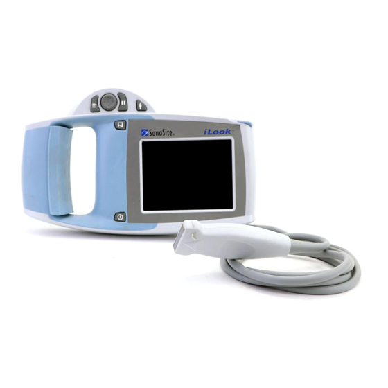
The following figure illustrates the iLook system. Transducer Handle pad Transducer clip Stylus Battery I/O connector Figure 1.1 The iLook System Table 1.1 The iLook System Item Description Battery Two batteries are provided. Fully depleted batteries require approximately two hours to charge to 90% capacity and three hours to charge to 100% capacity. -
Page 11: Conventions Used In This Manual
Software Licensing Use of software that you receive from SonoSite is controlled by a license key. A license key is a number sequence containing exactly 12 decimal digits. If you require a license key you will be notified by SonoSite. - Page 12 Service Manual...
-
Page 13: Chapter 2 Safety
Safety HAPTER Please read this information before using the iLook system. It applies to the ultrasound system, transducers, accessories, and peripherals. A Warning describes precautions necessary to prevent injury or loss of life. A Caution describes precautions necessary to protect the products. -
Page 14: Equipment Protection
To avoid the risk of electrical shock, use only accessories and peripherals recommended by SonoSite. Connection of accessories and peripherals not recommended by SonoSite could result in electrical shock. Contact SonoSite or your local representative for a list of accessories and peripherals available from or recommended by SonoSite. -
Page 15: Battery Safety
Caution: Remove the battery from the system if the system is not likely to be used for some time. Do not spill liquid on the system. The top membrane of a phantom is delicate and can be damaged if handled improperly. Use minimum force when coupling the transducer to a phantom. -
Page 16: Biological Safety
Perform ultrasound procedures prudently. Use the ALARA (as low as reasonably achievable) principle. SonoSite does not currently recommend a specific brand of acoustic standoff. Labeling Symbols Labeling symbols for SonoSite products can be found in the user guide for each product. iLook Service Manual... -
Page 17: Chapter 3 System Overview
System Overview HAPTER Theory of Operation The SonoSite ultrasound system has seven major functional groups: the transducer, the acquisition subsystem, the processing subsystem, the display subsystem, the control subsystem, the user interface subsystem, and the power subsystem. Figure 3.1 shows how these functions interact. -
Page 18: Transducer
The software user interface is the interaction between the user and the screen layout components. The form factor is the device’s physical attributes: buttons, location and grouping of buttons and the device size, shape, and weight. Dedicated controls, or often-used features, are grouped according to user workflow. iLook Service Manual... -
Page 19: Power Subsystem
Upon detecting a fault, the system disables the pulser supply, and signals an error to the control subsystem. The power subsystem includes the battery pack and the battery charging electronics. Components The SonoSite system components are identified in Section 1.1, About the System, on page Controls Figure 3.2... -
Page 20: Accessories
Use stylus to tap on-screen menu options, position calipers, Screen and enter data. The touch screen is not active during live imaging. Accessories For information about accessories and other SonoSite products, refer to the user guide for each product. 3.4.1 Battery Pack Caution: Use only the specified SonoSite battery pack. -
Page 21: Battery Charge Indicators
Table 3.2 Battery Pack Operation Specifications Battery Pack Operation Parameter Specification ° Operation time based on usage model: 20 min @ 25 In a 2-hour period, the projected conservative power usage model for the imaging physical use is as follows: •... -
Page 22: External System Connections
Caution: Use only the specified SonoSite power adapter. A universal power adapter (50–60 Hz, 85–264 VAC) powers the SonoSite system. When the system is placed in the docking station, which is plugged into a wall outlet, the battery pack recharges. Recharging a battery which is not fully discharged will not decrease battery life. -
Page 23: System Specifications
System Specifications This section provides specifications for the SonoSite ultrasound system. 3.5.1 Physical Dimensions Length: 6.4 in. (16.26 cm) Width: 10.85 in. (27.56 cm) Depth: 1.5 in. (3.81 cm) Weight: 2.8 lbs. (1.27 kg) with the C15 transducer and battery installed Weight: 2.8 lbs. -
Page 24: Temperature, Pressure, And Humidity Limits
(1) 15 VDC, 2 A Max (system; battery charging, spare) (2) 12.6 VDC, 0.8 A Max (battery charging, system) Stand Output: (1) 15 VDC, 2 A Max (system; battery charging) (2) 12.6 VDC, 0.8 A Max (battery charging, system) iLook Service Manual... -
Page 25: Battery
Committee on Radio Interference. Industrial, Scientific, and Medical (ISM) Radio- Frequency Equipment Electromagnetic Disturbance Characteristics-Limits and Methods of Measurement. The Classification for the Sonosite system, SiteStand, accessories, and peripherals when configured together is: Group 1, Class A. 3.7.3 Airborne Equipment Standards... - Page 26 Service Manual...
-
Page 27: Chapter 4 Setup And Operation
This feature prevents battery discharge, resulting from accidentally turning the system on. It also prevents accidentally turning the system off during an exam. The first time you turn on the system, set the date and time. See the iLook User Guide. Caution: Do not use the system if an error message appears on the image display. -
Page 28: Installing And Removing The Battery
Note: When the battery charge is depleted or the battery is replaced, the system retains brightness, contrast, auto shut off, language, video format, date/time, and patient information. iLook Service Manual... -
Page 29: Using Ac Power
Using AC Power The battery charges when the system is using AC power. If the system is off and connected to AC power, a fully discharged battery will charge in about three hours. To operate the system using AC power: Connect the line cord to the AC power adapter. -
Page 30: System License Keys
SonoSite Technical Support at 1-877-657-8118. If you encounter difficulty with the system, use the information in this chapter to help correct the problem. If the problem is not covered here, call SonoSite Technical Support at the following numbers or addresses: USA/Canada Customers •... -
Page 31: Displaying The System Information Screen
4.4.1 Displaying the System Information Screen To display the system information screen, see To view your license key: on page 4.4.2 Displaying the License Update Screen To display the license update screen: On the system information screen, select License. The license update screen displays. Perform the steps in Installing a License Key on page Figure 4.4 License Update Screen... -
Page 32: Checking And Charging The Battery
Charging In Docking Station Ready Ready The system will operate on a fully-charged battery for 20 minutes or more, depending upon use. Ensure the battery is charged at all times to provide the longest possible battery operation. iLook Service Manual... - Page 33 When the system is not likely to be used for some time, remove the battery from the system to prevent total battery discharge. To charge the battery: Caution: Charge batteries only when the ambient temperature is between 32° and 104°F (0° and 40°C). Connect the AC line cord of the AC power adapter to a hospital-grade electrical outlet.
- Page 34 Service Manual...
-
Page 35: Chapter 5 Cleaning And Disinfecting
Cleaning and Disinfecting HAPTER Universal Precautions SonoSite recommends that personnel who have regular exposure to medical devices returned for service practice “universal precautions.” Universal precautions are an approach to infection control. Those servicing this product should follow the prescribed standards for their area. -
Page 36: Recommended Disinfectants
SonoSite technical support or your local representative. For information about a specific product, call the product manufacturer. Recommended Disinfectants For a list of disinfectants recommended for use on the SonoSite ultrasound system and transducers, see the iLook User Guide. iLook Service Manual... -
Page 37: Hapter 6 Troubleshooting
Troubleshooting HAPTER System and Subsystem Diagnosis This section covers basic diagnostic and troubleshooting procedures you may need if the system does not operate properly. To diagnose system failures, consult Table 6.1 and the referenced diagnostic figures that follow. Table 6.1 Troubleshooting Subassemblies and Diagnostic Figures Subassemblies Diagnostic Figures Display... -
Page 38: Failures
The main PCBA can present symptoms that may be difficult to assess. Main PCBA failures result in “assert codes” that are output to the display. Note these assert codes and contact SonoSite technical support, per Appendix B, Service Event Report, on page 87, to clarify the failure. -
Page 39: Clearing The Main Pcba Failure
6.4.4 Clearing the Main PCBA Failure After the assert code has been recorded, power down the system. Remove the system from the docking station or the stand. Remove the battery. After the system has powered down, reinstall the battery. Turn the power back on to check if the fault cleared or if the condition remains. If the condition cleared, you may use the system. - Page 40 External Monitor To The Video Port Ext. Replace Monitor Main PCBA Corrected? Replace Display Return Replace Main Corrected? Corrected? System to PCBA SonoSite Perform Perform Perform Image Quality Image Quality Image Quality Tests Tests Tests Figure 6.2 Display Diagnosis iLook Service Manual...
- Page 41 Replace Correct External Monitor? Replace Connect Monitor Corrected? Main PCBA Cable Replace Cable Stop Corrected? Stop Corrected? Stop Replace Main PCBA Return Return System to System to Corrected? Stop SonoSite SonoSite Figure 6.3 External Monitor Diagnosis Chapter 6: Troubleshooting 33...
- Page 42 If A Key Or System Control Button Is Not Working Replace Display Assembly Replace Corrected? Main PCBA Return Corrected? System to SonoSite Stop Perform Image Quality Tests Figure 6.4 Control Panel Diagnosis iLook Service Manual...
- Page 43 Working? Supply Replace Replace Main PCB Main PCB Perform Perform Image Quality Image Quality Tests And Tests And Corrected? Corrected? Verify Power Verify Power Supply Supply Operation Operation Return System To SonoSite Figure 6.5 System Diagnosis Chapter 6: Troubleshooting 35...
- Page 44 Battery and Fully Inserted? Connect Try Again Power Supply Insert Go To System Battery and Diagram Try Power Again Working? System OK Charge or Replace Battery Working? System OK Go To System Diagram Figure 6.6 Battery Diagnosis iLook Service Manual...
-
Page 45: Chapter 7 Replacement Procedures
Display Subassembly Replacement Note: Consult Section 6, Troubleshooting, on page 29 before making any repairs. 7.1.1 Required Parts Service Assembly, Display, iLook (P03038) 7.1.2 Required Tools and Materials • A #1 Phillips screwdriver, 7.0 in. (17.8 cm / 177.8 mm) •... -
Page 46: Removing The Display Subassembly
The transducer cable strain relief and plastic insert will drop off of the system. (Figure 7.5) Retain these parts, they will be used to reassemble the system. Do not remove the battery cable from the Main PCBA. iLook Service Manual... - Page 47 3/32" hex screw 6 Phillips screws Figure 7.1 Display Side Down Display cables Figure 7.2 Display Cables Chapter 7: Replacement Procedures 39...
- Page 48 Wired connector Figure 7.3 Wired Connector Battery cable 5 3/32" hex screws Figure 7.4 Hex Screws and Battery Cable iLook Service Manual...
-
Page 49: Replacing The Display Subassembly
Display cable Panel clip Plastic insert Strain relief Battery cable Figure 7.5 Display Cable Exposed 7.1.4 Replacing the Display Subassembly Place the Main PCBA on the anti-static surface with the transducer connector towards you and facing up. (Figure 7.5) Attach the display cable to the connector making sure it is seated firmly into the connector before pressing the locking mechanism into place. - Page 50 (Figure 7.1) 12 Place the battery in the battery compartment. 13 Turn on the system. 14 Perform the Display tests in Chapter 8, Performance Tests, on page 63, to verify that the Display Subassembly is functioning properly. iLook Service Manual...
-
Page 51: Transducer Subassembly Replacement
Transducer Subassembly Replacement 7.2.1 Required Parts • Service Assembly, C15 Transducer, iLook (P03040), or • Service Assembly, L25 Transducer, iLook (P03157) Caution: Transducers are not interchangeable. Make certain you have the correct transducer or your system will not function. 7.2.2 Required Tools •... - Page 52 10 Separate the transducer from the Main PCBA by removing the plastic panel clip and gently pulling the transducer connector PCB from the Main PCBA. (Figure 7.7) Panel clip Transducer PCBA Figure 7.7 Transducer Separated from Main PCBA iLook Service Manual...
-
Page 53: Replacing The Transducer Subassembly
7.2.4 Replacing the Transducer Subassembly Attach the transducer to the Main PCBA by attaching the transducer connector PCB to the Main PCB Connector. (Figure 7.7) Install the plastic panel clip to hold the cable in place. (Figure 7.7) Place the Main PCBA on the anti-static surface with the transducer connector towards you and facing up. -
Page 54: Rear Case With Label Subassembly Replacement
Rear Case with Label Subassembly Replacement 7.3.1 Required Parts Service Assembly, Rear case with label, iLook (P03041) 7.3.2 Required Tools • A #1 Phillips screwdriver, 7.0 in. (17.8 cm / 177.8 mm) • A 3/32" hex driver • A torque driver, 2.0–10.0 in./lb. (0.2–1.1 newton meter) •... -
Page 55: Main Pcba Subassembly Replacement
Main PCBA Subassembly Replacement 7.4.1 Required Parts • Service Assembly, Main PCBA, iLook15 (P03039), or • Service Assembly, Main PCBA, iLook25, (P03156) Caution: Main PCBAs are not interchangeable. Make certain you have the correct subassembly for your system or it will not operate. 7.4.2 Required Tools •... -
Page 56: Replacing The Main Pcba Subassembly
Install the five (5) 3/32" hex screws that hold the PCBA in place. Torque the screws to 3.4 in/lb. (Figure 7.4) Install the plastic insert and the transducer cable strain relief. (Figure 7.6) Insert the two (2) 3/32" hex screws into the strain relief and tighten to 3.4 in/lb. (Figure 7.4) iLook Service Manual... -
Page 57: Ilook Docking Station Assembly
During the Warranty period, or under Extended Service Support, customers who experience Docking Station failures will receive an exchange product by overnight shipping. Contact the SonoSite Technical Support Department for immediate service. Outside of the Warranty period the Docking Station Assembly may be repaired by ordering and replacing any of the parts identified in Section A.10, Docking Station... -
Page 58: Ilook Docking Station Disassembly And Reassembly
7.5.1 iLook Docking Station Disassembly and Reassembly Turn the Docking Station upside down. Remove the seven (7) Phillips head screws identified in Figure 7.10. Phillips screws Figure 7.10 Docking Station Screws Hold the top cover in place and gently turn the complete assembly over so it sits on the base. -
Page 59: Ilook Docking Station/Stand Theory Of Operation
Figure 7.12 Docking Station Head Screws Assemble the Docking Station by following steps 1-8 in reverse order. 7.5.2 iLook Docking Station/Stand Theory of Operation Main Battery Status LEDs and I/O Control The System communicates with the Docking Station and Stand via the I2C Interface. - Page 60 VIL = 0.46V SYS_SENSEN 2.74K SYSTEM POW ER ADAPTER CABLE VCHG BATTERY +3.3V 47.5K DOCK_SENSEN FPG A SYS_SENSEN SYSTEM STAND VCHG BATTERY +3.3V 47.5K +3.3V DOCK_SENSEN FPG A VIH = 2.8V SYS_SENSEN Figure 7.13 Docking Station/Stand/Power Adapter Cable Sense iLook Service Manual...
- Page 61 Table 7.9 for pin assignments. Dock Connector PCB Pin 1 To Dock Docking To iLOOK Main Flat Flex Cable Connector ZIF Connector Figure 7.14 Docking Station Connector PCB Assembly Docking Station and Stand PCB Assemblies The Docking Station and Stand PCBs are four layer boards with components on Layer 1, traces on Layers 2 and 3 and ground plane on the bottom.
- Page 62 Spare Battery RS232 Power Dock Conn Main Spare LEDs LEDs Figure 7.15 Docking Station Board Outline and Connector Placement POWER SYSTEM RS-232 PRINT CONTROL VIDEO Figure 7.16 Stand Board Outline and Connector Placement iLook Service Manual...
- Page 63 Power Adapter Cable A wiring Diagram for the Power Adapter Cable is shown in Figure 7.17. +15V +15V VBAT- +15V RATE VCHG PWR_RET VCHG VBAT- DOCK_SENSEN SYS_SENSEN Looking into receptacle VIDEO Figure 7.17 Power Adapter Cable Wiring Diagram Connector list Pin assignments for each of the connectors are given in the following tables: Table 7.3 Video Connector Pin Assignments Signal...
- Page 64 Data transmitted from iLook to connected device. Signal ground. Request to Send from iLook to connected device. Clear to Send received by iLook from connected device. DCD, DTR, DSR, RI 1, 4, 6, 9 Modem control signals not used or driven by iLook.
- Page 65 P2-19, 21 P1-15 Video Return. Isolated from Docking Station Power_Return. VIDEO P7-20 P2-20 P1-16 Composite Video from iLook to Docking Station connected device. PWR_RET P7-1, 11, P2-1, 11, P1-8, 17, AC/DC Adapter Power Return on Connector Shield and Mounting Pins. Isolated from Docking Station Signal Ground.
- Page 66 Schematic Diagram Figure 7.18 Schematic Diagram iLook Service Manual...
-
Page 67: Ilook Stand Assembly Service
During the Warranty period, or under Extended Service Support, customers who experience Stand failures will receive an exchange product by overnight shipping. Contact the SonoSite Technical Support Department for immediate service. Outside of the Warranty period the Docking Station Assembly may be repaired by ordering and replacing any of the parts identified in Section A.10, Docking Station... -
Page 68: Ilook Stand Docking Section Disassembly And Reassembly
7.6.1 iLook Stand Docking Section Disassembly and Reassembly Remove the three (3) 1/8" hex screws from the top of the stand. Set the transducer holder aside and place the cradle assembly on a static free surface. (Figure 7.20) Cradle assembly 1/8"... - Page 69 #1 Phillips screws Docking station connector assembly Flex cable #1 Phillips screws Figure 7.22 PCBA Reassemble the docking assembly by following the above steps in the reverse order. Chapter 7: Replacement Procedures 61...
-
Page 70: Ilook Stand Theory Of Operation
7.6.2 iLook Stand Theory of Operation The iLook Stand Theory of Operation is included in Chapter 7.5.2, iLook Docking Station/Stand Theory of Operation. Schematic diagram. See Figure 7.23. Figure 7.23 Theory of Operation Schematic iLook Service Manual... -
Page 71: Chapter 8 Performance Tests
Verify that all controls operate smoothly over their full range and that the system responds properly. To obtain 2D images, SonoSite recommends using the RMI 413A Soft Tissue Phantom or, the RMI 403 GS Multipurpose Phantom. Any equivalent Phantom is acceptable. -
Page 72: Setting Up Performance Tests
Verify that the ultrasound image appears uniform in both the axial and lateral direction, with no dropouts or intensity variations. Verify that the cystic structure at the focal zone is clearly differentiated from the surrounding tissue and is echo-free, while solid tissue, with numerous echo sources, appears solid. iLook Service Manual... -
Page 73: Axial Measurement Accuracy
8.4.2 Axial Measurement Accuracy Note: Measurements must be performed while the image is frozen. To test axial accuracy: Acquire the image. Press Freeze. Select Meas to measure. Two calipers appear on the image display. A menu appears, on which are listed two caliper buttons. (A dotted line connects the two calipers.) The first caliper Cal 1, in the menu is active by default. -
Page 74: Lateral Measurement Accuracy
8.2. Measure from the center of the skinline to the deepest vertical position—where the scatter echoes start to break up and tissue definition is lost. Table 8.2 Imaging Performance Imaging Performance 2D Penetration 19.0 cm 6.0 cm iLook Service Manual... -
Page 75: Additional Performance Tests
To test CPD: Note: Use the RMI 425 Doppler Phantom or the RMI 1425A Doppler Phantom. Set up the system for CPD mode. Set iLook 15 exam type to ABD. Acquire the image. Press and release the menu key and use the directional controller to select CPD mode. -
Page 76: Tissue Harmonic Imaging (Thi) (Ilook 15 Only)
Verify that no flow exists outside the vessel. Save a DCPD image by pressing Freeze and then Save. 8.5.3 Tissue Harmonic Imaging (THI) (iLook 15 only) To test Tissue Harmonic Imaging: Set up the system for THI mode. Acquire the image. -
Page 77: Printer
8.5.6 Printer To test printer operation: Print two images in rapid succession and verify proper operation. Verify that the print control button on the printer functions correctly. 8.5.7 Battery Charging To test battery charging operation: Insert a battery into the system. Set the system onto a docking station assembly. Note: The stand assembly does not have LEDs and the battery charging cannot be tested on the stand. -
Page 78: Touch Screen Calibration
Select or tap Yes. The first calibration screen will appear. (Figure 8.4) Tap the center of the crosshairs. The second calibration screen will appear. (Figure 8.5) Tap the center of the crosshairs. The calibration confirmation appears. (Figure 8.6) 10 Tap the center of the crosshairs. iLook Service Manual... - Page 79 Figure 8.4 First Calibration Screen Figure 8.5 Second Calibration Screen Figure 8.6 Calibration Confirmation Screen Chapter 8: Performance Tests 71...
-
Page 80: Returning Products To Sonosite
13 When the calibration is successful select or tap Done twice and select or tap Exit to return to 2D scanning. Returning Products to SonoSite 8.6.1 Contacting SonoSite Technical Support For technical support of any SonoSite product, do one of the following: • U.S. and Canadian customers, call 1-877-657-8118. • International customers, call +425-951-1330. -
Page 81: Parts List
Parts List PPENDIX Replacement Parts List The following tables contain all the replaceable parts for the SonoSite ultrasound system. All quantities are one unless otherwise noted. Ordering Replacement Parts To order parts, contact SonoSite Technical Support as indicated in Section 8.6,... - Page 82 Part Number Description P03038 Service Assembly, Display, iLook Display Subassembly Parts List Note: This part is sold as a complete assembly. If you choose to attempt repairs to your assembly the warranty is void. Contact technical support to identify the failed component and order it from the list below.
- Page 83 Table A.1 Display Subassembly (Continued) P02435 Label, Display P02436 Cable, FFC, 0.5mm pitch, 18 pos P02437 Wire Harness, Back Light Inverter P02612 Screw, K25 x 6, panhead P02613 Screw, K35 x 10, panhead P02847 Cable, FFC, 1.0mm pitch P02879 Insulator, Probe, PCB P02910 Screw, Panhead, Phillips, 6-32 x .25 Appendix A: Parts List 75...
- Page 84 Transducer Subassembly Table A.2 Transducer Subassembly Find Number Part Number Description P03040 Service Assembly, C15 Transducer, iLook P03157 Service Assembly, L25 Transducer, iLook iLook Service Manual...
- Page 85 Rear Case with Label Subassembly Table A.3 Rear Case with Label Subassembly Part Number Description P03041 Service Assembly, rear case with label Note: When ordering this part provide the REF Number and Serial Number from the damaged product. The part will be shipped with a new label. Appendix A: Parts List 77...
- Page 86 Table A.4 Main PCBA Find Number Part Number Description P03039 Service Assembly, Main PCBA, iLook, C15 P03156 Service Assembly, Main PCBA, iLook, L25 Note: These PCBAs are very similar. Be sure to order the correct PCBA for your product. iLook Service Manual...
- Page 87 Power Supply Table A.5 Power Supply Part Number Description P01139 Power Supply, iLook Appendix A: Parts List 79...
- Page 88 Cables Table A.6 Cables Find Number Part Number Description P00537 Control Cable, Printer P01568 Cable, Serial, Null Modem P01111 Video Cable (RCA/RCA) P00536 Video Cable, Printer (RCA/BNC) P02803 Cable, Auxiliary Power iLook Service Manual...
- Page 89 Additional Spare Parts Table A.7 Additional Spare Parts Find Number Part Number Description P02220 Insert, Hand Padding, Thick P02407 Insert, Hand Padding, Thin P02221 Clip, Probe, C15 P02183 Stylus P02935 Clip, Panel, Key hole P03069 Brace, Latch, L25 Appendix A: Parts List 81...
- Page 90 A.10 Docking Station Assembly 2 (on bottom) (on bottom) 7 & 9 Table A.8 iLook Docking Station Spare Parts Find Number Part Number Description P02396 Enclosure, Bottom, Docking Station P00976 Bumper, Elastomeric P02345 Assembly, PCB, Docking Station P02855 Screw, Panhead, Phillips, 4-40...
- Page 91 Table A.8 iLook Docking Station Spare Parts (Continued) P02399 Grommet P02445 Cradle, Docking Station P02881 Screw, shoulder, Phillips 4-40 P00135 Screw, K35 x 12, panhead, Phillips (not shown) P02395 Enclosure, Top, Docking Station P02347 Assembly, PCB, Docking Station Connector P02958...
- Page 92 A.11 iLook Stand iLook Service Manual...
- Page 93 Table A.9 iLook Stand Spare Parts Find Number Part Number Description P02347 Assembly, PCB, Docking Station Connector P02847 Cable, FFC P03029 Assembly, PCB, Stand P03067 Base, Docking Station P03144 Base, Stand P03178 Assembly, Tilt Clamp P03064 Bracket, Pivot, Main P03065...
- Page 94 Service Manual...
- Page 95 The Service Event Report provides information about product failures to the manufacturer and to authorized service facilities, which provide approved warranty services for SonoSite products. For all repairs completed, complete the form and return a copy of it to the following address: SonoSite, Inc.
- Page 96 Service Event Report Service Provider Name: Date: Company: Address: Phone Number: Fax Number: E-mail address: Device Description Name: Serial Number: Part Number: Lot Number: Revision: Software Version: Other Identifiers: Event Description Diagnosis Service Performed Performed By: Date: Actions: Parts Removed Part Name Part Number Serial Number...
- Page 97 Index Numerics control panel assembly removing, 43 2D imaging, 1 replacing, 45 2D performance tests required parts, 43 required tools, 43 axial measurement accuracy, 65 image quality, 64 control subsystem, 10 lateral measurement accuracy, 66 controls penetration, 66 system, 11 conventions, 3 CPD imaging, 1 AC power...
- Page 98 77 description, 12 patient, description, 12 service event report, 87 performance tests, 63–72 form, 88 overview, 63 setup and operation, 19 peripheral output, 69 printer, 68 shipping required test equipment, 63 instructions, 72 video output, 69 iLook Service Manual...
- Page 99 SiteCharge dual battery charger, 51, 62 theory of operation, 9–11 SiteLink Image Management software, 1 touch screen software description, 12 licensing, 3 trackball assembly SonoSite technical support removing, 46 contacting, 72 required parts, 46 standards required tools, 46 airborne equipment, 17 transducer, 15...
- Page 100 Service Manual...
Need help?
Do you have a question about the iLook and is the answer not in the manual?
Questions and answers