
Subscribe to Our Youtube Channel
Related Manuals for Euroboor ECO.50?T


Summary of Contents for Euroboor ECO.50?T
- Page 1 EUROBOOR FOR PROFESSIONALS BY PROFESSIONALS INSTRUCTION MANUAL ECO.50‐T Magnetic Drilling Machine SERIAL NO.____________ DATE OF PURCHASE __________...
- Page 2 Congratulations on your purchase of the Euroboor ECO.50‐T Portable Magnetic Drilling Machine. Your model is designed to produce superior holes quickly and efficiently. Through years of experience, constant innovation and development, Euroboor BV is committed to provide you with metal cutting tools and products to help you be more productive. Before operating your new magnetic drilling machine, please read all instructions first. These include the Operator’s Manual and Warning Label on the unit itself. With proper use, care, and maintenance, your model will provide you with years of effective hole drilling performance. TO REDUCE THE RISK OF INJURY USER MUST READ AND UNDERSTAND ALL INSTRUCTIONS EUROBOOR BV Kryptonstraat 110 2718 TD Zoetermeer Netherlands T +31 79 361 49 90 F +31 79 361 49 89 info@euroboor.com www.euroboor.com ISSUE 1/Original version/OCT 2013 2 2 ...
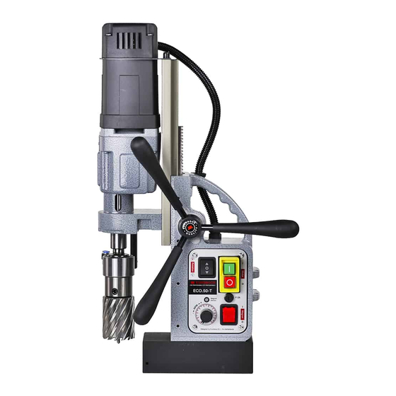
- Page 3 Fig. 1 ISSUE 1/Original version/OCT 2013 3 3 ...
- Page 4 Symbol Term, meaning Explanation Be absolutely sure to read the enclosed Read documentation documentation such as the Instruction Manual and the General Safety Instructions. Wear ear protection Use ear protection during operation. Wear eye protection Use eye‐protection during operation. Danger/warning/caution Observe the information in the adjacent text! European conformity symbol Confirms the conformity of the power tool with the directives of the European Community. Product with basic insulation and exposed Class of protection I (touchable), conductive parts additionally connected to the protective earth conductor. mm ...
-
Page 5: General Power Tool Safety Warnings
GENERAL POWER TOOL SAFETY WARNINGS Do not use this power tool before you have thoroughly read and completely understood this Instruction Manual and the “General Safety Instructions”, including the figures, specifications, safety regulations and the signs indicating DANGER, WARNING and CAUTION. WARNING: When using electrical tools basic safety precautions should always be followed to reduce the risk of fire, electrical shock and personal injury including following. Please also observe the relevant national industrial safety regulations. Non‐observance of the safety instructions in the said documentation can lead to an electric shock, burns and/or severe injuries. This Operator’s Manual and the “General Safety Instructions” should be kept for later use and enclosed with the power tool, should it be passed on or sold. WORK AREA 1. Keep your work area clean and well lit. Cluttered benches and dark areas invite accidents. 2. Do not operate magnetic drilling machine in explosive atmospheres, such as in the presence of flammable liquids, gases or dust. Magnetic drilling machine may create sparks which may ignite the dust or fumes. 3. Keep bystanders, children, and visitors away while operating a magnetic drilling machine. Distractions can cause you to lose control. ELECTRICAL SAFETY 1. Magnetic drilling machine plugs must match the outlet. Never modify the plug in any way. Do not us any adapter plugs. 2. Avoid body contact with grounded surfaces such as pipes, radiators, ranges and refrigerators. There is an increased risk of electric shock if your body is grounded. 3. Do not expose magnetic drilling machines to rain or wet conditions. Water entering a machine will increase the risk of electric shock. 4. Do not abuse the cord. Never use the cord to carry the magnetic drilling machine or pull the plug from an outlet. Keep cord away from heat, oil, sharp edges or moving parts. Replace damaged cords immediately. Damaged cords increase the risk of electric shock. ... - Page 6 Caution, the slug may be hot! 3. Use clamps or other practical way to secure and support the work piece to a stable platform. Holding the work by hand or against your body is unstable and may lead to loss of control. 4. Do not use machine if switch does not turn it on or off. Any tool that cannot be controlled with the switch is dangerous and must be repaired. 5. Disconnect the plug from the power source before making any adjustments, changing accessories, or storing the tool. Such preventive safety measures reduce the risk of starting the tool accidentally. 6. Store idle Magnetic drilling machines out of reach of children and other untrained persons. Tools are dangerous in the hands of untrained users. 7. Maintain machines with care. Keep cutting tools sharp and clean. Properly maintained tools, with sharp cutting edges are less likely to bind and are easier to control. 8. Check for misalignment or binding of moving parts, breakage of parts, and any other condition that may affect the machine operation. If damaged, have the tool serviced before using. Many accidents are caused by poorly maintained tools. 9. Use only accessories that are recommended by Euroboor BV for your model. Accessories that may be suitable for one machine, may become hazardous when used on another machine. SERVICE Tool service must be performed only by qualified repair personnel. Service or maintenance performed by unqualified personnel could result in a risk of injury. When servicing a tool, use only identical replacement parts. Follow instructions in the Maintenance section of this manual. Use of unauthorized parts or failure to follow Maintenance Instructions may create a risk of electric shock or injury. When using this machine, you MUST wear ear and eye protection. ISSUE 1/Original version/OCT 2013 6 6 ...
-
Page 7: Residual Risks
ADDITIONAL SPECIFIC SAFETY RULES FOR MAGNETIC DRILLING MACHINES • Keep your fingers well out of the drill area; • Avoid touching the drilled core that is automatically ejected by the centering pin when the working procedure is finished. Contact with the core when it is hot, or if it falls, can cause personal injuries; • Always use the drill guard. Before turning on machine ensure the guard is closed securely; • Always use the safety strap; • The magnetic drilling machine is suitable for use on steel with a thickness starting from 6 mm, with zero air gap between the magnet core surface and the mounting surface. Curvature, coats of paint and surface irregularities will create an air gap. Keep the air gap to a minimum; • Always place the machine on a flat surface; Do not clamp the magnetic drilling machine on small or irregularly shaped objects; • Always place the machine on a surface that is clear of shavings, chips, swarf and surface dirt; • Keep the magnet clean and free of debris and swarf; • Do not turn on the machine until it has been mounted and installed according to these instructions; • Do not turn on the machine before having checked that the magnetic stand has been tightened firmly to the mounting surface; • Adjust the table so cutter does not extend into the work piece before drilling. Do not perform any design, assembly or construction activities on the work piece while the machine is turned on; • Before turning on the machine, make sure the accessory has been mounted correctly; • Always use the recommended speed for the accessories and the material; • Do not use the machine on the same work piece on which electric welders are being used; •... -
Page 8: Package Content
MARKINGS ON THE TOOL The following pictograms are shown on the tool: Read instruction manual before use. Wear ear protection in areas with noise emissions > 80 db(A). Wear eye protection. POSITION Serial number The Serial Number, which also includes the type of machine, the year and month of manufacturing and identification number, is engraved on the frame, magnet and the motor unit. Example: 050T 12 11 001 Model type Year of Manufacture Month of manufacture Identification number PACKAGE CONTENT 1 Magnetic drilling machine 4 Tap collets M10 DIN 376, M12 DIN 376, M14 DIN 376, M16 DIN 376 1 Carrying case 1 Drill guard 3 Handles 1 Allen Key 2.5 1 Allen Key 3 1 Allen Key 4 1 Allen Key 5 1 Wrench 8 ... -
Page 9: Total Power
TECHNICAL DATA ECO.50‐T ANNULAR CUTTERS ø 12 ‐ 50 mm TWIST DRILLS ø 1 ‐ 23 mm THREADING M3 ‐ M16 COUNTERSINKING ø10 ‐ 40 mm LENGTH 245 mm WIDTH 160 mm HEIGHT 385 ‐ 550 mm STROKE 170 mm WEIGHT 14 kg MAGNET (L x W x H) 170 x 85 x 48 mm MAGNETIC FORCE ... -
Page 10: Description (Fig. 1)
DESCRIPTION (fig. 1) WARNING: Never modify the power tool or any part of it. Damage or personal injury could result. 1. Safety Guard 2. Feed handle 3. Cooling system tank 4. Magnetic stand 5. Magnet switch 6. Motor switch INTENDED USE This magnetic drilling machine is intended for commercial use as a drilling machine for drilling materials with a magnetizable surface using annular cutters and twist drills, and for tapping, countersinking and reaming in a weather‐protected environment using the application tools and accessories recommended by EUROBOOR. The magnetic drilling machine can be used horizontally, vertically or overhead. INSTRUCTIONS FOR PUTTING INTO OPERATION Please make sure that the contacting surface for the magnet is level, clean and rust‐free. Remove any varnish or primer. When working on materials that are not magnetizable, suitable fixation devices, obtainable as accessories from EUROBOOR, e. g. suction plate, vacuum plate or pipe‐drilling device must be used. When work on steel materials with a material thickness of less than 12 mm, the work piece must be reinforced with an additional steel plate in order to guarantee the magnetic holding power. Check the machine for possible damage; Before using the machine, you must carefully check protective devices or slightly damaged components to ensure they are operating perfectly and as intended. Check that moving are in perfect working order and do not jam and check whether parts are damaged. All parts must be correctly installed and fulfill all conditions necessary to ensure perfect operation of the machine. Damaged protective devices and parts must be repaired or replaced according to specifications by ... -
Page 11: Assembly And Adjustments
2. Fit the screws into the hole located in the side of the magnet. WARNING: Always use the Safety guard. FITTING THE LUBRICATION SYSTEM (FIG. 1) The lubrication system can be used for horizontal drilling applications (the drill being used vertically). Hold the cooling tank against the bracket on the slide and push it in its place. Connect the hose to the nipple on the spindle drive shaft. In order to use the lubrication system, it must be filled with a sufficient amount of cutting fluid. 1. Make sure the flow regulator is closed; 2. Unscrew the cap; 3. Fill the container with cutting fluid; 4. Screw the cap back on. WARNING: Do not use the lubrication system in vertical or overhead drilling applications. Instead use Euroboor cutting paste FITTING THE SAFETY CHAIN 1. Pass the safety chain through the opening near the grip; 2. Wrap the chain around the work piece; 3. Securely close the chain using the lock. WARNING: Always use the safety chain when using machine vertically and/or up‐side‐down. ISSUE 1/Original version/OCT 2013 11 11 ... -
Page 12: Prior To Operation
WARNING: To reduce the risk of serious personal injury, turn tool off and disconnect tool from power source before making any adjustments or removing/installing attachments or accessories. MAGNETIC BASE Material of minimum 10 mm thickness is required for the magnet to work the best. The attachment force generated by the magnet depends on various factors. Thickness of the material the magnet is placed on; Paint or coating of the material the magnet is placed on; Metal chips, oil or other dirt under the magnet. If the LED indicator (see page 13) lights up GREEN, the magnet is generating sufficient attachment force. If the LED indicator lights up RED, the magnet may not generating sufficient attachment force. WARNING: Do not use this machine when LED indicator is RED. Magnet may not generate sufficient attachment force We would like to point out that this is only an indication and not a certainly that the magnet will not release from the material. Euroboor accepts no liability ensuring from the magnet indicator not functioning or functioning poorly. Make sure that the magnet attaches tightly to the work piece before turning on the motor unit of the magnetic drilling machine. Euroboor magnets have 2 coils; make sure that both coils are in contact with the material. Do not connect any other machines to the electrical outlet the magnetic drilling machine is plugged into, as it may result in the loss of magnetic force. Always use the safety chain included. Drilling above your head is extremely dangerous and is not recommended. For the use of magnetic drilling machines on pipes, not‐flat or non‐magnetic materials, we refer to our brochure or our website www.euroboor.com where several vacuum tightening systems and pipe clamping systems are mentioned. ISSUE 1/Original version/OCT 2013 12 12 ... -
Page 13: The Control Panel
The control panel on your magnetic drilling machine is designed for maximum operating facility and safety. 1. The L/R Switch: This switch controls the direction of the motor unit. 2. The Motor Switch: This switch is used to switch the motor unit ON and OFF; 3. The Magnet LED Indicator: This LED indicator shows the generated magnetic force; 4. The Fuse holder with Fuse: This Fuse holder is included on every Euroboor Magnetic Drilling Machine and holds the fuse type : 5x20, F2A. Fig. 2 5. The Potentiometer: This controls the running speed of the motor unit. Note: A lower position will decrease the power of the motor unit. 6. The Magnet Switch: This switch is used to switch the main power and also the magnet On and Off. This switch is included on every Euroboor magnetic drilling machine In order to operate properly, the machine has to be turned on following the procedure as described below. ACTIVATING THE MAGNET ... - Page 14 TEMPERATURE The ECO.50‐T is equipped with an all‐time electronic temperature protection. If the temperature of the motor unit runs up to 70 Degree Celsius the motor unit will stop. After a few minutes it can be started again and we recommend running the motor unloaded with the electronic speed adjustment set on 100% in order to let the motor unit cool down. DRILLING A HOLE Now that you have read the explanatory information and safety recommendations above, you are ready to actually start drilling. Follow these 10 steps for best drilling result : Use the tip of the pilot pin to determine the center of the hole to be drilled. Turn the magnet on and verify that the drill is in the right position and that the machine is pushed tight against the work piece. If your machine is equipped with a auto coolant system, put open the valve to release the oil. If your machine does not have a auto coolant system, fill the holes of the spindle with oil. 4 Turn the motor on at the highest setting and allow it to run at full speed. 5 Turn the arms to start drilling. Apply only a slight pressure when the Annular Cutter touch the metal. Do not push the Annular Cutter with force into the metal. 6 Apply a regular pressure while drilling. The drilling performance does not improve by putting more pressure on the tool. Too much pressure will overload the motor and your Annular Cutter will be worn sooner. Let the cutter do the job and give it time to cut the metal!!! 7 Adjust the oil supply when necessary, if your drill does not have a auto coolant system, stop drilling regularly, refill the holes of the spindle and continue drilling. 8 Apply less pressure when the drill cuts through the material. 9 Turn the arms to put the motor in highest position and turn off the motor unit. ...
- Page 15 DRILLING CONDITIONS The ease with which material can be drilled depends on several factors including tensile strength and abrasion resistance. Whilst hardness and/or strength is the usual criterion, wide variations in machineability can exist among material showing similar physical properties. The drilling conditions are dependent on requirements for tool life and surface finish. These conditions are further restricted by the rigidity of the tool and the work piece, lubrication and machine power available. The harder the material, the lower the cutting speed. Some materials of low hardness contain abrasive substances leading to rapid cutting edge wear at high speeds. Feed rates are governed by rigidity of set‐up, volume of material to be removed, surface finish and available machine power. THREADING The machine is equipped with a reversible direction of rotation and can also be used for cutting threads. Proceed as follows for cutting threads: Drill the hole for the thread on the recommended size of the tap; Switch off the machine (Fig. 2‐2) and change the cutter for the tap collet and the machine tap. Keep the machine in the same position; Select the lowest gear (Fig. 4) and lowest speed (Fig. 2‐5) and set the direction of rotation to clockwise (right = R) at switch (Fig. 2‐1); Switch on (Fig. 2‐2) the machine and set the machine tap onto the drilled hole; Guide the machine slide down at the handle (Fig. 1‐2) without exerting; Switch off (Fig. 2‐2) the machine (just before the tap is completely through the hole) and set the direction of rotation to anti‐clockwise (left = L) at switch (Fig. 2‐1). Switch on the machine (Fig. 2‐2) again and allow the machine tap to come completely out of ...
- Page 16 Add more cutting fluid if the shavings (metal chips) become blue. VERTICAL AND OVERHEAD APPLICATIONS Dip the cutter in cutting paste or apply an appropriate spray. LUBRICATING THE FEED TRAVEL The feed travel should be lubricated periodically with grease to ensure smooth operation. Raise the motor unit to the highest position possible; Lubricate the dove‐tail guide way at both sides; Lubricate the gear rack. After repeated use, the gear rack may become loose. If necessary, adjust the 5 self‐locking set screws at the left side. Tighten screws in series until the gear rack moves freely in the dove‐tail guide but does not allow the motor to wobble. Cleaning WARNING: Blow dirt and dust out of the main housing with dry air as often as dirt is seen collecting in and around the air vents. Wear approved eye protection and approved dust mask when performing this procedure. WARNING: Never use solvents or other harsh chemicals for cleaning the non‐metallic parts of the tool. These chemicals may weaken the materials used in these parts. Use a cloth dampened only with water and mild soap. Never let any liquid get inside the tool; never immerse any part of the tool into a liquid. Optional Accessories WARNING: Since accessories, other than those offered by EUROBOOR, have not been tested with this product, use of such accessories with this tool could be hazardous. To reduce the risk of injury, only EUROBOOR recommended accessories should be used with this product. Consult your dealer for further information on the appropriate accessories. ISSUE 1/Original version/OCT 2013 16 16 ...
-
Page 17: Maintenance
MAINTENANCE Your EUROBOOR power tool has been designed to operate over a long period of time with a minimum of maintenance. Continuous satisfactory operation depends upon proper tool care and regular cleaning. CAUTION: To reduce the risk of injury, turn unit off and disconnect machine from power source before installing and removing accessories, before adjusting or changing set‐ ups or when making repairs. Be sure the switch is in the OFF position. An accidental start‐up can cause injury. Just as every magnetic drilling machine with moving parts, your Euroboor magnetic drilling machine also needs regular maintenance service. A few recommendations follow : VISUALLY CHECK THE MACHINE FOR DAMAGE Machine must be checked before operation for any signs of damage that will affect the operation of the machine. Particular notice must be taken of the mains cable, if the machine appears to be damaged it should not be used failure to do so may cause injury or death. CAUTION : Clean all dirt, dust, metal chips and burrs of your magnetic drilling machine OPERATION OF THE MACHINE The machines operation must be checked to ensure that all components are working correctly. Replace any defective parts immediately. This prevents properly function parts from being damaged. CARBON BRUSHES Brushes should be checked to make sure there is no abnormal wear present. This should be checked at least once a week if used frequently. If the carbon brush has worn more than 2/3 the original length the brushes should be changed. Failure to do so may cause damage to the machine. CHECK MAGNETIC BASE Before every operation the magnetic base should be checked to make sure that the base is flat and there is no damage present. An uneven magnet base will cause the magnet not to hold as efficiently and may cause injury to the operator. CHECK MACHINES GREASE The gearbox grease should be checked once a month to ensure all moving components are covered to prevent wear. The grease should be changed at least once a year to ensure you gain the best from the machine. CHECK ARMATURE ... - Page 18 ADJUSTMENT OF SLIDE An essential requirement of the machine is that the slide can move in a smooth and controlled manner, free of lateral movement and vibration. This situation can be maintained by periodic adjustment of the slide and is accomplished in the following manner: 1. Place the machine in an upright position and, by means of the capstan, raise the slide to its highest position. Clean the brass rail strips and apply a small amount of light machine oil to the wear surfaces. 2. Commencing with the top screw, loosen both setting nut (#4 on spare part drawing) with included wrench 8 and the setting screw (#5 on spare part drawing) with included Allen key 2.5. Then gently feed in setting screw until slight resistance is encountered. Follow your way down adjusting all setting nuts and screws. 3. Operate the slide up and down a few times to test the movement and make any further necessary adjustments. Try to ensure that all the screws are exerting a uniform pressure on the slide from top to bottom. A perfectly adjusted slide will operate freely up and down without any sideways movement. REPAIR, MODIFICATION AND INSPECTION Repair, modification and inspection of Euroboor Magnetic drilling machines must be done by EUROBOOR or an EUROBOOR authorized dealer. The spare parts list will be helpful if presented with the machine to the Euroboor dealer for service when requesting repair or other maintenance. Euroboor machines are constantly being improved and modified to incorporate the latest technological advancements. Accordingly, some parts (i.e. part numbers and/or design) may be changed without prior notice. Also, due to Euroboor's continuing program of research and development, the specifications of machines are subject to change without prior notice. ISSUE 1/Original version/OCT 2013 18 18 ...
-
Page 19: Troubleshooting
TROUBLE SHOOTING Magnet and motor do not ‐ The magnet switch is not connected to the power supply function ‐ Damaged or defective wiring ‐ Defective fuse ‐ Defective magnet switch ‐ Defective Control Unit ‐ Defective power supply Magnet does function, the motor ‐ Damaged or defective wiring does not work ‐ Carbon brushes are stuck or worn out ‐ Defective magnet switch ‐ Defective On / Off switch ‐ Defective Control Unit ‐ Defective armature and/or field Magnet does not function, the ‐ Defective magnet motor does ‐ Defective wiring of magnet ‐ Defective Control Unit Annular cutters break quickly, ‐ Clearance in the guide holes are bigger than the hole ‐ Bent spindle cutter ‐ Shaft extending from the motor is bent ‐ Bent pilot pin Motor running roughly and/or ‐ Bent spindle seizing up ‐ Shaft extending from the motor is bent ‐ Triangular guide not mounted straight ‐ Dirt between spindle and triangular guide Motor starts running when ‐ Damage or defective relais in control unit magnet switch is turned on ... -
Page 20: Protecting The Environment
Fuse blows when magnet switch is ‐ Damaged or defective wiring turned on ‐ Wrong value fuse ‐ Defective magnet switch ‐ Defective Control Unit ‐ Defective magnet Fuse blows when motor is started ‐ Damaged or defective wiring ‐ Wrong value fuse ‐ Motor running roughly ‐ Defective Armature and / or Field ‐ Carbon brushes worn out ‐ Defective Control Unit Rotation system free stroke too ‐ Loose or defective gear‐rack long ‐ Defective rotation system NOTE: Please contact EUROBOOR if there is machine failure and the problem cannot be saved with one of the above solutions!! PROTECTING THE ENVIRONMENT Separate collection. This product must not be disposed of with normal household waste. Should you find one day that your EUROBOOR product needs replacement, or if it is of no further use to you, do not dispose of it with household waste. Make this product available for separate collection. Separate collection of used products and packaging allows materials to be recycled and used again. Re‐use of recycled materials helps prevent environmental pollution and reduces the demand for raw materials. Local regulations may provide for separate collection of electrical products from the household, at municipal waste sites or by the retailer when you purchase a new product. - Page 21 SPARE PART LIST AND EXPLODED VIEW of ECO.50‐T Nr.: Article: Description Nr.: Article: Description 1 020.0056 Frame 2 020.0106 Screw SSM6x16 40 050. 0587 Screw PKVZ4,8x35 3 020.0111 Washer M6 51 032.0156 Screw 3,9x60 4 020.0096 Setting Nut 52 050.0182 Adaptor ring 22x0,2 5 020.0091 Setting Screw 53 050.0161 Needle bearing 6 050.0611 ...
- Page 22 EXPLODED VIEW of ECO.50‐T ISSUE 1/Original version/OCT 2013 22 22 ...
- Page 23 ISSUE 1/Original version/OCT 2013 23 23 ...
-
Page 24: Ce/Emc Declaration Of Conformity
CE/EMC DECLARATION OF CONFORMITY DECLARING: EUROBOOR BV Kryptonstraat 110 Zoetermeer The Netherlands that the following Appliance complies with the appropriate basic safety and health requirements of the EC Directives based on its design and type, as brought into circulation by EUROBOOR BV. Designation/ function Magnetic Drilling Machine Type ECO.50‐T Ratings and principal 230‐240V, 50Hz, Class I Characteristics ECO.50‐T | 1250W | N0: 100‐280/185‐530 minˉ¹ Applicable EC Directives ...
Need help?
Do you have a question about the ECO.50?T and is the answer not in the manual?
Questions and answers