Table of Contents
Advertisement
™
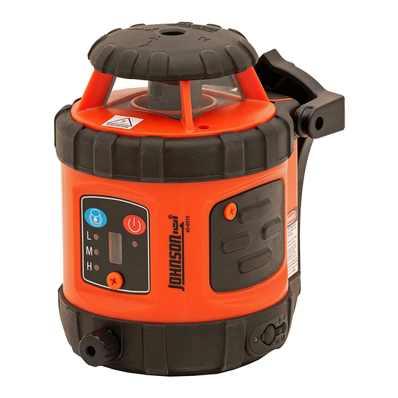
Self-Leveling Rotary Laser Level
Model Nos. 40-6515 and 40-6516
Instruction Manual
Congratulations on your choice of this Self-Leveling Rotary Laser
Level. We suggest you read this instruction manual thoroughly before
using the instrument. Save this instruction manual for future use.
This is a Class IIIa laser tool and is manufactured to comply
with CFR 21, parts 1040.10 and 1040.11 as well as international
safety rule IEC 285.
©2007 Johnson Level & Tool
1
Advertisement
Table of Contents

Related Manuals for AccuLine 40-6515


Summary of Contents for AccuLine 40-6515
- Page 1 ™ Self-Leveling Rotary Laser Level Model Nos. 40-6515 and 40-6516 Instruction Manual Congratulations on your choice of this Self-Leveling Rotary Laser Level. We suggest you read this instruction manual thoroughly before using the instrument. Save this instruction manual for future use.
-
Page 2: Table Of Contents
5. Location of Parts/Components 13. Product Registration 6. Operating Instructions 14. Accessories 7. Using the Product 1. Kit Contents For Model No. 40-6515 Description Qty. Self- Leveling Rotary Laser Level “AA” Alkaline Batteries Tinted Glasses Instruction Manual with Warranty Card Soft Sided Carrying Case For Model No. -
Page 3: Features And Functions
2. Features and Functions • Magnetic dampening compensation system. • If laser is out of its self-leveling range, rotation stops and alarm sounds. • Projects a horizontal laser plane. • Projects a vertical laser plane with 90° split beam reference. •... - Page 4 • Use only original AccuLine Pro ™ parts and accessories purchased from your AccuLine Pro authorized dealer. Use of non-AccuLine Pro parts and accessories will void warranty. WARNING! The tinted goggles are designed to enhance the visibility of the laser beam. They DO NOT offer protection to the eyes from direct exposure of the laser beam.
-
Page 5: Location/Content
4. Location/Content of Warning Labels ©2007 Johnson Level & Tool... -
Page 6: Location Of Parts/Components
5. Location of Part/Components 90° Split Beam Laser Output Window Battery Door Rotating Laser Output Widow Keypad Lock Knob – Compensator/ Transportation Vertical Vial Vertical Vial Adjustment Knob DC 6V Outlet (6V Adapter not included) 5/8” – 11 Screw Charging LED Thread ©2007 Johnson Level &... -
Page 7: Operating Instructions
6. Operating Instructions IMPORTANT: It is the responsibility of the user to verify the calibration of the instrument before each use. Alkaline Battery Installation Note: Always check to be sure that the on/off switch is in the off position before removing and replacing batteries. 1. - Page 8 Note: • For the first two charges of new rechargeable battery pack (not included), it is necessary to charge for 12-plus hours. • The instrument can still work even if it is being charged with adapter. • Do not charge alkaline batteries to avoid explosion. •...
-
Page 9: Using The Product
7. Using the Product Keypad Rotating speed Power Key switch key Low speed LED Middle speed LED Power LED High speed LED Before pressing the Power key, the compensator/transportation lock knob must be turned to the “On” position. Power Key: Press this key to power on/off the instrument. Power LED: Lighted LED mean power-on Extinguished LED means power-off Flashing LED means weak battery voltage... - Page 10 Out of Level Set the lock knob to the unlocked position. Power on. During the process of self-leveling, if the instrument is tilted to exceed its self-leveling range, it will stop rotating and will give a sound alarm. Application Methods Install Ni-MH battery pack (not included) or alkaline batteries into the instrument, or connect the instrument with 6V DC power supply (not included)
- Page 11 Note: 1. To use the laser in the self-leveling status, please set the lock knob to the “unlocked” position. 2. While the instrument is in the vertical status (manual mode), please set the lock knob to “lock” position. 3. Power on the instrument and select your desired speed by press- ing the keys on the keypad.
- Page 12 2. Components (a) Structure 1. Display window 2. Buzzer 3. Receiving window 4. Reference rabbet 5. Sound button 6. Coarse/Fine detection button 7. Power button 8. Threaded hole 9. Battery-box cap (b) Display 1. Power symbol 2. Low battery symbol 3.
- Page 13 3. Operation Guide (a) Installation of battery • Open the battery-box cap and connect the cords inside with the two polarities of the 9V battery. Note: Take the battery out if the instrument if not used for a long time. •...
- Page 14 (d) Detection 1. Coarse detection • Aim the receiving window at the rotating laser instrument. Loosen the clamp bolt and move the instrument up and downwards to receive the laser scanning signals transmitted by the rotating laser instrument. • When the instrument displays like Fig. (A), move the instrument slightly down- wards as indicated by the arrow.
- Page 15 e) Sound function • If the instrument is working in a circumstance that makes it difficult to use the display function, the sound function can be used instead. • Press the sound function button. The sound symbol is displayed which means it is ready for sound function. The instrument then conducts coarse/fine detection through sound (buzz) signals.
-
Page 16: Self-Check And Calibration
8. Self-Check and Calibration IMPORTANT: It is the responsibility of the user to verify the calibration of the instrument before each use. 25’ X-Direction Accuracy Self-Check 1. For clarity, we define the direction of handle as X-direction, and another direction as Y-direction 2. - Page 17 6. As shown, turn the instrument by 90° and place it on the platform, with the operating panel facing you. Perform Y-direction self-check with the same method as X-direction self-check, and mark point C and point D by turns. 7. If point C and point D are within 1/16” at 25’, the accuracy is within tolerance.
- Page 18 Accuracy Self-Check for Vertical Output Status 1. Follow the operations as above, and measure the distance H1 between the laser rotating plane and the platform surface. 2. Set the locking knob to locking position, and place the instrument horizontally. Wall 3.
-
Page 19: Technical Specifications
4. After adjustment operation, please install the bubble-adjustment- hole bolt back to its original position. Screw off the self-calibration-hole bolt Calibrate the bubble Note: If you fail to calibrate the accuracy according to the above steps, please contact Johnson Level & Tool for service. 9. -
Page 20: Application Demonstrations
10. Application Demonstrations Ceiling installation Wall or footing construction Squaring and leveling Baseboard installation Fence installation Cement floor installation Window installation Anti-static flooring installation ©2007 Johnson Level & Tool... -
Page 21: Care And Handling
Do not return this product to the store/retailer or place of purchase. Required repair must be done by an authorized AccuLine Pro™ service center or Johnson Level & Tool's limited warranty, if applicable, will be void and there will be NO WARRANTY. Contact... -
Page 22: Product Registration
Customer Service Department to obtain a Return Material Authorization (RMA) number for return to an authorized service center. Proof of purchase is required. NOTE: The user is responsible for the proper use and care of the product. It is the responsibility of the user to verify the calibration of the instrument before each use. -
Page 23: Accessories
14. Accessories AccuLine Pro™ accessories are available for purchase through authorized AccuLine Pro dealers. Use of non-AccuLine Pro accessories will void any applicable limited warranty and there will be NO WARRANTY. If you need any assistance in locating any accessories, please contact our Customer Service Department. -
Page 24: Johnson Level & Tool
©2007 Johnson Level & Tool...
Need help?
Do you have a question about the 40-6515 and is the answer not in the manual?
Questions and answers