Mira vigour Installation And User Manual
Thermostatic power shower
Hide thumbs
Also See for vigour:
- Installation and user manual (28 pages) ,
- Installation and user manual (32 pages)

Related Manuals for Mira vigour


Summary of Contents for Mira vigour
- Page 1 THERMOSTATIC POWER SHOWER Installation and User Guide These instructions are to be left with the user...
- Page 2 the nation’s favourite PLUMBING & HEATING SUPPLIES FREE SHIPPING SECURE PAYMENTS on all orders over £100 to mainland UK shop online with confidence FINANCE AVAILABLE PRICE MATCH spread the cost with low interest rates always get the best deals available we have H U G E R E D U C T I O N S...
-
Page 3: Table Of Contents
CONTENTS Introduction ..................... 3 Patents ....................3 Important Safety Information ..............3 Warning! ....................3 Caution! ....................4 Pack Contents ..................5 Dimensions ....................6 ..................7 Installation Requirements ..............8 Installation ....................9 General ....................9 Electrical ....................9 Plumbing .................... 10 Commissioning .................. -
Page 4: Introduction
INTRODUCTION The Mira Vigour Thermostatic Power Shower is an all-in-one power shower with mixer incorporates a wax capsule sensing unit. Designed to be surface mounted, the Thermostatic Power Shower comes complete Patents Patents GB: 2 340 210, 2 392 223, 2 392 224, 2 392 225... -
Page 5: Caution
10. Turn off the electrical and water supplies before removing the cover. The electricity must be turned off at the mains and, if applicable, the appropriate circuit fuse removed. 11. Mains connections are exposed when the cover is removed. 12. Moving parts are exposed when the cover is removed. 13. -
Page 6: Pack Contents
PACK CONTENTS 1 x Thermostatic Power Shower 4 x Case Inserts 1 x Flow Control Knob 1 x Temperature Indicator Trim 1 x Installation and User Guide 1 x Guarantee Registration Document 1 x Temperature Control Knob 3 x Rubber Wall Plugs 3 x Fixing Screws 1 x Push-Fit Release Tool 3 x Rubber Feet... -
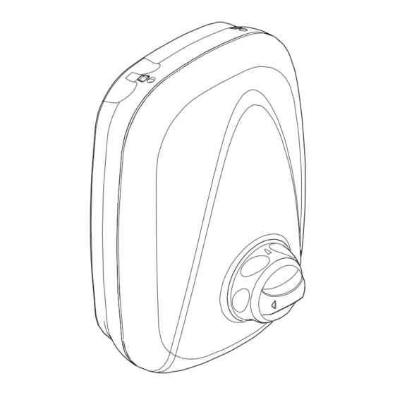
Page 7: Dimensions
DIMENSIONS All dimensions are nominal and in millimetres. - Page 8 Maximum maintained pressure - 50 kPa (0.5 bar). Maximum static pressure - 100 kPa (1 bar) or 10 m head of water. Duty Cycle - The Mira Vigour Thermostatic Power Shower pump is now continuously temperatures become too high due to abnormally high supply voltages.
-
Page 9: Installation Requirements
INSTALLATION REQUIREMENTS Gravity Fed system - The shower MUST be fed from a cold water cistern and hot water cylinder providing nominally equal pressure. 30° - 60° 10 m Maximum 80 mm Minimum... -
Page 10: Installation
INSTALLATION General Do not Do not Isolate electrical and water supplies before proceeding with the installation of the shower unit. The shower unit must be fed from a cold water storage cistern and hot water cylinder with equal pressures. The shower unit must not be connected to a mains cold water supply, unvented high pressure systems or multipoint/combination gas water heaters. -
Page 11: Plumbing
Plumbing A minimum being run dry. must be such that nominally equal inlet supply pressures are achieved and the effects on the shower performance of other draw-offs are minimised. the water supply. Avoid routing the high level hot feed pipe upward to the same level as the cold Do not may damage plastic components. - Page 12 Warning! installations have been completed. Decide on a suitable location for the shower unit avoiding buried cables and pipes. The unit should be positioned at a height convenient for The handset should spray away from Hose Retaining Ring the shower unit, either down the centre line of the bath or across the when the hose retaining ring is placed on the lowest position on the slide bar,...
- Page 13 Chamfer free from burrs, which will damage the inlet manifold seals. Chamfer the end of the pipe to assist the ‘O’ seal tearing. Warning! Do not result in injury. Caution! Thoroughly flush the incoming hot and cold water supply pipes to remove debris before Trim the thinned section of connecting the shower unit.
- Page 14 Temporarily locate the shower unit. Position the shower unit on the wall Note! Installers may wish to obtain for dry lined, stud partition or dry partition wall structures. the grey collars into the manifold to release the shower unit from the supply pipes.
- Page 15 12. Fit the three rubber feet into the Rubber Feet recesses in the rear of the case as shown. The feet will reduce the noise transmitted by the power shower through the wall. Warning! inside of the unit. Fit the half case in the following manner.
- Page 16 14. Locate the shower unit on the inlet supplies and push the inlet manifold felt. DO NOT FORCE! Note! PTFE tape or liquid jointing compound must not be used and is not required to assist connection. 15. The inlet manifold collet and ‘O’ seals will seal automatically.
- Page 17 the three cover securing screws. OFF Position OFF position. 21. Insert the temperature indicator trim and the inner temperature control 22. The power thermostatic shower will now require commissioning, refer to COMMISSIONING. Temperature Indicator Trim instruction manual supplied with the Inner Temperature Control Knob...
-
Page 18: Commissioning
COMMISSIONING The unit must not be run dry. Before proceeding any further with the installation the shower unit must be commissioned. of the shower unit. Hose Washer Caution! Do not over tighten. Hose Switch on the electrical supply. Maximum Flow Position Tu r n t h e o u t e r f l o w c o n t r o l Outer Flow Control anticlockwise... -
Page 19: Maximum Temperature Setting
Maximum Temperature Setting least 12 °C above the required temperature for correct operation of the thermostatic power shower. To reset the maximum outlet temperature follow the sequence below : Tu r n t h e o u t e r f l o w c o n t r o l anticlockwise Turn the inner temperature control anticlockwise to the maximum... - Page 20 Caution! When resistance is felt DO NOT USE FORCE to turn the spindle any further as this is the maximum shower temperature obtainable with the available hot water storage temperature. FORCE will DAMAGE the internal components. Turn the temperature spindle until the maximum water temperature required Temperature Spindle is obtained.
-
Page 21: Disabling The Temperature Override Button
Disabling the Temperature Override Button The temperature override button allows the user to override the preset maximum temperature. The temperature override button should be disabled if the power shower correct operation of the controls. Follow the instructions below to disable the temperature override button: clockwise to the off position and clockwise to full cold. -
Page 22: Operation
OPERATION with an adjustable maximum temperature as necessary to suit both site conditions and user’s comfort. until the desired flow of water is obtained. The flow of water will increase the further the control is turned anticlockwise. Outer Flow Control Knob Warmer Cooler Turn the inner temperature control... -
Page 23: Fault Diagnosis
FAULT DIAGNOSIS Fault Diagnosis - User Maintenance The appliance is fully performance tested after assembly. Providing it has been person responsible for installing your shower. Malfunction Cause Remedy Maximum Maximum temperature Reset maximum temperature, showering incorrectly set. refer to COMMISSIONING. temperature too hot. -
Page 24: Fault Diagnosis - Installer Maintenance
Providing the Thermostatic Power Shower has been correctly installed and is must be carried out by a competent person for whom the fault diagnosis table is provided. contacting the Mira Showers Customer Support Department, refer to the rear page. Malfunction... - Page 25 Malfunction Cause Remedy The maximum Hot water cylinder Adjust the cylinder shower temperature less than temperature. Note! It is temperature is too 12 °C above the showering recommended that the stored cold. temperature. water temperature does not exceed 65 °C. Maximum temperature Reset the maximum incorrectly set.
-
Page 26: Maintenance
MAINTENANCE Warning! There are no user serviceable components beneath the cover of the appliance. Only a competent tradesperson should remove the cover. Before removing the cover, the electricity supply must be turned off at the mains and if applicable, the appropriate circuit fuse removed. Mains electrical connections are exposed when the cover is removed. -
Page 27: Spare Parts
SPARE PARTS 453.01 Cartridge - Thermostatic 453.08 PCB Assembly - Power 453.14 Filter/Cap Assembly 453.28 Outlet Elbow Assembly 1532.332 Control Knob Assembly 1532.365 Cover... - Page 28 A,D,E 453.08 453.28 1532.365 147.67 B,E,F 453.01 453.14 1532.332...
-
Page 29: Customer Service
Our Service Force is available to provide a quality service Damage or defects if the product is taken apart, repaired or at a reasonable cost. You will have the assurance of a Mira modifi ed by any persons not authorised by Mira Showers trained engineer/agent, genuine Mira spare parts and a or our approved agents.
Need help?
Do you have a question about the vigour and is the answer not in the manual?
Questions and answers