Table of Contents
Advertisement
Safe Operation Practices • Set-Up • Operation • Maintenance • Service • Troubleshooting • Warranty
O
'
M
peratOr
s
anual
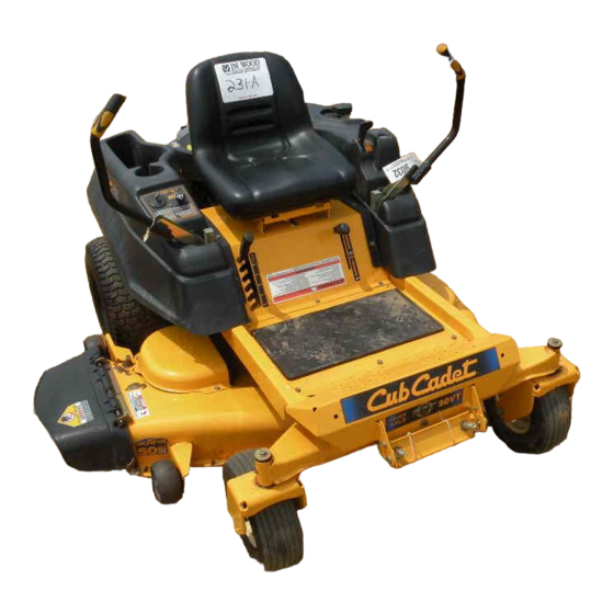
RZT Series Tractor — Model RZT50VT
WARNING
READ AND FOLLOW ALL SAFETY RULES AND INSTRUCTIONS IN THIS MANUAL
BEFORE ATTEMPTING TO OPERATE THIS MACHINE.
FAILURE TO COMPLY WITH THESE INSTRUCTIONS MAY RESULT IN PERSONAL INJURY.
CUB CADET LLC, P.O. BOX 361131 CLEVELAND, OHIO 44136-0019
Printed In USA
Form No. 769-05592
(December 7, 2009)
Advertisement
Table of Contents

Related Manuals for Cub Cadet RZT50VT


Summary of Contents for Cub Cadet RZT50VT
- Page 1 READ AND FOLLOW ALL SAFETY RULES AND INSTRUCTIONS IN THIS MANUAL BEFORE ATTEMPTING TO OPERATE THIS MACHINE. FAILURE TO COMPLY WITH THESE INSTRUCTIONS MAY RESULT IN PERSONAL INJURY. CUB CADET LLC, P.O. BOX 361131 CLEVELAND, OHIO 44136-0019 Printed In USA Form No. 769-05592...
-
Page 2: Table Of Contents
Choose from the options below: ◊ Visit us on the web at www.cubcadet.com ◊ Locate your nearest Cub Cadet Dealer at (877) 282-8684 ◊ Write us at Cub Cadet LLC • P.O. Box 361131 • Cleveland, OH • 44136-0019... -
Page 3: Safe Operation Practices
Important Safe Operation Practices WARNING! This symbol points out important safety instructions which, if not followed, could endanger the personal safety and/or property of yourself and others. Read and follow all instructions in this manual before attempting to operate this machine. Failure to comply with these instructions may result in personal injury. - Page 4 A missing or damaged discharge cover can cause blade If situations occur which are not covered in this manual, use contact or thrown object injuries. care and good judgment. Contact your customer service representative for assistance. Stop the blade(s) when crossing gravel drives, walks, or roads and while not cutting grass.
- Page 5 Children When practical, remove gas-powered equipment from the truck or trailer and refuel it on the ground. Tragic accidents can occur if the operator is not alert to the If this is not possible, then refuel such equipment on presence of children. Children are often attracted to the a trailer with a portable container, rather than from a machine and the mowing activity.
-
Page 6: Spark Arrestor
Do not modify engine Check the blade(s) and engine mounting bolts at frequent intervals for proper tightness. Also, visually inspect blade(s) To avoid serious injury or death, do not modify engine in any for damage (e.g., excessive wear, bent, cracked). Replace way. -
Page 7: Safety Symbols
Safety Symbols This page depicts and describes safety symbols that may appear on this product. Read, understand, and follow all instructions on the machine before attempting to assemble and operate. Symbol Description READ THE OPERATOR’S MANUAL(S) Read, understand, and follow all instructions in the manual(s) before attempting to assemble and operate WARNING—... - Page 8 2 — s ectiOn peratiOn ractices...
-
Page 9: Assembly & Set-Up
Assembly & Set-Up Contents of Crate • One Deck Wash Hose Coupler • One Lawn Tractor • One Oil Drain Tube • One RZT Tractor Operator’s • One Briggs & Stratton Engine Manual Operator’s Manual Tractor Preparation Remove the two shoulder bolts and lock nuts in the seat pan as shown in Fig. - Page 10 Connecting the Battery Cables Position Drive Control levers The drive control levers of the tractor are lowered for shipping CALIFORNIA PROPOSITION 65 WARNING purposes. The flange lock nuts, hex screws, and flat washers that Battery posts, terminals, and related accessories normally secure the control levers in their operating position contain lead and lead compounds, chemicals known are unfastened and installed in the slotted holes of the control...
- Page 11 Lower Deck Discharge Chute Deflector WARNING! Never operate the mower deck without the chute deflector installed and in the down position. Check the mower deck for a shipping brace (with tag) that may be holding the chute deflector upward for shipment. If a brace is present, it must be removed before operating the tractor.
-
Page 12: Controls & Features
Controls and Features Deck Lift Deck Height Handle Index Parking Brake Throttle/Choke PTO Switch Control LH Drive RH Drive Ignition Switch Hour Meter/ Control Lever Control Lever Indicator Panel Seat Adjustment Lever Cup Holder Fuel Tank Cap Storage Tray Figure 4-1 NOTE: References to LEFT, RIGHT, FRONT, and REAR indicate that RH and LH Drive Control Levers position on the tractor when facing forward while seated in the... -
Page 13: Ignition Switch
Ignition Switch Do not attempt to remove the cap from the tractor. Push the cap downward on the fuel tank fill neck and turn The ignition switch is located on the RH console approximately 1⁄4 turn clockwise to tighten Always re-install the to the right of the operator’s seat. - Page 14 Pull the lever up out of the “J” slot and to the right; then operation, check the battery and charging system for possible lower completely to disengage the parking brake. causes and/or contact your Cub Cadet dealer. NOTE: If the LH and RH drive control levers are not fully Oil Pressure Indicator opened out in the neutral position when engaging the This warning lamp indicates low engine oil pressure.
-
Page 15: Operation
Contact your authorized • Avoid operation on traction surfaces that are unstable; use Cub Cadet Dealer. extreme caution if the surface is slippery. • The safety interlock system prevents the engine from •... -
Page 16: Starting The Engine
• The safety interlock system will shut off the engine if the Turn the ignition key clockwise to the “START” position operator leaves the seat with the PTO engaged, regardless and release it as soon as the engine starts; however, do not of whether the parking brake is engaged. -
Page 17: Driving The Tractor
Stopping the Engine Move the RH and LH drive control levers inward in the neutral position. Refer to Figure 5-2. Place the PTO switch in the “OFF” position. Move the RH and LH drive control levers fully outward in the neutral position. Engage the parking brake. - Page 18 Driving the Tractor Forward To turn to the left, move the left drive control lever rearward of the right lever. See Fig. 5-4. WARNING! Keep all movement of the drive control levers slow and smooth. Abrupt movement of the control levers can affect the stability of the tractor and could cause the tractor to flip over, which may result in serious injury or death to the operator.
- Page 19 Driving the Tractor In Reverse Turning While Driving Rearward WARNING! To turn the tractor while driving rearward, move the control Always look behind and down on both levers as necessary so that one lever is forward of the other. The sides of the tractor before backing up.
- Page 20 Executing a Zero Turn Stopping the Tractor WARNING! Move both drive control levers to the neutral position to When executing a zero turn, the tractor stop the motion of the tractor. MUST BE STOPPED. Executing a zero turn while the tractor is moving can significantly reduce your Push the PTO switch downward to the disengaged control of the tractor and will cause severe turf...
- Page 21 If a safety circuit is not working as designed, free of debris, sticks, stones, wire or other objects contact you Cub Cadet dealer to have the tractor inspected. DO that can be thrown by the rotating blades. NOT operate the tractor if any safety circuit is not functioning properly.
-
Page 22: Maintenance & Adjustment
Maintenance & Adjustments Maintenance Schedule Before Every Every Every Every Prior Each use 10 Hours 25 Hours 50 Hours 100 Hours to Storing Check Engine Intake Screen/Cover Clean Hood/Dash Louvers Check Engine Oil Level Check Air Filter for Dirty, Loose or Damaged Parts Clean and Re-oil Air Filter’s Foam Precleaner Replace Air Filter Element Change Engine Oil and Replace Oil Filter... - Page 23 Using a pressure lubricating gun, lubricate the front castor season. Refer to the Briggs & Stratton Owner’s Manual for correct wheel axles and the front pivot axle with Cub Cadet 251H plug type and gap specifications. EP grease after every 10 hours of service.
- Page 24 • Periodically lubricate all other pivot points with a quality Using the Transmission Bypass Rods lubricating oil. If for any reason the tractor will not drive or you wish to move the Using the Deck Wash System tractor, the two hydrostatic transmissions are equipped with a bypass rod that will allow you to manually move the tractor short WARNING! When using the deck wash system,...
- Page 25 Battery Storage Emptying the fuel system: • Prior to putting the tractor in storage, monitor When storing the tractor for extended periods, disconnect fuel consumption with the goal of running the negative battery cable. It is not necessary to remove the fuel tank empty.
-
Page 26: Pivot Bracket
Adjustments While supporting the control lever to keep it from falling, remove the hex insert flange lock nut and shoulder screw WARNING! Shut the engine off, remove the from the bottom of the control lever and pivot bracket. Refer to Fig. 6-5. ignition key and engage the parking brake before making adjustments. - Page 27 Front to Back Leveling. Leveling the Mower Deck The front of the deck should be approximately 1⁄4” lower When correctly adjusted the mower deck should be level side to than the rear of the deck. Adjust if necessary as follows: side, and the front of the deck should be approximately 1⁄4”...
- Page 28 Adjusting the Gauge Wheels WARNING! Keep hands and feet away from the discharge opening of the cutting deck. NOTE: The deck gauge wheels are an anti-scalp feature of the deck and are not designed to support the weight of the cutting deck.
-
Page 29: Service
This If you have a recurring problem with blown fuses, have the will prevent sparking or possible injury from an tractor’s electrical system checked by your Cub Cadet Service electrical short caused by contacting the tractor Dealer... -
Page 30: Deck Removal
PTO pulley on the bottom of Cub Cadet Service Dealer. the engine. Sitting behind the tractor facing forward, reach beneath Deck Removal the tractor to grasp the belt at the front of the PTO pulley. -
Page 31: Deck Installation
Deck Installation Lower the deck to the ground using the deck lift handle. Locate the LH and RH deck support pins on each side of the To install the mower deck, proceed as follows: deck. Pull the deck support pins outward and lock in the While holding the deck front hanger rod upward, carefully disengaged position to release the deck from the tractor’s slide the deck underneath the right side of the tractor. - Page 32 Mower Blade Care Rolling the Belt onto the PTO Pulley. Using the deck lift handle, raise the deck to the position WARNING! Before performing any maintenance, that provides the most horizontal run of the belt between place the PTO switch in the “OFF” position, engage the deck idler pulleys and the PTO pulley on the bottom of the parking brake lever, turn the ignition key to the the engine.
-
Page 33: Transmission Drive Belt
Tractor Creeping When reinstalling the blades, be sure they are installed so that the wind wings are pointing upward toward the top of Creeping is the slight forward or backward movement of the the deck. tractor when the engine is running at high idle and the drive Tighten the blade nuts to 70-90 ft. - Page 34 Tractor High Speed Tracking If the tractor tracks to one side with both drive control levers fully forward, adjust the control levers as follows: Check for proper and balanced air pressure in both front and rear tires. Refill tires if necessary. Perform the first three steps in the previous sub-section, Tractor Creeping, to verify that the tractor is not creeping.
-
Page 35: Troubleshooting
Troubleshooting Problem Cause Remedy Engine fails to start PTO/Blade Engage knob engaged. Place knob in disengaged (OFF) position. Parking brake not engaged. Engage parking brake. Drive control levers not fully outward in Move drive control levers fully outward in neutral position. neutral position. - Page 36 Problem Cause Remedy Engine overheats Engine oil level low. Fill crankcase with proper amount and weight of oil. Air flow restricted. Clean grass clippings and debris from around the engine’s cooling fins and blower housing. Engine hesitates at high Spark plug(s) gap too close. Remove spark plug(s) and reset the gap.
-
Page 37: Replacement Parts
Replacement Parts Component Part Number and Description 759-3336 Spark Plug (RC12YC) BS-792105 Air Filter Element BS-792303 Foam Pre-cleaner BS-696854 Oil Filter BS-691035 Fuel Filter 954-04044A Drive Belt (Mowing Deck) 954-04043A Drive Belt (Transmissions) 942-04053C 2-in-1 Deck Blade 918-04125A Deck Spindle Phone (800) 965-4CUB to order replacement parts or a complete Parts Manual (have your full model number and serial number ready). - Page 38 Component Part Number and Description 734-04155 Deck Wheel 925-1707D Battery 751-10703 Fuel Tank Cap 746-04539 Throttle Control Cable 925-1745 Ignition Key 631-04070A Discharge Chute Assembly 634-04128 Wheel Assembly 634-04321A Caster Wheel Assembly Phone (800) 965-4CUB to order replacement parts or a complete Parts Manual (have your full model number and serial number ready).
-
Page 39: Attachments & Accessories
Attachments & Accessories The following attachments and accessories are compatible with your Cub Cadet RZT tractor. See your Cub Cadet dealer or the retailer from which you purchased your tractor for information regarding price and availability. Part Number Part 19A70004100... - Page 40 Notes...
- Page 41 11 — n ectiOn Otes...
-
Page 42: Warranties
FEDERAL and/or CALIFORNIA EMISSION CONTROL WARRANTY STATEMENT YOUR WARRANTY RIGHTS AND OBLIGATIONS MTD Consumer Group Inc, the United States Environmental Protection Agency (EPA), and, for those products certified for sale in the state of California, the California Air Resources Board (CARB) are pleased to explain the emission (evaporative and/or exhaust) control system (ECS) warranty on your outdoor 2006 and later small off-road spark-ignited engine and equipment (outdoor equipment engine) In California, new outdoor equipment engines must be designed, built and equipped to meet the State’s stringent anti-smog standards (in other states, 1997 and later model year equipment must be designed, built, and equipped to meet the U.S. - Page 43 WARRANTED PARTS: The repair or replacement of any warranted part otherwise eligible for warranty coverage may be excluded from such warranty coverage if MTD Consumer Group Inc demonstrates that the outdoor equipment engine has been abused, neglected, or improperly maintained, and that such abuse, neglect, or improper mainte- nance was the direct cause of the need for repair or replacement of the part.
- Page 44 Without limiting the foregoing, this limited warranty does not provide coverage in the following cases: The limited warranty set forth below is given by Cub Cadet LLC with respect to new merchandise purchased or leased and used in the a. Routine maintenance items such as lubricants, filters, blade...