Table of Contents
Advertisement
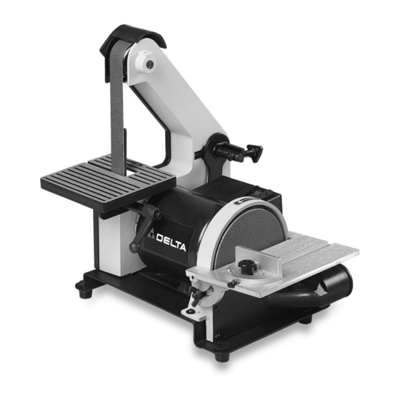
1" Belt / 5" Disc
Sander
(Model 31-080)
PART NO. 901607 (0112)
Copyright © 2001 Delta Machinery
To learn more about DELTA MACHINERY
ESPAÑOL: PÁGINA 13
visit our website at: www.deltamachinery.com.
For Parts, Service, Warranty or other Assistance,
1-800-223-7278 (
1-800-463-3582).
please call
In Canada call
Advertisement
Table of Contents

Related Manuals for Delta 31-080


Summary of Contents for Delta 31-080
- Page 1 1" Belt / 5" Disc Sander (Model 31-080) PART NO. 901607 (0112) Copyright © 2001 Delta Machinery To learn more about DELTA MACHINERY ESPAÑOL: PÁGINA 13 visit our website at: www.deltamachinery.com. For Parts, Service, Warranty or other Assistance, 1-800-223-7278 ( 1-800-463-3582).
-
Page 2: General Safety Rules
If you have any questions relative to a particular application, DO NOT use the machine until you have first contacted Delta to determine if it can or should be performed on the product. -
Page 3: Additional Safety Rules For Belt / Disc Sanders
8. MAKE SURE the sanding belt or disc is not torn or loose. 27. THE USE of attachments and accessories not recommended by Delta may result in the risk of injuries. 9. HOLD the work firmly when sanding. 28 IF ANY PART of your sander is missing, damaged, 10. -
Page 4: Power Connections
POWER CONNECTIONS A separate electrical circuit should be used for your machines. This circuit should not be less than #12 wire and should be protected with a 20 Amp time lag fuse. If an extension cord is used, use only 3-wire extension cords which have 3- prong grounding type plugs and matching receptacle which will accept the machine’s plug. -
Page 5: Extension Cords
OPERATING INSTRUCTIONS FOREWORD The Delta Model 31-080 Belt/Disc Sander is a handy machine for sanding wood, metal, plastic, or ceramic workpieces. This machine incorporates a 1" belt sander and a 5" disc sander, and uses an induction-type ball bearing motor for long-lasting performance. -
Page 6: Assembly
ASSEMBLY ATTACHING BELT SANDER TABLE 1. DISCONNECT MACHINE FROM POWER SOURCE. 2. Locate the 1-3/16" long screw (A) Fig. 2, M8.4 flat washer (B), and table locking handle assembly (C), (D), (E) and (F). NOTE: The table locking assembly (C, D, E, and F) is shipped assembled. -
Page 7: Attaching Abrasive To Sanding Disc
Fig. 8 Fig. 7 ATTACHING ABRASIVE TO SANDING DISC 1. DISCONNECT MACHINE FROM POWER SOURCE. 2. Remove one-half of the abrasive backing (A) Fig. 7, to expose the adhesive. 3. Attach the lower section of the abrasive to the sanding disc (B), making sure that the abrasive edges fit the sanding disc edges exactly. -
Page 8: Operating Controls And Adjustments
OPERATING CONTROLS AND ADJUSTMENTS STARTING AND STOPPING SANDER The switch (A) Fig. 15 is located on the top of the switch box. To start the sander, move the switch to the “ON” position. To stop the sander, move the switch to the “OFF”... -
Page 9: Disc Table Adjustments
4. The table can be tilted to the front (Fig. 19), by loosening table locking handle (C), tilting the table to the desired angle and tightening the table locking handle (C). 5. The table can be adjusted in or out by loosening the table locking handle and moving the table in or out. -
Page 10: Changing Sanding Disc
CHANGING ABRASIVE BELT 1. DISCONNECT MACHINE FROM POWER SOURCE. 2. Remove lock knob (A) Fig. 23, and remove side cover (B). 3. Depress tracking knob (C) Fig. 24, to release belt tension and remove belt (D) from the three wheels (E), as shown. -
Page 11: Accessories
(B) is for the disc unit. angle and tightening lock knob (B). ACCESSORIES A complete line of accessories is available from your Delta Supplier, Porter-Cable • Delta Factory Service Centers, www.deltamachinery.com and Delta Authorized Service Stations. Please visit our Web Site for a catalog or for the name of your nearest supplier. -
Page 12: Parts, Service Or Warranty Assistance
Two Year Limited Warranty Delta will repair or replace, at its expense and at its option, any Delta machine, machine part, or machine accessory which in normal use has proven to be defective in workmanship or material, provided that the customer returns the product prepaid to a Delta factory service center or authorized service station with proof of purchase of the product within two years and provides Delta with reasonable opportunity to verify the alleged defect by inspection.
Need help?
Do you have a question about the 31-080 and is the answer not in the manual?
Questions and answers
What is proper length of belt on Delta 31-080 1” sander