Advertisement
Table of Contents
- 1 Safety Guidelines - Definitions
- 2 General Safety Rules
- 3 Additional Safety Rules
- 4 Motor Specifications
- 5 Power Connections
- 6 Grounding Instructions
- 7 Extension Cords
- 8 Functional Description
- 9 Unpacking and Cleaning
- 10 Dust Port
- 11 Sanding Spindle
- 12 Operating Controls and Adjustments
- 13 Belt Tracking
- 14 Maintenance
- 15 Parts, Service or Warranty Assistance
- Download this manual
Advertisement
Table of Contents

Related Manuals for Delta 31-396


Summary of Contents for Delta 31-396
- Page 1 Oscillating Edge Sander (Model 31-396) PART NO. 909448 - 03-18-03 Copyright © 2003 Delta Machinery To learn more about DELTA MACHINERY visit our website at: www.deltamachinery.com. For Parts, Service, Warranty or other Assistance, 1-800-223-7278 ( 1-800-463-3582). please call In Canada call...
-
Page 2: Safety Guidelines - Definitions
SAFETY GUIDELINES - DEFINITIONS This manual contains information that is important for you to know and understand. This information relates to protect- ing YOUR SAFETY and PREVENTING EQUIPMENT PROBLEMS. To help you recognize this information, we use the symbols to the right. Please read the manual and pay attention to these sections. Indicates an imminently hazardous situation which, if not avoided, will result in death or serious injury. -
Page 3: Additional Safety Rules
12. USE THE RIGHT MACHINE. Don’t force a machine or an attachment to do a job for which it was not designed. Damage to the machine and/or injury may result. 13. USE RECOMMENDED ACCESSORIES. The use of accessories and attachments not recommended by Delta may cause damage to the machine or injury to the user. -
Page 4: Motor Specifications
A separate electrical circuit should be used for your machines. This circuit should not be less than #12 wire and should be protected with a 20 Amp time lag fuse. If an extension cord is used, use only 3-wire extension cords which have 3- prong grounding type plugs and matching receptacle which will accept the machine’s plug. -
Page 5: Extension Cords
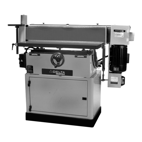
FOREWORD Delta Model 31-396 is an Oscillating Edge Sander. The model 31-396 is powered by a 3 H.P., 220 volt single phase motor. The oscillating edge belt can be positioned anywhere from 0 degrees to the table to 90 degrees to the table. The model 31-396 also comes with a spindle sander attachment kit that is used for sanding curved surfaces. - Page 6 3. Lift up on hook (H) Fig. 3, and remove the shelfs (J) and (K). 4. Remove the four screws that attach the sander base to the shipping skid. Note: Two of the screws are shown at (L) Fig. 4.
- Page 7 OSCILLATING EDGE SANDER PARTS 1. Fence 2. Table Assembly 3. Cover 4. Miter Gage 5. Back Stop 6. Dust Port 7. 4" Hose Connector 8. Spindle 9. 1½" Dia. Drum 10. 2" Dia. Drum 11. 3” Dia. Drum 12. 3" Table Insert 13.
- Page 8 FOR YOUR OWN SAFETY, DO NOT CONNECT THE MACHINE TO THE POWER SOURCE UNTIL THE MACHINE IS COMPLETELY ASSEMBLED AND YOU READ AND UNDERSTAND THE ENTIRE INSTRUCTION MANUAL. BELT 1. Remove knobs (C) and (D) Fig. 6. 2. Open latch (B) Fig. 6, and carefully lower cover (F). 3.
- Page 9 BACK STOP NOTE: THE BOTTOM OF THE BACK STOP (C) FIG. 13 SHOULD BE SET SLIGHTLY ABOVE THE BELT SANDER TABLE. 1. Place a 5/16" flat washer on each 5/16-18 x 1" hex head screw. Thread screws into table two complete turns.
- Page 10 COVER 1. Align the hinges (A) Fig. 14, on the cover, with the hinges (B) on the belt guard. 2. Insert hinge pins (C) and (D) Fig. 15, through the hinges on the cover and belt guard. 3. Tap the hinge pins in with hammer and rod (supplied).
-
Page 11: Dust Port
DUST PORT 1. Align the four holes on the dust port (A) Fig. 17, with the four tapped holes (B) on the side of the belt sander. 2. Place a 17/64" flat washer on a 1/4-20x3/8" round head screw, insert the screw through the hole in the dust port, and thread the screw into the tapped hole on the side of the belt sander. - Page 12 2. Move belt guard (B) down as shown in Fig. 20. 3. Remove the three screws (C) and drum plate (D) Fig. 4. Align the three holes in spindle (E) Fig. 21, with the three tapped holes (F) in the drum. 5.
- Page 13 7. Thread the ratchet handle (J) Fig. 24, into the tapped hole (K) and tighten securely. NOTE: ratchet handle (J) is spring loaded and can be repositioned by pulling out on the lever and repositioning it on the serrated nut located underneath the lever.
- Page 14 12. Assemble appropriate table insert onto the table using the three screws that were removed in STEP 10. FENCE If sanding with the belt in the horizontal position, the use of the fence is recommended. 1. Place the fence (A) on the table as shown in Fig. 29. 2.
-
Page 15: Operating Controls And Adjustments
OPERATING CONTROLS AND ADJUSTMENTS STARTING AND STOPING OSCILLATING EDGE SANDER The power switch is located on the left side of the machine. To turn the machine “ON” press the green start button (A) Fig. 31. To stop the machine, push the red stop button (B). - Page 16 2. Pull out on the table height wheel handle (C) Fig. 35. 3. Rotate table height wheel clockwise to raise the table and counter clockwise to lower the table. 4. When the table height is at the desired position tighten ratchet handles (A) and (B) Fig. 34. TABLE DISTANCE TO BELT DISCONNECT MACHINE FROM POWER SOURCE.
-
Page 17: Belt Tracking
ANGLE OF BELT SANDER DISCONNECT MACHINE FROM POWER SOURCE. 1. The belt sander can be tilted from 0 degrees to the table up to 90 degrees to the table. 2. Move the table to the front of the machine. Grasp the tilting handle (C) Fig. - Page 18 3. The table can also be positioned on the oscillating belt by removing the table insert, and sliding the table down around the oscillating belt. Replace the table insert with the 4" table insert (D) Fig. 44, when using the sander table on the oscillating belt. FENCE DISCONNECT MACHINE FROM POWER SOURCE.
- Page 19 T-Slot groove in the table. This allows the miter gage to be pulled off the front edge of the table without falling. The Oscillating Edge Sander can be used to perform many different sanding operations. The following examples will show some of the applications that this machine can be used for.
- Page 20 4. Fig. 52 shows sanding at 90 degrees to the table with the miter gage. 5. Fig. 53 shows the spindle sander being used in the vertical position. It is advisable to raise or lower the table periodically to prevent spot wear and improve drum life.
-
Page 21: Maintenance
500 hours, check oil level. DISCONNECT MACHINE FROM POWER SOURCE. 1. Make sure that the belt sander is in the horizontal position as shown in Fig. 55. 2. Remove the two screws (A) Fig. 56, on top of the gear box cover (G) Fig. 55. - Page 22 REMOVING THE DRUM DISCONNECT MACHINE FROM POWER SOURCE. 1. Open the belt sander guards and remove the sanding belt. 2. Remove nut (A) and washer from the shaft (J) Fig. 59. 3. Insert the two 1/4-20x1-3/4" socket head screws through holes (C) and (D) Fig. 60, on the retraction plate (E).
-
Page 23: Parts, Service Or Warranty Assistance
A complete line of accessories is available from your Delta Supplier, Porter-Cable • Delta Factory Service Centers, and Delta Authorized Service Stations. Please visit our Web Site for the name of your nearest supplier. Since accessories other than those offered by Delta have not been tested with this product, use of such accessories could be hazardous. - Page 24 PORTER-CABLE (CENTROS DE SERVICIO DE PORTER-CABLE Parts and Repair Service for Porter-Cable (Obtenga Refaccion de Partes o Servicio para su Herramienta en los Siguientes Centros de Porter-Cable ARIZONA ILLINOIS Tempe 85282 (Phoenix) Addison 60101 (Chicago) 2400 West Southern Avenue 400 South Rohlwing Rd. Suite 105 Phone: (630) 424-8805 Phone: (602) 437-1200...
Need help?
Do you have a question about the 31-396 and is the answer not in the manual?
Questions and answers