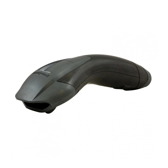
Honeywell Voyager 1200g User Manual
Single-line laser bar code scanner
Hide thumbs
Also See for Voyager 1200g:
- Quick start manual ,
- User manual (238 pages) ,
- User manual (230 pages)
Table of Contents
Advertisement
Advertisement
Table of Contents
Troubleshooting

Related Manuals for Honeywell Voyager 1200g


Summary of Contents for Honeywell Voyager 1200g
- Page 1 Voyager™ 1200g/1202g Single-Line Laser Bar Code Scanner User’s Guide ™...
- Page 2 Disclaimer Honeywell International Inc. (“HII”) reserves the right to make changes in speci- fications and other information contained in this document without prior notice, and the reader should in all cases consult HII to determine whether any such changes have been made. The information in this publication does not repre- sent a commitment on the part of HII.
- Page 3 The user may find the fol- lowing booklet helpful: “Something About Interference.” This is available at FCC local regional offices. Honeywell is not responsible for any radio or television interference caused by unauthorized modifications of this equip- ment or the substitution or attachment of connecting cables and equipment other than those specified by Honeywell.
- Page 4 Nijverheidsweg 9-13 5627 BT Eindhoven The Netherlands Honeywell International Inc. shall not be liable for use of our product with equipment (i.e., power supplies, personal computers, etc.) that is not CE marked and does not comply with the Low Voltage Directive.
- Page 5 This product has required the extraction and use of natural resources for its production. It may contain hazardous substances that could impact health and the environment, if not properly disposed. In order to avoid the dissemination of those substances in our environment and to diminish the pressure on the natural resources, we encourage you to use the appropriate take-back systems for product disposal.
- Page 6 South Korea This product meets Korean agency approval. Taiwan If the following label is attached to your product, the product meets Taiwan agency approval: BSMI Standard: CNS13438, CNS 14336 依據標準 : CNS13438, CNS14336 International LED Safety Statement LEDs have been tested and classified as “EXEMPT RISK GROUP” to the standard: IEC 62471:2006.
-
Page 7: Solids And Water Protection
Patents For patent information, please refer to www.honeywellaidc.com/patents. Solids and Water Protection The Voyager 1200g has a rating of IP42, immunity of foreign particles and drip- ping water. - Page 8 Caution: Any changes or modifications made to this equipment not expressly approved by Honeywell may void the FCC authorization to operate this equipment. Use only shielded data cables with this system. This unit has been tested with cables less than 3 meters.
- Page 9 5627 BT Eindhoven The Netherlands Honeywell shall not be liable for use of our product with equipment (i.e., power supplies, personal computers, etc.) that is not CE marked and does not comply with the Low Voltage Directive. This equipment is intended for...
- Page 10 If you need more information on the collection, reuse, and recycling sys- tems, contact your local or regional waste administration. You may also contact your supplier for more information on the environ- mental performances of this product. Australia/NZ C-Tick Statement Conforms to AS/NZS 3548 EMC requirements.
- Page 11 BSMI Standard: CNS13438, CNS14336 (Voyager 1202 only) 依據標準 : CNS13438, CNS14336 NCC standard: Low power frequency electric machineries technical standard: LP0002 International LED Safety Statement LEDs have been tested and classified as “EXEMPT RISK GROUP” to the standard: IEC 62471:2006. Radio Technology Class II CB Scheme...
- Page 12 Embedded Laser Wavelength 645- 660 nm Divergence < 1.5 mrad, per IEC 60825-1 worst case Max power output < 10 mw Caution - use of controls or adjustments or performance of procedures other than those specified herein may result in hazardous radiation expo- sure.
- Page 13 Voyager 1200g Safety Label Locations Laser Output Internal Laser Cautions Compliance Markings information, Part Number, and Serial Number information Compliance Markings information...
- Page 14 Voyager 1202g Safety Label Locations Laser Output Internal Laser Cautions Laser Safety Information Compliance Markings information, Part Number, and Serial Number information Compliance Markings information...
- Page 15 CCB00-010BT Safety Label Locations Item Number, Compliance Serial Markings Number, and information Compliance Markings information...
-
Page 17: Table Of Contents
Table of Contents Chapter 1 - Getting Started About This Manual ............1-1 Unpacking Your Device..........1-1 Connecting the Device ..........1-2 Connecting with USB ..........1-2 Connecting with Keyboard Wedge ......1-3 Connecting with RS232 Serial Port ....... 1-5 Connecting with RS485......... - Page 18 ® Verifone Ruby Terminal Default Settings ....2-9 ® Gilbarco Terminal Default Settings ......2-9 Honeywell Bioptic Aux Port Configuration ....2-10 © Datalogic™ Magellan Bioptic Aux Port Configuration ..........2-10 NCR Bioptic Aux Port Configuration ......2-10 Wincor Nixdorf Terminal Default Settings....2-11 Wincor Nixdorf Beetle™ Terminal Default Settings ...2-12 Keyboard Country Layout ..........2-13...
- Page 19 Scanner-Bioptic Packet Mode ......2-28 ACK/NAK............. 2-28 Communication Timeout ........2-28 Chapter 3 - Cordless System Operation How the Charge and Communications Base Works ... 3-1 Linking the Scanner to a Base ........3-1 Communication Between the Cordless System and the Host.............. 3-2 RF (Radio Frequency) Module Operation ....
- Page 20 Charge Only Mode..........3-10 Linked Modes ............3-11 Unlinking the Scanner..........3-11 Override Locked Scanner ..........3-12 Out-of-Range Alarm...........3-12 Alarm Sound Type ..........3-12 Alarm Duration ............. 3-12 Scanner Power Time-Out Timer ........3-13 Batch Mode..............3-13 Batch Mode Beep ..........3-14 Batch Mode Quantity ........... 3-14 Delete Last Code ..........
- Page 21 Beeper Pitch – Good Read ........4-3 Beeper - Transmit Order ........4-3 Beeper Pitch – Error..........4-3 Beeper Duration – Good Read......4-4 Number of Beeps – Good Read ......4-4 Number of Beeps – Error ........4-4 LED Indicators............. 4-6 LED Settings ............
- Page 22 Partial Sequence ..........4-21 Require Output Sequence ........4-21 No Read..............4-22 Chapter 5 - Data Editing Prefix/Suffix Overview..........5-1 To Add a Prefix or Suffix: ........5-1 To Clear One or All Prefixes or Suffixes ....5-2 To Add a Carriage Return Suffix to All Symbologies..........
- Page 23 Chapter 7 - Symbologies All Symbologies............7-1 Message Length Description........7-2 Codabar ..............7-3 Codabar Concatenation ........7-4 Code 39............... 7-7 Code 32 Pharmaceutical (PARAF)......7-9 Full ASCII .............. 7-9 Interleaved 2 of 5 ............7-11 NEC 2 of 5..............7-13 Code 93..............
- Page 24 EAN-13 Beginning with 978 Addenda Required ......... 7-50 EAN-13 Beginning with 979 Addenda Required ......... 7-51 ISBN Translate ............ 7-53 ISSN Translate ............ 7-54 EAN/JAN-8 ..............7-55 MSI ................7-58 Plessey Code.............7-60 GS1 DataBar Omnidirectional ........7-62 GS1 DataBar Limited..........7-63 GS1 DataBar Expanded ..........7-64 Trioptic Code .............7-65 GS1 Emulation............7-65 Postal Codes .............7-66...
- Page 25 Read Time-Out............ 10-4 Resetting the Standard Product Defaults ....10-4 Menu Commands ............10-6 Chapter 11 - Product Specifications Voyager 1200g Product Specifications ..... 11-1 Voyager 1202g Product Specifications ..... 11-3 CCB00-010BT Product Specifications ...... 11-4 CCB00-010BT Mounting ........... 11-6 Standard Cable Pinouts ..........
- Page 26 ASCII Conversion Chart (Code Page 1252) ....A-4 Code Page Mapping of Printed Barcodes ....A-6...
-
Page 27: Chapter 1 - Getting Started
Voyager 1200g/1202g linear scanner. Product specifications, dimensions, war- ranty, and customer support information are also included. Honeywell bar code scanners are factory programmed for the most common terminal and communications settings. If you need to change these settings, programming is accomplished by scanning the bar codes in this guide. -
Page 28: Connecting The Device
Connecting the Device Connecting with USB A scanner or a base can be connected to the USB port of a computer. Connect the appropriate interface cable to the scanner first, then to the computer. Charge and Communications Base USB Connection: Make sure the cables are secured in the wireways in the bottom of the base and that the base sits flat on a horizontal surface. -
Page 29: Connecting With Keyboard Wedge
Verify the scanner or base operation by scanning a bar code from the Sample Symbols in the back of this manual. The unit defaults to a USB PC Keyboard. Refer to page 2-5 for other USB terminal settings. For additional USB programming and technical information, refer to “USB Application Note,”... - Page 30 Charge and Communications Base Keyboard Wedge Connection: Make sure the cables are secured in the wireways in the bottom of the base and that the base sits flat on a horizontal surface. Turn the terminal/computer power back on. The scanner beeps. Verify the scanner or base operation by scanning a bar code from the Sample Symbols in the back of this manual.
-
Page 31: Connecting With Rs232 Serial Port
Connecting with RS232 Serial Port Turn off power to the terminal/computer. Connect the appropriate interface cable to the scanner. Note: For the scanner or base to work properly, you must have the correct cable for your type of terminal/computer. only if power supply is included... -
Page 32: Connecting With Rs485
Make sure the cables are secured in the wireways in the bottom of the base and that the base sits flat on a horizontal surface. Plug the serial connector into the serial port on your computer. Tighten the two screws to secure the connector to the port. Once the scanner or base has been fully connected, power up the computer. -
Page 33: Reading Techniques
15° to 18° to prevent unwanted reflection. Menu Bar Code Security Settings Honeywell scanners are programmed by scanning menu bar codes or by send- ing serial commands to the scanner. If you want to restrict the ability to scan menu codes, you can use the Menu Bar Code Security settings. -
Page 34: Setting Custom Defaults
Setting Custom Defaults You have the ability to create a set of menu commands as your own, custom defaults. To do so, scan the Set Custom Defaults bar code below before each menu command or sequence you want saved. If your command requires scan- ning numeric codes from the back cover, then a Save code, that entire... -
Page 35: Resetting The Custom Defaults
Resetting the Custom Defaults If you want the custom default settings restored to your scanner, scan the Acti- vate Custom Defaults bar code below. This resets the scanner to the custom default settings. If there are no custom defaults, it will reset the scanner to the factory default settings. - Page 36 1 - 10...
-
Page 37: Chapter 2 - Programming The Interface
Programming the Interface Introduction This chapter describes how to program your system for the desired interface. Programming the Interface - Plug and Play Plug and Play bar codes provide instant scanner set up for commonly used interfaces. Note: After you scan one of the codes, power cycle the host terminal to have the interface in effect. -
Page 38: Rs485
RS232 Interface RS485 Scan one of the following “Plug and Play” codes to program the scanner for an IBM POS terminal interface. Note: After scanning one of these codes, you must power cycle the cash register. IBM Port 5B Interface IBM Port 9B HHBCR-1 Interface IBM Port 17 Interface... -
Page 39: Opos Mode
OPOS Mode The following bar code configures your scanner for OPOS (OLE for Retail Point of Sale) by modifying the following OPOS-related settings: Option Setting Interface RS232 Baud Rate 38400 RS232 Flow Control, No Timeout Handshaking XON/XOFF Off ACK/NAK Off Data Bits, Stop 8 Data, 1 Stop, Parity None Bits, and Parity... -
Page 40: Usb Ibm Surepos
USB IBM SurePos Scan one of the following “Plug and Play” codes to program the scanner for an IBM SurePos (USB handheld scanner) or IBM SurePos (USB tabletop scanner) interface. Note: After scanning one of these codes, you must power cycle the cash register. -
Page 41: Usb Pc Or Macintosh Keyboard
USB PC or Macintosh Keyboard Scan one of the following codes to program the scanner for USB PC Key- board or USB Macintosh Keyboard. Scanning these codes also adds a CR and LF. USB Keyboard (Mac) USB Japanese Keyboard (PC) USB HID Scan the following code to program the scanner for USB HID bar code scanners. -
Page 42: Usb Serial Commands
Scan one of the following codes to program the scanner to emulate a regu- lar RS232-based COM Port. If you are using a Microsoft® Windows® PC, you will need to download a driver from the Honeywell website (www.honeywellaidc.com). The driver will use the next available COM Port number. -
Page 43: Ack/Nak Mode
ACK/NAK Mode ACK/NAK Mode On * ACK/NAK Mode Off Communication Timeout This allows you to set the length (in milliseconds) for a timeout for the host ACK/NAK response. Scan the bar code below, then set the timeout (from 0-65535 milliseconds) by scanning digits from the Programming Chart, then scanning Save. -
Page 44: Nak Retries
Communication Timeout Beeper This selection programs the scanner to issue an error beep when a communication timeout has occurred. The error beep sound is pro- (page 4-4). Default = On. grammed using Number of Beeps – Error * On NAK Retries This selection limits the number of NAK retries that can occur in ACK/NAK mode. -
Page 45: Verifone ® Ruby Terminal Default Settings
® Verifone Ruby Terminal Default Settings Scan the following Plug and Play code to program the scanner for a Verifone Ruby terminal. This bar code sets the baud rate to 1200 bps and the data for- mat to 8 data bits, Mark parity, 1 stop bit and RTS/CTS no timeout. It also adds a line feed (LF) suffix and programs the following prefixes for each symbology: Symbology Prefix... -
Page 46: Honeywell Bioptic Aux Port Configuration
Honeywell Bioptic Aux Port Configuration Scan the following Plug and Play code to program the scanner for a Honeywell bioptic scanner auxiliary port configuration. This bar code sets the baud rate to 38400 bps and the data format to 8 data bits, no parity, 1 stop bit. Character RTS/CTS with timeout and 232 ACK/NAK are also enabled. -
Page 47: Wincor Nixdorf Terminal Default Settings
NCR Bioptic Settings Note: If you are having unexpected results with this programming code, scan Activate Defaults bar code on page 1-9 first, then scan the programming code above. Wincor Nixdorf Terminal Default Settings Scan the following Plug and Play code to program the scanner for a Wincor Nix- dorf terminal. -
Page 48: Wincor Nixdorf Beetle™ Terminal Default Settings
Wincor Nixdorf Beetle™ Terminal Default Settings Scan the following Plug and Play code to program the scanner for a Wincor Nix- dorf Beetle terminal. The following prefixes are programmed for each symbol- ogy: Symbology Prefix Symbology Prefix Code 128 EAN-13 Code 93 GS1-128 Codabar... -
Page 49: Keyboard Country Layout
Keyboard Country Layout Scan the appropriate country code below to program the keyboard layout for your country or language. As a general rule, the following characters are sup- ported, but need special care for countries other than the United States: @ | $ # { } [ ] = / ‘... -
Page 50: Keyboard Wedge Modifiers
Keyboard Country (continued) Russia Slovenia Spain Switzerland (German) Thailand Turkey Q United Kingdom Vietnam Keyboard Wedge Modifiers ALT Mode If your bar code contains special characters from the extended ASCII chart for example, an e with an accent grave (è), you will use ALT Mode. (See Extended ASCII Characters on page A-5.) Note: Scan the ALT mode bar code after scanning the appropriate... -
Page 51: Keyboard Style
If your keystrokes require using the ALT key and 3 characters, scan the 3 Characters bar code. If your keystrokes require the ALT key and 4 charac- ters, scan the 4 Characters bar code. The data is then output with the spe- cial character(s). -
Page 52: Keyboard Conversion
Autocaps via NumLock bar code should be scanned in countries (e.g., Germany, France) where the Caps Lock key cannot be used to toggle Caps Lock. The NumLock option works similarly to the regular Autocaps, but uses the NumLock key to retrieve the current state of the Caps Lock. Autocaps via NumLock Emulate External Keyboard should be scanned if you do not have an external keyboard (IBM AT or equivalent). -
Page 53: Inter-Scan Code Delay
Control + ASCII Mode On: The scanner sends key combinations for ASCII control characters for values 00-1F (refer to the ASCII chart for Non- Printable Characters, page A-4). Windows is the preferred mode. All key- board country codes are supported. DOS mode is a legacy mode, and it does not support all keyboard country codes. -
Page 54: F0> Break Character
between scan codes. Set the length (in milliseconds) for a delay by scan- ning the bar code below, then setting the delay (from 1-30) by scanning dig- Chart, then scanning Save. Default = 0 (800 µs) . its from the Programming Inter-Scan Code Delay <F0>... -
Page 55: Rs232 Modifiers
RS232 Modifiers RS232 Baud Rate Baud Rate sends the data from the scanner to the terminal at the specified rate. The host terminal must be set for the same baud rate as the scanner. Default = 9600. 1200 2400 4800 * 9600 19200 38400... -
Page 56: Rs232 Word Length: Data Bits, Stop Bits, And Parity
RS232 Word Length: Data Bits, Stop Bits, and Parity Data Bits sets the word length at 7 or 8 bits of data per character. If an application requires only ASCII Hex characters 0 through 7F decimal (text, digits, and punctuation), select 7 data bits. For applications that require use of the full ASCII set, select 8 data bits per character. -
Page 57: Rs232 Handshaking
7 Data, 2 Stop, Parity Space 8 Data, 1 Stop, Parity Space 7 Data, 1 Stop, Parity Mark 7 Data, 2 Stop, Parity Mark 8 Data, 1 Stop Parity Mark RS232 Handshaking RS232 Handshaking allows control of data transmission from the scanner using software commands from the host device. -
Page 58: Rs232 Timeout
Character-Based Flow Control with Timeout: The scanner asserts RTS when it has a character to send and waits for a delay (see RS232 Timeout on page 2-22) for CTS to be asserted by the host. If the delay time expires and CTS is not asserted, the device transmit buffer is cleared and scanning may resume. -
Page 59: Xon/Xoff
XON/XOFF Standard ASCII control characters can be used to tell the scanner to start sending data (XON/XOFF On) or to stop sending data (XON/XOFF Off). When the host sends the XOFF character (DC3, hex 13) to the scanner, data transmission stops. To resume transmission, the host sends the XON character (DC1, hex 11). -
Page 60: Nak Retries
Timeout Retries This setting limits the number of Communication Timeout retries. If the Timeout Retries is set to 0, the transmission is terminated after the initial Communication Timeout. Scan the bar code below, then set the number of retries (from 0-255) by scanning digits from the Programming Chart, then scanning Save. -
Page 61: Support Bel/Can In Ack/Nak
Support BEL/CAN in ACK/NAK This protocol responds to <BEL> and <CAN> commands when in ACK/ NAK mode. The scanner sounds an error tone when a <BEL> command is sent from the host. <CAN> terminates the transmission. Default = BEL/ CAN Off . BEL/CAN On * BEL/CAN Off RS232 Defaults... -
Page 62: Block Check Character
Block Check Character When this selection is set to Transmit, the NCR Block Check Character (BCC) is expected with incoming messages and transmitted with outgoing messages. Default = Transmit. * Transmit Don’t Transmit NCR Prefix This selection allows you to program an NCR-specific prefix. Refer to the ASCII Conversion Chart (Code Page 1252) on page A-4 to find the hex equivalent for the characters you want for the NCR prefix (typically, 02 for... -
Page 63: Ncr Prefix/Suffix
When set to Off, no sound is emitted for an NOF. Default = Off. * Off Scanner to Bioptic Communication The following settings are used to set up communication between Honeywell scanners and bioptic scanners. Note: The scanner’s baud rate must be set to 38400 and the RS232 Timeout must be set to 3000 in order to communicate with a bioptic scanner. -
Page 64: Scanner-Bioptic Packet Mode
Scanner-Bioptic Packet Mode Packet Mode On must be scanned to set the scanner’s format so it is com- patible with a bioptic scanner. Default = Packet Mode Off. * Packet Mode Off Packet Mode On ACK/NAK After transmitting data, the scanner waits for an ACK character (hex 06) or a NAK character (hex 15) response from the host. -
Page 65: Chapter 3 - Cordless System Operation
Cordless System Operation Note: This chapter applies only to cordless scanning systems. It does not apply to corded scanners. How the Charge and Communications Base Works A cordless charge and communications base provides the link between the cordless scanner and the host system. The base contains an interface assem- bly and an RF communication module. -
Page 66: Communication Between The Cordless System And The Host
To determine if your cordless system is set up correctly, scan one of the sample bar codes in the back of this manual. If the scanner provides a single good read beep and the green LED lights, the scanner has successfully linked to the base. If you receive an error tone and the red LED lights, the scanner has not linked to the base. -
Page 67: System Conditions
tant to noisy RF environments. The Bluetooth Class 2 power level provides a communication range of 33 feet (10m) between the scanner and base, depend- ing on the environment. System Conditions The components of the cordless system interact in specific ways as you associ- ate the scanner with its base, as you move a scanner out of range, or bring a scanner back in range. -
Page 68: About The Battery
About the Battery There is a danger of explosion if the batteries are incorrectly replaced. Replace the batteries with only the same or equivalent type recom- mended by the manufacturer. Dispose of used batteries according to the recycle program for batteries as directed by the governing agency for the country where the batteries are to be discarded. -
Page 69: Battery Recommendations
The model Voyager 1202g is designed for use with Honeywell battery pack model 100000495 (Li-ion 3.7Vdc, 7.4 watt hour). Place the scanner in the base that is connected to an appropriate power supply. Use only a Listed Limited Power Source (LPS) or Class 2 type power supply with output rated 5 to 5.2Vdc, 1A. -
Page 70: Proper Disposal Of The Battery
Caution: Danger of explosion if batteries are incorrectly replaced. Dispose of used batteries according to the recycle program for batteries as directed by the governing agency for the country where the batteries are to be discarded. Proper Disposal of the Battery When the battery has reached the end of its useful life, the battery should be disposed of by a qualified recycler or hazardous materials handler. -
Page 71: Base Led Sequences And Meaning
LED Indication Beeper Indication Cause Green Flash 2 beeps Successful menu change Red, blinking Razz or error tone Unsuccessful menu change Base LED Sequences and Meaning The base contains a red LED that indicate the status of the unit and verifies its communication with the host system. -
Page 72: Reset Scanner
Reset Scanner Scanning this bar code reboots the scanner and causes it to relink with the base. Reset Scanner Scanning While in Base Cradle If you want to be able to scan bar codes while the scanner is in the base, scan the following Scanning in Cradle On bar code. -
Page 73: Paging Pitch
red LED on the base will remain lit to indicate that Paging Mode is off. (This light will go out when the button is pressed, then back on when it’s released.) Default = Paging Mode On. * Paging Mode On Paging Mode Off Pitch Paging... -
Page 74: Base Address
Base Address Scan the following bar code to determine the address of the base you are using. Base Address Scanner Modes The Voyager is capable of working with Bluetooth devices other than the CCB00-010BT charge base. Charge Only Mode There may be times when you want to charge your scanner, but not link to the base. -
Page 75: Linked Modes
Linked Modes Locked Link Mode and Open Link Mode are the link modes that accommo- date different applications. Scan the appropriate bar codes included in the Open Link and Locked Link Mode explanations that follow to switch from one mode to another. Default = Open Link Mode . Locked Link Mode - Single Scanner If you link a scanner to a base using the Locked Link Mode, other scanners are blocked from being linked if they are inadvertently placed... -
Page 76: Override Locked Scanner
Override Locked Scanner If you need to replace a broken or lost scanner that is linked to a base, scan the following Override Locked Scanner bar code with a new scanner and place that scanner in the base. The locked link will be overridden, the broken or lost scanner’s link with the base will be removed, and the new scanner will be linked. -
Page 77: Scanner Power Time-Out Timer
Scanner Power Time-Out Timer Note: Scanner Power Time-out Timer only applies to cordless systems. It does not apply to corded scanners. When there is no activity within a specified time period, the scanner enters low power mode. Scan the appropriate scanner power time-out bar code to change the time-out duration (in seconds). -
Page 78: Batch Mode Beep
Automatic Batch Mode stores bar code data when the scanner is out of range of the base. The data is automatically transmitted to the base once the scanner is back in range. When the scanner’s buffer space is full, any bar codes scanned generate an error tone. - Page 79 three times. Using Batch Mode Quantity On and the Quantity Codes (page 3-16), you could output your data as “00003, XYZ” instead. Default = Batch Mode Quantity Off. * Batch Mode Quantity Off Batch Mode Quantity On Entering Quantities Quantity Codes (page 3-16) allow you to enter a quantity for the last item scanned, up to 9999 (default = 1).
- Page 80 Quantity Codes 3 - 16...
-
Page 81: Delete Last Code
Delete Last Code If you want to delete the last bar code scanned when in Batch Mode, scan Delete Last Code. Delete Last Code Record Counter If you wish to add a record counter to each bar code scanned in Batch Mode, scan Record Counter On. -
Page 82: Batch Mode Output Order
Batch Mode Output Order When batch data is transmitted, select whether you want that data sent as FIFO (first-in first-out), or LIFO (last-in first-out). Default = Batch Mode FIFO. * Batch Mode FIFO Batch Mode LIFO Clear All Codes After Transmission If you want to clear the scanner’s buffer of all data accumulated in Batch Mode after the data has been transmitted to the host system, scan Clear All Codes After Transmission. -
Page 83: Transmit Records Automatically
Transmit Records Automatically If you are operating in Inventory Batch Mode (see Inventory Batch Mode page 3-14), you can transmit all stored data to the host system when the scanner is placed in the base. If you don’t want the records transmitted when the scanner is placed in the base, scan the Don’t Transmit Records Automatically bar code. -
Page 84: Batch Mode Transmit Delay
Batch Mode Transmit Delay Sometimes when accumulated scans are sent to the host system, the transmission of those scans is too fast for the application to process. To program a transmit delay between accumulated scans, scan one of the fol- lowing delays. - Page 85 To rename scanners with sequential, numeric names, scan the following bar codes. Scan the Reset code after each name change and wait for the scanner to relink to the base. 0001 0002 0003 0004 0005 0006 0007 Reset You may also scan the following Scanner Name bar code and scan up to 30 numbers and/or letters for the scanner name.
-
Page 86: Using The Scanner With Bluetooth Devices
Using the Scanner with Bluetooth Devices The scanner can be used either with the CCB00-010BT charge base or with other Bluetooth devices. Those devices include personal computers and lap- tops. Scanning the following Non-Base BT Connection bar code allows the scanner to be used with other Bluetooth devices (e.g., PC/laptop). -
Page 87: Auto Reconnect Mode
Auto Reconnect Mode Auto Reconnect controls whether or not the scanner automatically begins the relink process when a loss of connection is detected. When the Auto Reconnect On bar code is scanned, the scanner begins the relink process immediately, without user intervention. Default = Auto Reconnect On. * Auto Reconnect On Auto Reconnect Off The following table shows the results of the Auto Reconnect On and Off... -
Page 88: Maximum Link Attempts
Maximum Link Attempts The Maximum Link Attempts setting controls the number of times the scan- ner tries to form a connection with a base. During the connection setup process, the scanner transmits in order to search for and connect to a base. -
Page 89: Reset Scanner And Base
Maximum Link Attempts set to 15 Other values at default settings When the scanner goes out of range, 15 attempts are made to link to the base unit. Each attempt consists of approximately 5 seconds of active time followed by 3 seconds of idle time. After 15 cycles (8*15 =120), or about 2 minutes, the scanner stops trying to connect to the base, but retains any bar codes that may have been saved in batch mode. - Page 90 3 - 26...
-
Page 91: Chapter 4 - Input/Output Settings
Input/Output Settings Power Up Beeper The scanner can be programmed to beep when it’s powered up. Scan the Off bar code(s) if you don’t want a power up beep. Default = Power Up Beeper On - Scanner. Power Up Beeper Off - Scanner * Power Up Beeper On - Scanner... -
Page 92: Good Read And Error Indicators
Good Read and Error Indicators Beeper – Good Read The beeper may be programmed On or Off in response to a good read. Turning this option off, only turns off the beeper response to a good read indication. All error and menu beeps are still audible. Default = Beeper - Good Read On. -
Page 93: Beeper Pitch - Good Read
Beeper Pitch – Good Read The beeper pitch codes modify the pitch (frequency) of the beep the scan- ner emits on a good read. Default = Medium. Low (1600 Hz) * Medium (2350 Hz) High (4200 Hz) Beeper - Transmit Order The beeper transmit order determines when the good read beep occurs. -
Page 94: Beeper Duration - Good Read
Beeper Duration – Good Read The beeper duration codes modify the length of the beep the scanner emits on a good read. Default = Normal. * Normal Beep Short Beep Short Beep Number of Beeps – Good Read The number of beeps of a good read can be programmed from 1 - 9. The same number of beeps will be applied to the beeper and LED in response to a good read. - Page 95 To change the number of error beeps, scan the following bar code and then scan a digit (1-9) bar code and the Save bar code on the Programming inside the back cover of this manual. Default = 1. Chart Number of Error Beeps/LED Flashes 4 - 5...
-
Page 96: Led Indicators
LED Indicators The green and red LEDs can be programmed to be On or Off and at different brightness levels to indicate various scanner states. Use the following bar codes to program the LED indicators. LED Settings Default = Red LED On with Laser, Green LED On with Good Scan. Red LED Off Green LED Off Red LED On with Good Scan... - Page 97 Red LED On with CTS Green LED On with CTS Red LED On when Battery is Low Green LED On when Battery is Low 4 - 7...
-
Page 98: Led Brightness
LED Brightness Default = Red High, Green High. Red Off Green Off Red Low Green Low Red Medium Green Medium * Red High * Green High In-Stand and Out-Of-Stand Settings The following settings program the scanner’s behavior when it is either in the stand, or out of the stand (hand-held). -
Page 99: In-Stand And Out-Of-Stand Defaults
In-Stand and Out-of-Stand Defaults If you want the In-Stand or Out-of-Stand default settings restored to your scanner, scan the appropriate Defaults bar code below. They reset the scanner to the custom default settings (see Setting Custom Defaults page 1-8). If there are no custom defaults, it will reset the scanner to the factory default settings. -
Page 100: Manual Activation Mode
Manual Activation Mode In Manual Activation Mode, you must press the button to scan a bar code. The scanner scans until a bar code is read, or until the button is released. Default = Manual Activation Mode On In-Stand, Manual Activation On Out- of-Stand. -
Page 101: Manual Activation Laser Timeout - Button Settings
Manual Activation Laser Timeout - Button Settings You can set a timeout for the length of time the laser remains on and attempting to decode bar codes when the button is held down, and after it is released. Set the length (in milliseconds) for a timeout by scanning one of the following bar codes, then setting the timeout (from 1-65535 millisec- onds) by scanning digits from the Programming... -
Page 102: Codegate
® CodeGate When CodeGate is On, the button is used to allow decoded data to be transmitted to the host system. The scanner remains on, scanning and decoding bar codes, but the bar code data is not transmitted until the but- ton is pressed. -
Page 103: End Object Detection After Good Read
End Object Detection After Good Read After a bar code is successfully detected and read from the scanner, the laser can be programmed either to remain on and scanning, or to turn off. When End Object Detection After Good Read is enabled, the laser turns off and stops scanning after a good read. -
Page 104: Object Detection Distance
Object Detection Distance When the scanner is in the stand and you are using Object Detection Mode, you can set the distance range for detecting objects. Short sets the scanner to detect objects approximately 5 inches (12.7cm) away from the nose. -
Page 105: End Character Activation After Good Read
trigger scanning. Scan the following bar code, then use the Programming Chart to read the alphanumeric combination that represents that ASCII character. Scan Save to finish. Activation Character End Character Activation After Good Read After a bar code is successfully detected and read from the scanner, the laser can be programmed either to remain on and scanning, or to turn off. -
Page 106: Character Deactivation Mode
Character Deactivation Mode If you have sent a character from the host to trigger the scanner to begin scan- ning, you can also send a deactivation character to stop scanning. Scan the fol- lowing On bar code to use character deactivation, then use Deactivation Character (following) to select the character you will send from the host to termi- nate scanning. -
Page 107: Reread Delay
Reread Delay This sets the time period before the scanner can read the same bar code a sec- ond time. Setting a reread delay protects against accidental rereads of the same bar code. Longer delays are effective in minimizing accidental rereads. Use shorter delays in applications where repetitive bar code scanning is required. -
Page 108: Output Sequence Editor
Output Sequence Editor This programming selection allows you to program the scanner to output data (when scanning more than one symbol) in whatever order your appli- cation requires, regardless of the order in which the bar codes are scanned. Reading the Default Sequence symbol programs the scanner to the following Universal values. - Page 109 Output Sequence Example In this example, you are scanning Code 93, Code 128, and Code 39 bar codes, but you want the scanner to output Code 39 1st, Code 128 2nd, and Code 93 3rd, as shown below. Note: Code 93 must be enabled to use this example. A - Code 39 B - Code 128 C - Code 93...
-
Page 110: Output Sequence Editor
SEQBLKsequence editor start command code identifier for Code 39 0012 A - Code 39 sample length (11) plus CR suffix (1) = 12 start character match for Code 39, 41h = “A” termination string for first code code identifier for Code 128 0013 B - Code 128 sample length (12) plus CR suffix (1) = 13 start character match for Code 128, 42h = “B”... -
Page 111: Sequence Match Beeper
Sequence Match Beeper By default, the scanner beeps when a sequence match is found. If you want the scanner to remain silent, scan the following Sequence Match Beeper Off bar code. Default = Sequence Match Beeper On. Sequence Match Beeper Off * Sequence Match Beeper On Partial Sequence If an output sequence operation is terminated before all your output... -
Page 112: No Read
When the output sequence is Off , the bar code data is output to the host as the scanner decodes it. Default = Off. Required On/Not Required *Off No Read With No Read turned On, the scanner notifies you if a code cannot be read. If using an EZConfig-Scanning Tool Scan Data Window (see page 9-2), an “NR”... -
Page 113: Chapter 5 - Data Editing
Data Editing Prefix/Suffix Overview When a bar code is scanned, additional information is sent to the host computer along with the bar code data. This group of bar code data and additional, user-defined data is called a “message string.” The selections in this section are used to build the user-defined data into the message string. -
Page 114: To Clear One Or All Prefixes Or Suffixes
symbology to which you want to apply the prefix or suffix. For example, for Code 128, Code ID is “j” and Hex ID is “6A”. Step 3. Scan the 2 hex digits from the Programming Chart inside the back cover of this manual or scan 9, 9 for all symbologies. Step 4. -
Page 115: To Add A Carriage Return Suffix To All Symbologies
Step 1. Scan the Clear One Prefix or Clear One Suffix symbol. Step 2. Determine the 2 digit Hex value from the Symbology Chart (included in the Symbology Chart, beginning on page A-1) for the symbology from which you want to clear the prefix or suffix. Step 3. -
Page 116: Suffix Selections
Suffix Selections Add Suffix Clear One Suffix Clear All Suffixes Transmit Alternate Extended ASCII Characters You may need to emulate special keyboard functions, such as up or down arrows, Alt/Make or Alt/Break commands, that are not supported in the Extended ASCII Character table. Refer to Alternate Extended ASCII Characters (page 5-5) for a range of keyboard function keys and corresponding... - Page 117 Alternate Extended ASCII Characters DEC HEX Keyboard Function DEC HEX Keyboard Function ↑ 128 80 152 98 up arrow ↓ 129 81 153 99 down arrow → 130 82 154 9A right arrow ← 131 83 155 9B left arrow 132 84 Insert 156 9C Numeric Keypad +...
-
Page 118: Function Code Transmit
Function Code Transmit When this selection is enabled and function codes are contained within the scanned data, the scanner transmits the function code to the terminal. Charts of these function codes are provided in Supported Interface Keys starting on page 8-2. -
Page 119: Intercharacter, Interfunction, And Intermessage Delays
Intercharacter, Interfunction, and Intermessage Delays Some terminals drop information (characters) if data comes through too quickly. Intercharacter, interfunction, and intermessage delays slow the transmission of data, increasing data integrity. Intercharacter Delay An intercharacter delay of up to 5000 milliseconds (in 5ms increments) may be placed between the transmission of each character of scanned data. -
Page 120: Interfunction Delay
Next, scan the Character to Trigger Delay bar code, then the 2-digit hex value for the ASCII character that will trigger the delay ASCII Conversion Chart (Code Page 1252) on page A-4. Delay Length Character to Trigger Delay To remove this delay, scan the Delay Length bar code, and set the number of delays to 0. -
Page 121: Intermessage Delay
Intermessage Delay An intermessage delay of up to 5000 milliseconds (in 5ms increments) may be placed between each scan transmission. Scan the following Inter- message Delay bar code, then scan the number of 5ms delays, and the Save bar code using the Programming Chart inside the back cover of this manual. - Page 122 5 - 10...
-
Page 123: Chapter 6 - Data Formatting
Data Formatting Data Format Editor Introduction You may use the Data Format Editor to change the scanner’s output. For exam- ple, you can use the Data Format Editor to insert characters at certain points in bar code data as it is scanned. The selections in the following pages are used only if you wish to alter the output. - Page 124 you are programming. (See Primary/Alternate Data Formats on page 6-10 for further information.) Step 3. Terminal Type Refer to Terminal ID Table (page 6-4) and locate the Terminal ID number for your PC. Scan three numeric bar codes on the Programming Chart to program the scanner for your terminal ID (you must enter 3 digits).
-
Page 125: Other Programming Selections
Other Programming Selections Clear One Data Format This deletes one data format for one symbology. If you are clearing the primary format, scan 0 from the Programming Chart inside the back cover of this manual. If you are clearing an alternate format, scan 1, 2, or 3, depending on the format you are clearing. -
Page 126: Terminal Id Table
Terminal ID Table Terminal Terminal Model(s) PC/AT and compatibles PS2 Keyboard USB SurePOS Handheld Scanner USB SurePOS Tabletop Scanner RS232 True RS485 Serial PC Keyboard Mac Keyboard Japanese Keyboard (PC) HID POS Data Format Editor Commands Send Commands Send all characters F1 Include in the output message all of the characters from the input message, starting from current cursor position, followed by an insert character. -
Page 127: Move Commands
A-4 for decimal, hex and character codes. Insert symbology name B3 Insert the name of the bar code’s symbology in the output message, without moving the cursor. Only symbologies with a Honeywell ID are included (see Symbology Chart on page A-1). -
Page 128: Search Commands
Move the cursor to the beginning F7 Move the cursor to the first character in the input message. Syntax = Move the cursor to the end EA Move the cursor to the last character in the input message. Syntax = Search Commands Search forward for a character F8 Search the input message forward for “xx”... -
Page 129: Miscellaneous Commands
Search forward for a non-matching character E6 Search the input message forward for the first non-“xx” character from the current cursor position, leaving the cursor pointing to the non-“xx” character. Syntax = E6xx where xx stands for the search character’s hex value for its ASCII code. -
Page 130: Data Formatter
Compare characters FE Compare the character in the current cursor position to the character “xx.” If characters are equal, move the cursor forward one position. Syntax = FExx where xx stands for the comparison character’s hex value for its ASCII code. Refer to the ASCII Conversion Chart (Code Page 1252) on page A-4... -
Page 131: Data Format Non-Match Error Tone
Data Formatter On, Not Required, Drop Prefix/Suffix Scanned data is modified according to your data format. If a data format is found for a particular symbol, those prefixes and suffixes are not transmitted. Data Format Required, Keep Prefix/Suffix Scanned data is modified according to your data format, and prefixes and suffixes are transmitted. -
Page 132: Primary/Alternate Data Formats
will sound. If you wish to hear the error tone when a non-matching bar code is found, scan the Data Format Non-Match Error Tone On bar code. Default = Data Format Non-Match Error Tone On . * Data Format Non-Match Error Tone On Data Format Non-Match Error Tone Off... - Page 133 For example, you may have set your device to the data format you saved as Data Format 3. You can switch to Data Format 1 for a single button press by scanning the following Single Scan-Data Format 1 bar code. The next bar code that is scanned uses Data Format 1, then reverts back to Data Format 3.
- Page 134 6 - 12...
-
Page 135: All Symbologies
Symbologies This programming section contains the following menu selections. Refer to Chapter 10 for settings and defaults. • All Symbologies • GS1-128 • Airline Code 5 - see Straight 2 of 5 • Interleaved 2 of 5 IATA (two-bar start/stop) •... -
Page 136: Message Length Description
Message Length Description You are able to set the valid reading length of some of the bar code symbolo- gies. If the data length of the scanned bar code doesn’t match the valid read- ing length, the scanner will issue an error tone. You may wish to set the same value for minimum and maximum length to force the scanner to read fixed length bar code data. -
Page 137: Codabar
Codabar <Default All Codabar Settings> Codabar On/Off * On Codabar Start/Stop Characters Start/Stop characters identify the leading and trailing ends of the bar code. You may either transmit, or not transmit Start/Stop characters. Default = Don’t Transmit . Transmit * Don’t Transmit Codabar Check Character Codabar check characters are created using different “modulos.”... -
Page 138: Codabar Concatenation
When Check Character is set to Validate, but Don’t Transmit , the unit will only read Codabar bar codes printed with a check character, but will not transmit the check character with the scanned data. * No Check Character Validate Modulo 16, but Don’t Transmit Validate Modulo 16 and Transmit... -
Page 139: Concatenation Timeout
Select Require to prevent the scanner from decoding a single “D” Codabar symbol without its companion. This selection has no effect on Codabar symbols without Stop/Start D characters. * Off Require Concatenation Timeout When searching for bar codes during concatenation, you may wish to set a delay used to find the next bar code. -
Page 140: Codabar Message Length
Codabar Message Length Scan the following bar codes to change the message length. Refer to Message Length Description (page 7-2) for additional information. Mini- mum and Maximum lengths = 1-80. Minimum Default = 3, Maximum Default = 80. Minimum Message Length Maximum Message Length 7 - 6... -
Page 141: Code 39
Code 39 < Default All Code 39 Settings > Code 39 On/Off * On Code 39 Start/Stop Characters Start/Stop characters identify the leading and trailing ends of the bar code. You may either transmit, or not transmit Start/Stop characters. Default = Don’t Transmit. -
Page 142: Code 39 Message Length
When Check Character is set to Validate and Transmit, the scanner only reads Code 39 bar codes printed with a check character, and will transmit this character at the end of the scanned data. Default = No Check Charac- ter. * No Check Character Validate, but Don’t Transmit Validate and Transmit... -
Page 143: Code 32 Pharmaceutical (Paraf)
Code 32 Pharmaceutical (PARAF) Code 32 Pharmaceutical is a form of the Code 39 symbology used by Ital- ian pharmacies. This symbology is also known as PARAF. * Off Full ASCII If Full ASCII Code 39 decoding is enabled, certain character pairs within the bar code symbol will be interpreted as a single character. - Page 144 Character pairs /M and /N decode as a minus sign and period respectively. Character pairs /P through /Y decode as 0 through 9. Full ASCII On * Full ASCII Off 7 - 10...
-
Page 145: Interleaved 2 Of 5
Interleaved 2 of 5 < Default All Interleaved 2 of 5 Settings > Interleaved 2 of 5 On/Off * On Follett Formatting * Off NULL Characters Interleaved 2 of 5 requires an even number of characters. When an odd number of characters is present, it is due to NULL characters embedded in the bar code. -
Page 146: Check Digit
Check Digit No Check Digit indicates that the scanner reads and transmits bar code data with or without a check digit. When Check Digit is set to Validate, but Don’t Transmit, the unit only reads Interleaved 2 of 5 bar codes printed with a check digit, but will not transmit the check digit with the scanned data. -
Page 147: Interleaved 2 Of 5 Message Length
Interleaved 2 of 5 Message Length Scan the bar codes below to change the message length. Refer to Message Length Description (page 7-2) for additional information. Mini- mum and Maximum lengths = 1-80. Minimum Default = 6, Maximum Default = 80. Minimum Message Length Maximum Message Length NEC 2 of 5... - Page 148 When Check Digit is set to Validate and Transmit, the scanner only reads NEC 2 of 5 bar codes printed with a check digit, and will transmit this digit at the end of the scanned data. Default = No Check Digit. * No Check Digit Validate, but Don’t Transmit Validate and Transmit...
-
Page 149: Code 93
Code 93 < Default All Code 93 Settings > Code 93 On/Off * On Code 93 Redundancy If you are encountering errors when reading Code 93 bar codes, you may want to adjust the redundancy count. Redundancy adjusts the number of times a bar code is decoded before transmission, which may reduce the number of errors. -
Page 150: Straight 2 Of 5 Industrial (Three-Bar Start/Stop)
Code 93 Message Length Scan the bar codes below to change the message length. Refer to Message Length Description (page 7-2) for additional information. Mini- mum and Maximum lengths = 1-80. Minimum Default = 3, Maximum Default = 80. Minimum Message Length Maximum Message Length Straight 2 of 5 Industrial (three-bar start/stop) <Default All Straight 2 of 5 Industrial Settings>... -
Page 151: Straight 2 Of 5 Industrial Message Length
scan a redundancy count between 0 and 10 on the Programming Chart inside the back cover of this manual. Then scan the Save bar code. Default = 0. Straight 2 of 5 Industrial Redundancy Straight 2 of 5 Industrial Message Length Scan the bar codes below to change the message length. -
Page 152: Straight 2 Of 5 Iata (Two-Bar Start/Stop)
Straight 2 of 5 IATA (two-bar start/stop) Note: This symbology is also known as Airline Code 5. <Default All Straight 2 of 5 IATA Settings> Straight 2 of 5 IATA On/Off * Off Straight 2 of 5 IATA Redundancy If you are encountering errors when reading Straight 2 of 5 IATA bar codes, you may want to adjust the redundancy count. -
Page 153: Straight 2 Of 5 Iata Message Length
Straight 2 of 5 IATA Message Length Scan the bar codes below to change the message length. Refer to Message Length Description (page 7-2) for additional information. Mini- mum and Maximum lengths = 1-80. Minimum Default = 13, Maximum Default = 15. Minimum Message Length Maximum Message Length Matrix 2 of 5... -
Page 154: Matrix 2 Of 5 Redundancy
When Check Character is set to Validate and Transmit, the scanner only reads Matrix 2 of 5 bar codes printed with a check character, and will trans- mit this character at the end of the scanned data. Default = No Check Character. -
Page 155: Code 11
Code 11 <Default All Code 11 Settings> Code 11 On/Off * Off Check Digits Required These options set whether 1 or 2 check digits are required with Code 11 bar codes. Auto Select Check Digits determines the number of check digits based on the length of the bar code. - Page 156 Check Digit Validation When Check Character is set to Validate and Transmit, the scanner will only read Code 11 bar codes printed with the specified type check charac- ter(s), and will transmit the character(s) at the end of the scanned data. Validate and Transmit One Check Digit Validate and Transmit Two...
-
Page 157: Code 11 Message Length
Code 11 Message Length Scan the bar codes below to change the message length. Refer to Message Length Description (page 7-2) for additional information. Mini- mum and Maximum lengths = 1-80. Minimum Default = 3, Maximum Default = 80. Minimum Message Length Maximum Message Length 7 - 23... -
Page 158: Code 128
Code 128 <Default All Code 128 Settings> Code 128 On/Off * On 128 Group Separator Output If you wish to transmit the group separator characters “GS” (0x1D hex) with your Code 128 bar code output, scan the On bar code. When Off is scanned, the group separator is not output. -
Page 159: Isbt 128
128 Redundancy bar code below, then scan a redundancy count between 0 and 10 on the Programming Chart inside the back cover of this manual. bar code. Default = 0. Then scan the Save Code 128 Redundancy Code 128 Message Length Scan the bar codes below to change the message length. - Page 160 Concatenation Timeout When searching for bar codes during concatenation, you may wish to set a delay used to find the next bar code. Set the length (in milliseconds) for this delay by scanning the bar code below, then setting the timeout (from 1- 65535 milliseconds) by scanning digits from the Programming Chart, then...
- Page 161 ISBT 128 Predefined Concatenation Sequences On/ The following selections allow you to enable or require the Predefined ISBT 128 Concatenation Sequences. If you scan Off, the predefined concatenation sequences are disabled. If you scan the Allow Predefined Sequence code, then the scanner will output only the data combination specified in the predefined concatenation sequence you selected.
- Page 162 Step 1. Scan the 1st Left Identifier bar code, below. Step 2. Use the Programming Chart to scan 3, D (hex for “=”). Step 3. Scan Save. Step 4. Scan the 2nd Left Identifier bar code, below. Step 5. Use the Programming Chart to scan 4, 7 (hex for “G”).
- Page 163 If you scan the Require User-Defined Sequence code, the data combina- tion specified in the User-Defined concatenation sequence is required to transmit the data. No data is output unless the sequence is read. Default = Off. * Off Allow User-Defined Sequence Require User-Defined Sequence Content Verification When the On bar code is scanned, the check character values are output...
- Page 164 cation Number identifiers, only the first ID character is removed from the Donation Identification Number. The second character is transmitted as normal data. Default = On. * On Flag Digit Conversion Type 3 flag digits are a part of the Donation Identification Number in an ISBT 128 bar code.
-
Page 165: Gs1-128
GS1-128 <Default All GS1-128 Settings> GS1-128 On/Off * On GS1-128 Application Identifier Parsing This allows a single GS1-128 bar code to be broken into multiple transmis- sions based on the presence of application identifiers (AI) embedded in the bar code. Scan Transmit Without Identifiers if you want the bar code bro- ken into packets and stripped of the AI. - Page 166 128 Redundancy bar code below, then scan a redundancy count between 0 and 10 on the Programming Chart inside the back cover of this manual. bar code. Default = 0. Then scan the Save GS1-128 Redundancy GS1-128 Message Length Scan the bar codes below to change the message length. Refer to Message Length Description (page 7-2) for additional information.
-
Page 167: Telepen
Telepen <Default All Telepen Settings> Telepen On/Off * Off Telepen Output Using AIM Telepen Output, the scanner reads symbols with start/stop pat- tern 1 and decodes them as standard full ASCII (start/stop pattern 1). When Original Telepen Output is selected, the scanner reads symbols with start/stop pattern 1 and decodes them as compressed numeric with optional full ASCII (start/stop pattern 2). -
Page 168: Telepen Message Length
Telepen Redundancy bar code below, then scan a redundancy count between 0 and 10 on the Programming Chart inside the back cover of this bar code. Default = 0. manual. Then scan the Save Telepen Redundancy Telepen Message Length Scan the bar codes below to change the message length. Refer to Message Length Description (page 7-2) for additional information. -
Page 169: Upc-A
UPC-A <Default All UPC-A Settings> UPC-A On/Off * On UPC-A Number System and Check Digit UPC-A sample showing the number system and check digit: Number Check System Digit UPC-A Number System The numeric system digit of a U.P.C. symbol is normally transmitted at the beginning of the scanned data, but the can be programmed so it will not transmit it. - Page 170 UPC-A Check Digit This selection allows you to specify whether the check digit should be transmitted at the end of the scanned data or not. Default = On . * On UPC-A Addenda This selection adds 2 or 5 digits to the end of all scanned UPC-A data. Default = Off for both 2 Digit and 5 Digit Addenda.
- Page 171 Addenda Timeout You can set a time during which the scanner looks for an addenda. If an addenda is not found within this time period, the data can be either trans- mitted or discarded, based on the setting you are using for UPC-A Addenda Required (see page 7-36).
-
Page 172: Upc-A/Ean-13 With Extended Coupon Code
UPC-A/EAN-13 with Extended Coupon Code Use the following codes to enable or disable UPC-A and EAN-13 with Extended Coupon Code. When left on the default setting (Off), the scanner treats Cou- pon Codes and Extended Coupon Codes as single bar codes. If you scan the Allow Concatenation code, when the scanner sees the coupon code and the extended coupon code in a single scan, it transmits both as sepa- rate symbologies. -
Page 173: Upc-A Number System 5 Addenda Required
Default = Don’t Require Coupon Code. * Don’t Require Coupon Code Require Coupon Code UPC-A Number System 5 Addenda Required This setting programs the scanner to require any combination of a coupon code, a 2 digit addenda, or a 5 digit addenda on UPC-A bar codes that begin with a “5.”... - Page 174 Default = Don’t Require Coupon Code/Addenda. * Don’t Require Coupon Code/ Addenda Require 2 Digit Addenda Require 5 Digit Addenda Require 2 or 5 Digit Addenda Require Coupon Code Require Coupon Code or 2 Digit Addenda Require Coupon Code or 5 Digit Addenda Require Coupon Code, 2 Digit Addenda, or 5 Digit Addenda...
-
Page 175: Upc-E0
scanning the bar code below, then setting the timeout (from 0-65535 milli- seconds) by scanning digits from the Programming Chart, then scanning Save. Default = 100. Note: The Addenda Timeout setting is applied to all addenda and coupon code searches. Addenda Timeout UPC-E0 <Default All UPC-E0 Settings>... - Page 176 UPC-E0 Number System The numeric system digit of a UPC-A symbol is normally transmitted at the beginning of scanned data. When using UPC-E Expand, the unit can be programmed so it will not transmit it. Default = On. * On UPC-E0 Number System and Check Digit UPC-E0 sample showing the number system and check digit: Number...
- Page 177 UPC-E0 Leading Zero This feature allows the transmission of a leading zero (0) at the beginning of scanned data. To prevent transmission, scan Off. Default = Off. * Off UPC-E0 Addenda This selection adds 2 or 5 digits to the end of all scanned UPC-E data. Default = Off for both 2 Digit and 5 Digit Addenda.
- Page 178 Addenda Timeout You can set a time during which the scanner looks for an addenda. If an addenda is not found within this time period, the data can be either trans- mitted or discarded, based on the setting you are using for UPC-E0 Addenda Required (page 7-43).
-
Page 179: Ean/Jan-13
EAN/JAN-13 <Default All EAN/JAN Settings> EAN/JAN-13 On/Off * On EAN/JAN-13 Check Digit This selection allows you to specify whether the check digit should be transmitted at the end of the scanned data or not. Default = On. * On 7 - 45... -
Page 180: Ean-13 Beginning With 2 Addenda Required
EAN/JAN-13 Addenda This selection adds 2 or 5 digits to the end of all scanned EAN/JAN-13 data. Default = Off for both 2 Digit and 5 Digit Addenda. 2 Digit Addenda On * 2 Digit Addenda Off 5 Digit Addenda On * 5 Digit Addenda Off EAN/JAN-13 Addenda Required When Required is scanned, the scanner will only read EAN/JAN-13 bar... -
Page 181: Ean-13 Beginning With 290 Addenda Required
Don’t Require 2 Digit Addenda: If you have selected Require 2 Digit Addenda, and you want to disable this feature, scan Don’t Require 2 Digit Addenda. EAN-13 bar codes are transmitted, depending on the setting you are using for EAN/JAN-13 Addenda Required. -
Page 182: Ean-13 Beginning With 414/419 Addenda Required
Require Addenda: All EAN-13 bar codes that begin with a “378” or “379” must have a 2 digit addenda, a 5 digit addenda, or a combination of these addenda. The EAN-13 bar code with the addenda is then transmitted as a single, concatenated bar code. -
Page 183: Ean-13 Beginning With 434/439 Addenda Required
Default = Don’t Require Addenda. * Don’t Require Addenda Require 2 Digit Addenda Require 5 Digit Addenda Require 2 or 5 Digit Addenda EAN-13 Beginning with 434/439 Addenda Required This setting programs the scanner to require any combination of a 2 digit addenda or a 5 digit addenda on EAN-13 bar codes that begin with a “434”... -
Page 184: Ean-13 Beginning With 977 Addenda Required
Default = Don’t Require Addenda. * Don’t Require Addenda Require 2 Digit Addenda Require 5 Digit Addenda Require 2 or 5 Digit Addenda EAN-13 Beginning with 977 Addenda Required This setting programs the scanner to require a 2 digit addenda only on EAN-13 bar codes that begin with “977.”... -
Page 185: Ean-13 Beginning With 979 Addenda Required
Require 5 Digit Addenda: All EAN-13 bar codes that begin with “978” must have a 5 digit addendum. The EAN-13 bar code with the 5 digit addendum is then transmitted as a single, concatenated bar code. If a 5 digit addendum is not found within the Addenda Timeout period, the EAN- 13 bar code is discarded. - Page 186 Addenda Timeout You can set a time during which the scanner looks for an addenda. If an addenda is not found within this time period, the data can be either trans- mitted or discarded, based on the setting you are using for EAN/JAN-13 Addenda Required.
-
Page 187: Isbn Translate
ISBN Translate ISBNs are printed on books using the EAN-13 bar code symbology. To translate EAN-13 Bookland symbols into their equivalent ISBN number for- mat, scan the On bar code below. Default = Off. * Off Convert ISBN to 13-Digit When translating EAN-13 codes to the ISBN format, you can convert the bar code to a 13 digit format by scanning the Convert to 13-Digit On bar code below. -
Page 188: Issn Translate
ISSN Translate When On is scanned, EAN-13 977 Bookland symbols are translated into their equivalent 8-digit ISSN number format. For example, 9770123456787 will be transmitted as 01234560. Default = Off. * Off ISSN Reformat When Reformat On is scanned, EAN-13 977 Bookland symbols are translated into their equivalent 8-digit ISSN number format, with hyphens added to the output. -
Page 189: Ean/Jan-8
EAN/JAN-8 <Default All EAN/JAN-8 Settings> EAN/JAN-8 On/Off * On EAN/JAN-8 Check Digit This selection allows you to specify whether the check digit should be transmitted at the end of the scanned data or not. Default = On. * On 7 - 55... - Page 190 EAN/JAN-8 Addenda This selection adds 2 or 5 digits to the end of all scanned EAN/JAN-8 data. Default = Off for both 2 Digit and 5 Digit Addenda. 2 Digit Addenda On * 2 Digit Addenda Off 5 Digit Addenda On * 5 Digit Addenda Off EAN/JAN-8 Addenda Required When Required is scanned, the scanner will only read EAN/JAN-8 bar...
- Page 191 scanning the bar code below, then setting the timeout (from 0-65535 milli- seconds) by scanning digits from the Programming Chart, then scanning Save. Default = 100. Note: The Addenda Timeout setting is applied to all addenda and coupon code searches. Addenda Timeout EAN/JAN-8 Addenda Separator When this feature is On, there is a space between the data from the bar...
-
Page 192: Msi
<Default All MSI Settings> MSI On/Off * Off MSI Check Character Different types of check characters are used with MSI bar codes. You can program the scanner to read MSI bar codes with Type 10 check charac- ters. Default = Validate Type 10, but Don’t Transmit. When Check Character is set to Validate Type 10 and Transmit, the scan- ner will only read MSI bar codes printed with the specified type check char- acter(s), and will transmit the character(s) at the end of the scanned data. - Page 193 When Check Character is set to Validate Type 10, but Don’t Transmit, the unit will only read MSI bar codes printed with the specified type check char- acter(s), but will not transmit the check character(s) with the scanned data. * Validate Type 10, but Don’t Transmit Validate Type 10 and Transmit Validate 2 Type 10 Characters,...
-
Page 194: Plessey Code
MSI Message Length Scan the bar codes below to change the message length. Refer to Message Length Description (page 7-2) for additional information. Mini- mum and Maximum lengths = 1-80. Minimum Default = 3, Maximum Default = 80. Minimum Message Length Maximum Message Length Plessey Code <... -
Page 195: Plessey Message Length
When Check Character is set to Validate and Transmit, the scanner only reads Plessey bar codes printed with a check character, and will transmit this character at the end of the scanned data. Default = No Check Charac- ter. * No Check Character Validate, but Don’t Transmit Validate and Transmit Plessey Redundancy... -
Page 196: Gs1 Databar Omnidirectional
GS1 DataBar Omnidirectional < Default All GS1 DataBar Omnidirectional Settings > GS1 DataBar Omnidirectional On/Off * On GS1 DataBar Omnidirectional Redundancy If you are encountering errors when reading GS1 DataBar Omnidirectional bar codes, you may want to adjust the redundancy count. Redundancy adjusts the number of times a bar code is decoded before transmission, which may reduce the number of errors. -
Page 197: Gs1 Databar Limited
GS1 DataBar Limited < Default All GS1 DataBar Limited Settings > GS1 DataBar Limited On/Off * On GS1 DataBar Limited Redundancy If you are encountering errors when reading GS1 DataBar Limited bar codes, you may want to adjust the redundancy count. Redundancy adjusts the number of times a bar code is decoded before transmission, which may reduce the number of errors. -
Page 198: Gs1 Databar Expanded
GS1 DataBar Expanded < Default All GS1 DataBar Expanded Settings > GS1 DataBar Expanded On/Off * On GS1 DataBar Expanded Redundancy If you are encountering errors when reading GS1 DataBar Expanded bar codes, you may want to adjust the redundancy count. Redundancy adjusts the number of times a bar code is decoded before transmission, which may reduce the number of errors. -
Page 199: Trioptic Code
GS1 DataBar Expanded Message Length Scan the bar codes below to change the message length. Refer to Message Length Description (page 7-2) for additional information. Mini- mum and Maximum lengths = 1-80. Minimum Default = 3, Maximum Default = 80. Minimum Message Length Maximum Message Length Trioptic Code... -
Page 200: Postal Codes
If EAN8 to EAN13 Conversion is scanned, all EAN8 bar codes are converted to EAN13 format. Default = GS1 Emulation Off . GS1-128 Emulation GS1 DataBar Emulation GS1 Code Expansion Off EAN8 to EAN13 Conversion * GS1 Emulation Off Postal Codes The following lists linear postal codes. - Page 201 China Post (Hong Kong 2 of 5) On/Off * Off China Post (Hong Kong 2 of 5) Redundancy If you are encountering errors when reading China Post (Hong Kong 2 of 5) bar codes, you may want to adjust the redundancy count. Redun- dancy adjusts the number of times a bar code is decoded before trans- mission, which may reduce the number of errors.
- Page 202 7 - 68...
-
Page 203: Chapter 8 - Interface Keys
Interface Keys Keyboard Function Relationships The following Keyboard Function Code, Hex/ASCII Value, and Full ASCII “CTRL”+ relationships apply to all terminals that can be used with the scanner. Refer to page 2-17 enable Control + ASCII mode. Function Code HEX/ASCII Value Full ASCII “CTRL”... -
Page 204: Supported Interface Keys
The last five characters in the Full ASCII “CTRL”+ column ( [ \ ] 6 - ), apply to US only. The following chart indicates the equivalents of these five characters for different countries. Note: Not all countries may be supported by your device. Country Codes United States... - Page 205 IBM AT/XT and PS/2 Apple Mac/iMac ASCII Compatibles, Supported Keys WYSE PC/AT Supported Keys CR/Enter RETURN Insert Ins Help Escape Home Home Print Prnt Scrn Back Space BACKSPACE Back Tab LSHIFT TAB BACKSPACE 8 - 3...
- Page 206 8 - 4...
-
Page 207: Chapter 9 - Utilities
Utilities To Add a Test Code I.D. Prefix to All Symbologies This selection allows you to turn on transmission of a Code I.D. before the decoded symbology. (See the Symbology Chart, beginning on page A-1) for the single character code that identifies each symbology.) This action first clears all current prefixes, then programs a Code I.D. -
Page 208: Test Menu
Test Menu When you scan the Test Menu On code, then scan a programming code in this manual, the scanner displays the content of a programming code. The pro- gramming function will still occur, but in addition, the content of that program- ming code is output to the terminal. -
Page 209: Installing Ezconfig-Scanning From The Web
Note: EZConfig-Scanning requires .NET framework. If .NET is not installed on your PC, you will be prompted to install it during the EZConfig-Scanning installation. 1. Access the Honeywell web site at www.honeywellaidc.com 2. Click on the Downloads tab. Select Software. - Page 210 9 - 4...
-
Page 211: Chapter 10 - Serial Programming Commands
Serial Programming Commands The serial programming commands can be used in place of the programming bar codes. Both the serial commands and the programming bar codes will pro- gram the scanner. For complete descriptions and examples of each serial pro- gramming command, refer to the corresponding programming bar code in this manual. -
Page 212: Query Commands
Storage A single character that specifies the storage table to which the command is applied. An exclamation point (!) performs the command’s operation on the device’s volatile menu configuration table. A period (.) performs the command’s operation on the device’s non-volatile menu configuration table. -
Page 213: Responses
Responses The device responds to serial commands with one of three responses: ACK Indicates a good command which has been processed. ENQ Indicates an invalid Tag or SubTag command. NAK Indicates the command was good, but the Data field entry was out of the allowable range for this Tag and SubTag combination, e.g., an entry for a minimum message length of 100 when the field will only accept 2 characters. -
Page 214: Serial Trigger Commands
MAX60[ACK], DFT[ACK]. This response indicates that the device’s Codabar Coding Enable (CBRENA) is set to 1, or on; the Start/Stop Character (SSX) is set to 0, or Don’t Transmit; the Check Character (CK2) is set to 0, or Not Required; concatenation (CCT) is set to 1, or Enabled;... - Page 215 The charts on the following pages list the factory default settings for each of the commands (indicated by an asterisk (*) on the programming pages). 10 - 5...
-
Page 216: Menu Commands
Menu Commands Serial Command Setting Selection Page # Indicates a numeric * Indicates default entry Product Default Settings Setting Custom Set Custom Defaults MNUCDF Defaults Save Custom DEFALT Defaults Resetting the Activate Custom DEFALT Custom Defaults Defaults Resetting the Factory Remove Custom DEFOVR Defaults... - Page 217 Serial Command Setting Selection Page # Indicates a numeric * Indicates default entry Plug and Play Codes: USB Keyboard (PC) PAP124 USB Keyboard PAP125 (Mac) USB Japanese PAP134 Keyboard (PC) USB HID PAP131 HID Fallback Mode HID Fallback Mode USBFTO (Range 0-60 *5 minutes 10 - 7...
- Page 218 Serial Command Setting Selection Page # Indicates a numeric * Indicates default entry USB Serial USB Serial PAP130 Commands Emulation for Windows XP, Windows Server 2003, and later USB Serial REMIFCO;PAP130 Emulation for Windows 2000 CTS/RTS Emulation USBCTS1 CTS/RTS Emulation USBCTS0 Off* ACK/NAK Mode On...
- Page 219 Selection Page # Indicates a numeric * Indicates default entry Plug and Play Codes Verifone Ruby PAPRBY Terminal Gilbarco Terminal PAPGLB Honeywell Bioptic PAPBIO 2-10 Aux Port Datalogic Magellan PAPMAG 2-10 Bioptic Aux Port NCR Bioptic Aux PAPNCR 2-10 Port...
- Page 220 Serial Command Setting Selection Page # Indicates a numeric * Indicates default entry Program Keyboard *U.S.A. KBDCTY0 2-13 Country Arabic KBDCTY91 2-13 Belgium KBDCTY1 2-13 Chinese KBDCTY92 2-13 Finland KBDCTY2 2-13 France KBDCTY3 2-13 Germany KBDCTY4 2-13 Hungary KBDCTY19 2-13 IBM Financial KBDCTY90 2-13...
- Page 221 Serial Command Setting Selection Page # Indicates a numeric * Indicates default entry Keyboard Conversion *Keyboard KBDCNV0 2-16 Conversion Off Convert all KBDCNV1 2-16 Characters to Upper Case Convert all KBDCNV1 2-16 Characters to Lower Case Keyboard Modifiers *Control + ASCII Off KBDCAS0 2-17 DOS Mode Control...
- Page 222 Serial Command Setting Selection Page # Indicates a numeric * Indicates default entry RS-232 Modifiers RS232 Baud Rate 300 BPS 232BAD0 2-19 600 BPS 232BAD1 2-19 1200 BPS 232BAD2 2-19 2400 BPS 232BAD3 2-19 4800 BPS 232BAD4 2-19 *9600 BPS 232BAD5 2-19 19200 BPS...
- Page 223 Serial Command Setting Selection Page # Indicates a numeric * Indicates default entry 2-20 Word Length: Data 7 Data, 1 Stop, 232WRD3 Bits, Stop Bits, and Parity Even Parity 7 Data, 1 Stop, 232WRD0 2-20 Parity None 7 Data, 1 Stop, 232WRD6 2-20 Parity Odd...
- Page 224 Serial Command Setting Selection Page # Indicates a numeric * Indicates default entry RS232 Handshaking *RTS/CTS Off 232CTS0 2-22 Flow Control, No 232CTS1 2-22 Timeout Character-Based 232CTS7 2-22 Flow Control, No Timeout Two-Direction Flow 232CTS2 2-22 Control Flow Control with 232CTS3 2-22 Timeout...
- Page 225 Serial Command Setting Selection Page # Indicates a numeric * Indicates default entry RS232 Defaults Reset RS232 232DFT 2-25 Defaults NCR Modifiers NCR ACK/NAK *NCR ACK/NAK Off NCRACK0 2-25 NCR ACK/NAK On NCRACK1 2-25 Block Check *Transmit NCRBCC1 2-26 Character Don’t Transmit NCRBCC0 2-26...
- Page 226 Serial Command Setting Selection Page # Indicates a numeric * Indicates default entry Paging Mode BEPPGE1 BEPPGE0 Paging Pitch Low (*1000) (min BEPPFQ1000 100Hz) Medium (3250) BEPPFQ3250 High (4200) (min BEPPFQ4200 5000Hz) Scanner Address Scanner Address BT_LDA Base Address Base Address :*:BASLDA 3-10 Scanner Modes...
- Page 227 Serial Command Setting Selection Page # Indicates a numeric * Indicates default entry Batch Mode Beep *Off BATBEP0 3-14 BATBEP1 3-14 Batch Mode Quantity *Off BATQTY0 3-15 BATQTY1 3-15 Quantity Codes BATNUM0 3-16 BATNUM1 3-16 BATNUM2 3-16 BATNUM3 3-16 BATNUM4 3-16 BATNUM5 3-16...
- Page 228 Serial Command Setting Selection Page # Indicates a numeric * Indicates default entry Batch Mode Transmit *Off BATDLY0 3-20 Delay Short (ms) BATDLY250 3-20 Medium (ms) BATDLY500 3-20 Long (ms) BATDLY1000 3-20 Scanner Name Scanner Name BT_NAM 3-21 Bluetooth Non-Base BT BT_DNG9 3-22 Connection...
- Page 229 Serial Command Setting Selection Page # Indicates a numeric * Indicates default entry Beeper Pitch - Good Low (1600 Hz) BEPFQ11600 Read (Frequency) *Medium (2350 Hz) BEPFQ12350 High (4200 Hz) BEPFQ14200 Beeper - Transmit *Before BEPWHN1 Order Transmission After Transmission BEPWHN2 Beeper Pitch - Error *Razz (100 Hz)
- Page 230 Serial Command Setting Selection Page # Indicates a numeric * Indicates default entry LED Settings Red LED Off LEDFN10 Green LED Off LEDFN20 Red LED On with LEDFN11 Good Scan *Green LED On with LEDFN21 Good Scan *Red LED On with LEDFN12 Laser Green LED On with...
- Page 231 Serial Command Setting Selection Page # Indicates a numeric * Indicates default entry LED Brightness Red Off LEDIN10 Green Off LEDIN20 Red Low LEDIN11 Green Low LEDIN21 Red Medium LEDIN12 Green Medium LEDIN22 *Red High LEDIN13 *Green High LEDIN23 10 - 21...
- Page 232 Serial Command Setting Selection Page # Indicates a numeric * Indicates default entry In-Stand and Out-of- In-Stand Defaults AISDFT Stand Settings Out-of-Stand AOSDFT Defaults Presentation Mode PAPPM1 Out-of-Stand Presentation Mode PAPPM2 with CodeGate Out- of-Stand Manual Activation AISMEN0 4-10 Mode Off In-Stand *Manual Activation AISMEN1 4-10...
- Page 233 Serial Command Setting Selection Page # Indicates a numeric * Indicates default entry In-Stand and Out-of- Laser Timeout - AISMRT##### 4-11 Stand Settings Button Release In- (continued) Stand (Range 1 - 65525) *0 ms Laser Timeout - AOSMPT##### 4-11 Button Hold Out-of- Stand (Range 1 - 65525) *5000 ms...
- Page 234 Serial Command Setting Selection Page # Indicates a numeric * Indicates default entry In-Stand and Out-of- *End Object AISOGD1 4-13 Stand Settings Detection After (continued) Good Read In-Stand Do Not End Object AOSOGD0 4-13 Detection After Good Read Out-of- Stand *End Object AOSOGD1 4-13...
- Page 235 Serial Command Setting Selection Page # Indicates a numeric * Indicates default entry Character Activation *Off HSTCEN0 4-14 Mode HSTCEN1 4-14 Activation Character HSTACH## 4-15 Do Not End HSTCGD0 4-15 Character Activation After Good Read *End Character HSTCGD1 4-15 Activation After Good Read Character Activation HSTCDT#####...
- Page 236 Serial Command Setting Selection Page # Indicates a numeric * Indicates default entry Require Output Required SEQ_EN2 4-22 Sequence On/Not Required SEQ_EN1 4-22 *Off SEQ_EN0 4-22 No Read SHWNRD1 4-22 *Off SHWNRD0 4-22 Prefix/Suffix Selections Add CR Suffix to All Symbologies VSUFCR Prefix Add Prefix...
- Page 237 Serial Command Setting Selection Page # Indicates a numeric * Indicates default entry Interfunction Delay Range 0 - 1000 DLYFNC## (5ms increments) Intermessage Delay Range 0 - 1000 DLYMSG## (5ms increments) Data Formatter Selections Data Format Editor *Default Data DFMDF3 Format (None) Enter Data Format DFMBK3##...
- Page 238 Serial Command Setting Selection Page # Indicates a numeric * Indicates default entry Primary/Alternate Primary Data ALTFNM0 6-10 Data Formats Format Data Format 1 ALTFNM1 6-10 Data Format 2 ALTFNM2 6-10 Data Format 3 ALTFNM3 6-10 Single Scan Data Single Scan-Primary VSAF_0 6-11 Format Change...
- Page 239 Serial Command Setting Selection Page # Indicates a numeric * Indicates default entry Codabar Check *No Check Char. CBRCK20 Char. Validate Modulo 16, CBRCK21 But Don’t Transmit Validate Modulo 16, CBRCK22 and Transmit Validate Modulo 7 CBRCK23 CD, But Don’t Transmit Validate Modulo 7 CBRCK24...
- Page 240 Serial Command Setting Selection Page # Indicates a numeric * Indicates default entry Code 39 Check Char. *No Check Char. C39CK20 Validate, But Don’t C39CK21 Transmit Validate, C39CK22 and Transmit Code 39 Range (0 - 10) *0 C39VOT## Redundancy Code 39 Message Minimum (1 - 80) *3 C39MIN## Length...
- Page 241 Serial Command Setting Selection Page # Indicates a numeric * Indicates default entry NEC 2 of 5 Default All NEC N25DFT 7-13 2 of 5 Settings *Off N25ENA0 7-13 N25ENA1 7-13 NEC 2 of 5 Check *No Check Char. N25CK20 7-14 Digit Validate, But Don’t...
- Page 242 Serial Command Setting Selection Page # Indicates a numeric * Indicates default entry Straight 2 of 5 IATA Default All Straight 2 A25DFT 7-18 of 5 IATA Settings Straight 2 of 5 IATA *Off A25ENA0 7-18 A25ENA1 7-18 Straight 2 of 5 IATA Range (0 - 10) *0 A25VOT## 7-18...
- Page 243 Serial Command Setting Selection Page # Indicates a numeric * Indicates default entry Code 11 Check 1 Check Digit C11CK20 7-21 Digits Required Required *2 Check Digits C11CK21 7-21 Required Auto Select Check C11CK22 7-21 Digits Required Check Digit Validate and C11CK23 7-22 Validation...
- Page 244 Serial Command Setting Selection Page # Indicates a numeric * Indicates default entry ISBT128 Predefined * Donation ID ISBPCS0 7-26 Concatenation Number (001) Sequences and ABO/RhD Blood Groups (002) Donation ID Number ISBPCS1 7-26 (001) and Donor ID Number (019) Donation ID Number ISBPCS2 7-26...
- Page 245 Serial Command Setting Selection Page # Indicates a numeric * Indicates default entry ISBT 128 User- 1st Left Identifier (0- ISBUL1## 7-28 Defined 255) *0 Concatenation 2nd Left Identifier (0- ISBUL2## 7-28 Sequences 255) *0 1st Right Identifier ISBUR1## 7-28 (0-255) *0 2nd Right Identifier ISBUR2##...
- Page 246 Serial Command Setting Selection Page # Indicates a numeric * Indicates default entry Telepen Default All Telepen TELDFT 7-33 Settings *Off TELENA0 7-33 TELENA1 7-33 Telepen Output *AIM Telepen Output TELOLD0 7-33 Original Telepen TELOLD1 7-33 Output Telepen Redundancy Range (0 - 10) *0 TELVOT## 7-34 Telepen Message...
- Page 247 Serial Command Setting Selection Page # Indicates a numeric * Indicates default entry UPC-A/EAN-13 with *Off CPNENA0 7-38 Extended Coupon Allow Concatenation CPNENA1 7-38 Code Require CPNENA2 7-38 Concatenation UPC-A Number * Don’t Require ARQSY40 7-39 System 4 Addenda Coupon Code Required Require Coupon ARQSY41...
- Page 248 Serial Command Setting Selection Page # Indicates a numeric * Indicates default entry UPC-E0 Expand *Off UPEEXP0 7-41 UPEEXP1 7-41 UPC-E0 Number UPEEXN1 7-42 System UPEEXN0 7-42 UPC-E0 Check Digit *Off UPECKX0 7-42 UPECKX1 7-42 UPC-E0 Leading *Off UPENSX0 7-43 Zero UPENSX1 7-43...
- Page 249 Serial Command Setting Selection Page # Indicates a numeric * Indicates default entry EAN-13 Beginning * Don’t Require 2 ARQSY20 7-47 with 2 Addenda Digit Addenda Required Require 2 Digit ARQSY21 7-47 Addenda EAN-13 Beginning * Don’t Require 5 ARQ2900 7-47 with 290 Addenda Digit Addenda...
- Page 250 Serial Command Setting Selection Page # Indicates a numeric * Indicates default entry EAN-13 Beginning * Don’t Require 2 ARQ9770 7-50 with 977 Addenda Digit Addenda Required Require 2 Digit ARQ9771 7-50 Addenda EAN-13 Beginning * Don’t Require 5 ARQ9780 7-51 with 978 Addenda Digit Addenda...
- Page 251 Serial Command Setting Selection Page # Indicates a numeric * Indicates default entry EAN/JAN-8 Default All EAN/ EA8DFT 7-55 JAN 8 Settings EA8ENA0 7-55 EA8ENA1 7-55 EAN/JAN-8 Check EA8CKX0 7-55 Digit EA8CKX1 7-55 EAN/JAN-8 Addenda *2 Digit Addenda Off EA8AD20 7-56 2 Digit Addenda On EA8AD21...
- Page 252 Serial Command Setting Selection Page # Indicates a numeric * Indicates default entry MSI Message Length Minimum (1 - 80) *3 MSIMIN## 7-60 Maximum (1 - 80) MSIMAX## 7-60 Plessey Code Default All PLSDFT 7-60 Plessey Code Settings PLSENA0 7-60 PLSENA1 7-60 Plessey Check Char.
- Page 253 Serial Command Setting Selection Page # Indicates a numeric * Indicates default entry GS1 DataBar Default All GS1 RSEDFT 7-64 Expanded DataBar Expanded Settings RSEENA0 7-64 RSEENA1 7-64 GS1 DataBar Range (0 - 10) *0 RSEVOT## 7-64 Expanded Redundancy GS1 DataBar Minimum (1 - 80) *3 RSEMIN## 7-65...
- Page 254 Serial Command Setting Selection Page # Indicates a numeric * Indicates default entry Serial Trigger Commands Read Time-Out 0 - 300,000 TRGSTO#### 10-4 *30,000 ms 10 - 44...
-
Page 255: Voyager 1200G Product Specifications
Product Specifications Voyager 1200g Product Specifications Parameter Specification Mechanical Height 3.8 in. (97mm) Length 7.1 in. (180mm) Width 2.6 in. (66mm) Weight 4.41 oz. (125g) Electrical Input Voltage 5V + 5% Operating Power 700mW; 140 mA (typical) @ 5V Standby Power 350mW;... - Page 256 Parameter Specification Guaranteed Performance 5 mil Code 39 38 - 132mm (1.5 - 5.2 in.) 7.5 mil Code 39 26 - 189mm (1 - 7.4 in.) 10.4 mil Code 39 0 - 229mm (0 - 9 in.) 13 mil UPC-A 0 - 253mm (0 - 10 in.) 20 mil Code 39 0 - 293mm (0 - 11.5 in.)
-
Page 257: Voyager 1202G Product Specifications
Voyager 1202g Product Specifications Parameter Specification Mechanical Height 3.6 in. (92mm) Length 7.1 in. (180mm) Width 2.6 in. (66mm) Weight (includes battery) 6.3 oz. (180g) Battery Lithium Ion 1800 mAHr minimum Number of Scans Up to 45,000 per charge Expected Hours of Operation 4 hours (external supply) Expected Charge Time 8 hours (USB power) -
Page 258: Ccb00-010Bt Product Specifications
Parameter Specification Scan Pattern Single scan line Scan Angle Horizontal: 30° Scan Speed 100 scan lines per second Print Contrast 10% minimum reflectance difference Decode Capabilities Reads standard 1D and GS1 DataBar symbologies DOF with 3.5 mil resolution at standard range Typical Performance 5 mil Code 39 27 - 151mm (1.1 - 5.9 in.) - Page 259 Electrical Input Voltage 5 volts +5% 5W (1A@5V) (external supply) Operating Power - Charging 2.5W (0.5A@5V) (USB power) Non-Charging Power 0.625W (0.125A@5V) 4 hours (external supply) Expected Charge Time 8 hours (USB power) Radio 2.4 to 2.5 GHz (ISM Band) Frequency Hopping Frequency Bluetooth v.2.1 Range...
-
Page 260: Ccb00-010Bt Mounting
CCB00-010BT Mounting 3.07 in (78mm) Use 2 M3x15mm PHP, self-tapping wood screws 11 - 6... -
Page 261: Standard Cable Pinouts
Standard Cable Pinouts Keyboard Wedge 11 - 7... -
Page 262: Serial Output
Standard Cable Pinouts Serial Output 11 - 8... -
Page 263: Rs485 Output
Standard Cable Pinouts RS485 Output 11 - 9... - Page 264 Standard Cable Pinouts 11 - 10...
-
Page 265: Repairs
Maintenance Repairs Repairs and/or upgrades are not to be performed on this product. These ser- vices are to be performed only by an authorized service center (see Customer Support on page 13-1). Maintenance Your device provides reliable and efficient operation with a minimum of care. Although specific maintenance is not required, the following periodic checks ensure dependable operation: Cleaning the Device... -
Page 266: Replacing An Interface Cable In A Corded Scanner
• Order replacement cables from Honeywell or from an authorized distributor. • When ordering a replacement cable, specify the cable part number of the original interface cable. Replacing an Interface Cable in a Corded Scanner 1. Turn the power to the host system OFF. -
Page 267: Troubleshooting A Voyager Scanner
3. Turn the base upside down. 4. Locate the pinhole for the cable release and insert a straightened paper clip. 5. Pull the connector out while maintaining pressure on the connector release clip. 6. Replace with the new cable. Insert the connector into the opening and press firmly. -
Page 268: Troubleshooting A Cordless System
Is the bar code displayed but not entered? The bar code is displayed on the host device correctly, but you still have to press a key to enter it (the Enter/Return key or the Tab key, for example). • You need to program a suffix. Programming a suffix enables the scanner to output the bar code data plus the key you need (such as “CR”) to enter the data into your application. -
Page 269: Troubleshooting A Cordless Scanner
Is the red LED on? If the red LED isn’t illuminated, check that: • The power cable is connected properly and there is power at the power source. • The host system power is on (if external power isn’t used). Is the green LED on? If the green LED isn’t illuminated, check that: •... - Page 270 • The bas or Access Pointe may not be programmed to output your bar code data properly. For example, you scan “12345” and the host displays “A12345B.” Reprogram the base/Access Point with the proper symbology selections. Chapter The scanner won’t read your bar code at all. •...
-
Page 271: Technical Assistance
For our latest contact information, please check our website at the link above. Product Service and Repair Honeywell International Inc. provides service for all its products through service centers throughout the world. To obtain warranty or non-warranty service, contact the appropriate location below to obtain a Return Material Authorization number (RMA #) before returning the product. -
Page 272: Online Product Service And Repair Assistance
You can also access product service and repair assistance online at www.honeywellaidc.com. Limited Warranty Honeywell International Inc. (“HII”) warrants its products to be free from defects in materials and workmanship and to conform to HII’s published specifications applicable to the products purchased at the time of shipment. This warranty does not cover any HII product which is (i) improperly installed or used;... - Page 273 HII extends these warranties only to the first end- users of the products. These warranties are non-transferable. The duration of the limited warranty for the Voyager 1200g scanner is five (5) years. The duration of the limited warranty for the Voyager 1202g scanner and CCB00- 010BT Charge Base is three (3) years.
- Page 274 13 - 4...
-
Page 275: Symbology Chart
Reference Charts Symbology Chart Note: Not all symbologies may be supported by your device. Possible AIM ID Code ID Symbology AIM ID Modifiers (hex) ( m ) All Symbologies (0x99) Australian Post A (0x41) Aztec Code ]z m 0-9, A-C z (0x7A) British Post B (0x42) - Page 276 Possible AIM ID Code ID Symbology AIM ID Modifiers (hex) ( m ) EAN-8 D (0x44) EAN-8 with Add-On D (0x44) GS1 Composite ]e m y (0x79) GS1 DataBar ]e m y (0x79) GS1 DataBar Limited ]e m { (0x7B) GS1 DataBar Omnidirectional ]e m y (0x79)
- Page 277 Possible AIM ID Code ID Symbology AIM ID Modifiers (hex) ( m ) Straight 2 of 5 Industrial f (0x66) TCIF Linked Code 39 (TLC39) T (0x54) Telepen ]B m t (0x54) UPC-A c (0x63) UPC-A with Add-On c (0x63) UPC-A with Extended c (0x63) Coupon Code...
- Page 278 ASCII Conversion Chart (Code Page 1252 Note: This table applies to U.S. style keyboards. Certain characters may differ depending on your Country Code/PC regional settings. Non-Printable Characters DEC HEX Character (Code) DEC HEX Character (Code) NULL DATA LINK ESCAPE (DLE) START OF HEADING DEVICE CONTROL 1 (DC1) (SOH)
- Page 279 Printable Characters (Continued) DEC HEX Character DEC HEX Character DEC HEX Character < > <DEL> Extended ASCII Characters DEC HEX Character DEC HEX Character DEC HEX Character € € « Ö ¬ × ‚ Ø ƒ ® Ù „ ¯ Ú...
-
Page 280: Code Page Mapping Of Printed Barcodes
Extended ASCII Characters (Continued) DEC HEX Character DEC HEX Character DEC HEX Character Œ · â ¸ ã Ž ¹ ä º å » æ ‘ ¼ ç ’ ½ è “ ¾ é ” ¿ ê • À ë –... - Page 281 the one the host program is expecting. If this is the case, select the code page with which the barcodes were created. The data characters should then appear properly. Note: The Code Page option is available for Code 39, Code 93, and Code 128. Code Page Standard Description...
- Page 282 A - 8...
-
Page 284: Sample Symbols
Sample Symbols UPC-A Interleaved 2 of 5 0 123456 7890 Code 128 1234567890 EAN-13 Code 128 Code 39 9 780330 290951 Codabar BC321 Code 93 A13579B Straight 2 of 5 Industrial 123456-9$ 123456... - Page 285 Sample Symbols Matrix 2 of 5 GS1 DataBar 6543210 (01)00123456789012...
- Page 286 Programming Chart...
-
Page 287: Programming Chart
Programming Chart Save Discard Reset Note: If you make an error while scanning the letters or digits (before scanning Save), scan Discard, scan the correct letters or digits, and Save again. - Page 288 Honeywell Scanning & Mobility 9680 Old Bailes Road Fort Mill, SC 29707 VG1200-UG Rev B 11/11...
Need help?
Do you have a question about the Voyager 1200g and is the answer not in the manual?
Questions and answers