Advertisement
Table of Contents
- 1 Table of Contents
- 2 Warning Decal Placement
- 3 Important Precautions
- 4 Before You Begin
- 5 Assembly
- 6 How to Use the Elliptical
- 7 Maintenance and Troubleshooting
- 8 Exercise Guidelines
- 9 Part List
- 10 Exploded Drawing
- 11 Ordering Replacement Parts
- 12 Limited Warranty
- Download this manual
See also:
Manual
Model No. NTCCEL70610.0
Serial No.
Write the serial number in the
space above for reference.
Serial Number Decal
(under frame)
QUESTIONS?
If you have questions, or if parts are
damaged or missing, PLEASE
CONTACT OUR CUSTOMER SER-
VICE DEPARTMENT DIRECTLY.
1-888-936-4266
CALL TOLL-FREE:
Mon.–Fri., 7:30 until 16:30 ET
(excluding holidays)
OR E-MAIL US:
customerservice@iconcanada.ca
CAUTION
Read all precautions and instruc-
tions in this manual before using
this equipment. Keep this manual
for future reference.
USERʼS MANUAL
www.nordictrack.com
Advertisement
Table of Contents

Related Manuals for NordicTrack E73


Summary of Contents for NordicTrack E73
- Page 1 CONTACT OUR CUSTOMER SER- VICE DEPARTMENT DIRECTLY. CALL TOLL-FREE: 1-888-936-4266 Mon.–Fri., 7:30 until 16:30 ET (excluding holidays) OR E-MAIL US: customerservice@iconcanada.ca CAUTION Read all precautions and instruc- tions in this manual before using this equipment. Keep this manual for future reference. www.nordictrack.com...
-
Page 2: Table Of Contents
If a decal is missing or illegible, see the front cover of this manual and request a free replacement decal. Apply the decal in the location shown. Note: The decal(s) may not be shown at actual size. NordicTrack is a registered trademark of ICON IP, Inc. -
Page 3: Important Precautions
IMPORTANT PRECAUTIONS WARNING: To reduce the risk of serious injury, read all important precautions and instructions in this manual and all warnings on your elliptical before using your elliptical. ICON assumes no responsibility for personal injury or property damage sustained by or through the use of this product. -
Page 4: Before You Begin
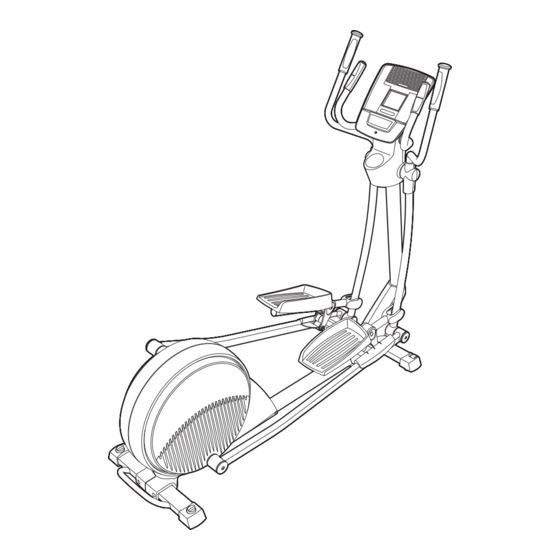
BEFORE YOU BEGIN Thank you for purchasing the NordicTrack E 7.3 ellip- manual. To help us assist you, note the product model ® tical. The E 7.3 elliptical provides an array of features number and serial number before contacting us. The... -
Page 5: Assembly
ASSEMBLY Assembly requires two persons. Place all parts of the elliptical in a cleared area and remove the packing materials. Do not dispose of the packing materials until assembly is completed. In addition to the included tool(s), assembly requires a Phillips screwdriver See the drawings below to identify the small parts needed for assembly. - Page 6 To make assembly easier, read the information on page 5 before you begin. While a second person lifts the rear of the Frame (1), attach the Rear Stabilizer (70) to the Frame with two M10 x 95mm Patch Screws (82). 2.
- Page 7 3. See the upper drawing. Orient the Upright (2) as shown. While a second person holds the Upright (2) near the Frame (1), connect the Upper Wire Harness (89) to the Wire Harness (42). Avoid pinching the wires See the lower drawing. Insert the Upright (2) into the Frame (1).
- Page 8 4. Identify the Right Pedal Bracket (21) and the Right Upper Body Leg (6) assembly, which is marked with a “Right” sticker. Then, identify the Right Pedal (13), which is marked with a “Right” sticker. Orient the Right Pedal (13), the Right Pedal Bracket (21), and the Right Upper Body Leg (6) as shown.
- Page 9 6. Apply grease to the axle on the right side of the Upright (2). Identify the Right Upper Body Arm (9), which is marked with a “Right” sticker, and orient it as shown. Slide the Right Upper Body Arm (9) onto the right side of the Upright (2).
- Page 10 8. See step 3. Tighten the five M10 x 20mm Patch Screws (79). Tip: Tighten the two rear Patch Avoid pinching Screws first and then tighten the other three the wires Patch Screws. Identify the Left and Right Front Shields (32, 37), which are marked with “Left”...
- Page 11 10. Identify the Right Handlebar (59), which is marked with a “Right” sticker, and orient it as shown. Have a second person hold the Right Handlebar (59) near the right side of the Upright Avoid pinching the (2). Locate the wire tie in the Upright. Tie the Pulse Wires (28) lower end of the wire tie to the right Pulse Wire (28).
- Page 12 12. While a second person holds the Console (4) near the Upright (2), connect the console wires to the Upper Wire Harness (89) and to the Avoid pinching the wires Pulse Wires (28). Insert the excess wires into the Upright (2) or Console Wires into the Console (4).
- Page 13 14. Press the Front Upright Cover (16) into the Rear Upright Cover (3). 15. Press two Outer Leg Covers (20) together around the Right Pedal Bracket (21) and the Right Upper Body Leg (6). Repeat this step on the other side of the elliptical.
-
Page 14: How To Use The Elliptical
HOW TO USE THE ELLIPTICAL HOW TO MOVE THE ELLIPTICAL HOW TO LEVEL THE ELLIPTICAL Due to the size and weight of the elliptical, moving If the elliptical it requires two persons. Stand in front of the ellipti- rocks slightly on cal, hold the upright, and place one foot against one of your floor during the front wheels. - Page 15 HOW TO EXERCISE ON THE ELLIPTICAL To mount the elliptical, hold the handlebars or the Upper Body Arms upper body arms and step onto the pedal that is in the lowest position. Then, step onto the other pedal. Push the pedals until they begin to move with a con- Handlebars tinuous motion.
- Page 16 CONSOLE DIAGRAM FEATURES OF THE CONSOLE For example, lose unwanted pounds with the 8-week Weight Loss workout. iFit workouts control the resis- The revolutionary console offers an array of features tance of the pedals while the voice of a personal train- designed to make your workouts more effective and er coaches you through your workouts.
- Page 17 HOW TO USE THE MANUAL MODE The lower right display—The 1. Begin pedaling or press any button on the lower right display console to turn on the console. can show the your pedaling speed (in A moment after you begin pedaling or press a but- miles or kilometers ton, a tone will sound, and the display will light.
- Page 18 5. Measure your heart rate if desired. If the display does not show your heart rate, make sure that your hands are positioned as described. If there are Be careful not to move your hands excessively or sheets of plastic to squeeze the metal contacts tightly.
- Page 19 HOW TO USE A TRAINER WORKOUT The resistance level for the first segment will appear in the display for a few seconds. During 1. Begin pedaling or press any button on the the workout, the workout profile will show your console to turn on the console.
- Page 20 HOW TO USE A CALORIE WORKOUT At the end of each segment of the workout, a series of tones will sound and the next segment of 1. Begin pedaling or press any button on the the profile will begin to flash. If a different resis- console to turn on the console.
- Page 21 HOW TO USE AN IFIT WORKOUT HOW TO USE THE SOUND SYSTEM iFit cards are available separately. To purchase iFit To play music or audio books through the consoleʼs cards, go to www.iFit.com or see the front cover of this sound system while you exercise, plug the included manual.
- Page 22 HOW TO CHANGE CONSOLE SETTINGS 3. Select a unit of measurement if desired. The console features a user mode that allows you to The console can show pedaling speed and dis- select a unit of measurement and a backlight option tance in either miles or kilometers.
-
Page 23: Maintenance And Troubleshooting
MAINTENANCE AND TROUBLESHOOTING Inspect and tighten all parts of the elliptical regularly. Remove the four Replace any worn parts immediately. indicated M4 x 38mm Screws To clean the elliptical, use a damp cloth and a small (86) from the amount of mild soap. IMPORTANT: To avoid damage Right Shield (45). - Page 24 HOW TO ADJUST THE REED SWITCH Locate the Reed Switch (58). Loosen, but do not remove, the M4 x 16mm Screw (92). If the console does not display correct feedback, the reed switch should be adjusted. To adjust the reed switch, you must remove the right pedal arm and the right pedal disc (see the instruc- tions below).
-
Page 25: Exercise Guidelines
EXERCISE GUIDELINES WARNING: Burning Fat—To burn fat effectively, you must exer- cise at a low intensity level for a sustained period of Before beginning this time. During the first few minutes of exercise, your or any exercise program, consult your physi- body uses carbohydrate calories for energy. - Page 26 SUGGESTED STRETCHES The correct form for several basic stretches is shown at the right. Move slowly as you stretch—never bounce. 1. Toe Touch Stretch Stand with your knees bent slightly and slowly bend forward from your hips. Allow your back and shoulders to relax as you reach down toward your toes as far as possible.
-
Page 27: Part List
PART LIST—Model No. NTCCEL70610.0 R0710A Key No. Qty. Description Key No. Qty. Description Frame Flywheel Upright Idler Rear Upright Cover C-magnet Console Resistance Motor Water Bottle Holder Motor Bracket Right Upper Body Leg Upper Arm Resistance Wheel Clamp Left Upper Body Arm Reed Switch/Wire Right Upper Body Arm Right Handlebar... - Page 28 Key No. Qty. Description Key No. Qty. Description Pedal Leg Cap M6 x 38mm Bolt Audio Cable M10 Split Washer Adjustment Cover Pulley Pedal Leg Bushing Right Pedal Arm Cover Adjustment Bushing – Userʼs Manual Adjustment Roller – Assembly Tool Roller Axle –...
-
Page 29: Exploded Drawing
EXPLODED DRAWING A—Model No. NTCCEL70610.0 R0710A... - Page 30 EXPLODED DRAWING B—Model No. NTCCEL70610.0 R0710A...
- Page 31 EXPLODED DRAWING C—Model No. NTCCEL70610.0 R0710A...
-
Page 32: Ordering Replacement Parts
ORDERING REPLACEMENT PARTS To order replacement parts, please see the front cover of this manual. To help us assist you, be prepared to provide the following information when contacting us: • the model number and serial number of the product (see the front cover of this manual) •...
Need help?
Do you have a question about the E73 and is the answer not in the manual?
Questions and answers