Advertisement
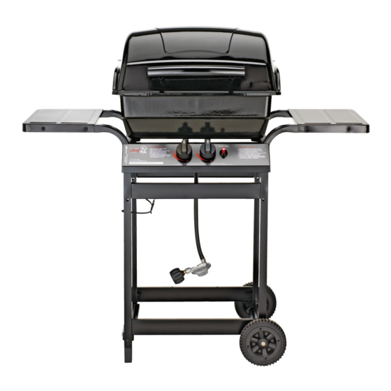
280 Barbecue
Assembly Manual
85-3001-8 (G20718) Propane
1 YeAr liMited WArrAntY
reAd And sAve MAnuAl for future reference.
if pre-assembled, leave this manual with unit for
consumer's future reference.
for product inquiries, parts, warranty and
troubleshooting support, please call 1-877-707-5463.
Manual Revision #: 23112009 PD
Advertisement
Table of Contents

Related Manuals for Master Chef 280 Barbecue


Summary of Contents for Master Chef 280 Barbecue
- Page 1 280 Barbecue Assembly Manual 85-3001-8 (G20718) Propane 1 YeAr liMited WArrAntY reAd And sAve MAnuAl for future reference. if pre-assembled, leave this manual with unit for consumer’s future reference. for product inquiries, parts, warranty and troubleshooting support, please call 1-877-707-5463.
-
Page 2: Hardware Pack
HARDWARE PACK tools needed for AsseMBlY KeY # description pArt nuMBer QuAntitY 1/4”-20UNC X35 Screw 20120-13035-036 • #2 Phillips screwdriver (long and short) 1/4”-20UNC X13 Screw 20120-13013-036 1/4”-20UNC Nut 31220-13000-036 • ¼” Slotted screwdriver (long and short) Bolt (for wheel) C423-0045-9084 •... - Page 3 PARts List (PRoPANE) foR 85-3001-8 (G20718) EXPLoDED DiAGRAM (PRoPANE) foR 85-3001-8 (G20718) KeY # QuAntitY description pArt no. Top lid assembly G208-0001-01 Top lid handle G305-0090-01 Upper hinge G206-0002-A1 SAFETY ASSEMBLY AND CARE MANUAL MANUAL Burner box assembly G205-0010-02 HARDWARE Lower hinge G206-0010-A1 PACK...
-
Page 4: Assembly Instructions
AssEMBLY iNstRUCtioNs AssEMBLY iNstRUCtioNs tWo people reQuired for All c. Assemble the wheels (DI) and the left bottom AsseMBlY steps. brace (DH) to the left cart legs (DA), at the same time, as shown. a. Front cart assembly: assemble two support braces (DE) to two cart legs (DA) as shown. -
Page 5: You Will Need
AssEMBLY iNstRUCtioNs AssEMBLY iNstRUCtioNs a. Attach the tank exclusion (DG) to the upper a. Position the valve assembly (CD) through the front support brace (DE) by hooking the end back of the control panel (CA), and assemble. of the tank exclusion into the hole provided, on the inside of the cart. -
Page 6: Side Shelf Assembly
AssEMBLY iNstRUCtioNs AssEMBLY iNstRUCtioNs side sHelf AsseMBlY Assemble the burner (BE) into the burner box assembly (BA), with the burner venturi tubes a. Assemble a side shelf (EA) to the left cart legs facing forward. (DA), as shown. YOU WILL NEED: b. - Page 7 AssEMBLY iNstRUCtioNs AssEMBLY iNstRUCtioNs Assemble the heat shield (BG) to the inside of the Assemble the upper hinge (AC) to the top lid as- left burner box support (DB), as shown. sembly (AA). YOU WILL NEED: YOU WILL NEED: cAution: sHArp edGes, WeAr sAfetY Gloves durinG AsseMBlY Assemble the top lid handle (AB) to the top lid...
- Page 8 AssEMBLY iNstRUCtioNs AssEMBLY iNstRUCtioNs Position the flame tamer (BD) into the burner box Hook the grease cup hook (DC) to the bottom of assembly (BA). the burner box assembly (BA), as shown. Place the grease cup (DD) into the grease cup hook Note: the flame tamer (BD) should be placed on (DC).
Need help?
Do you have a question about the 280 Barbecue and is the answer not in the manual?
Questions and answers