
Related Manuals for National Instruments PCI-6703


Summary of Contents for National Instruments PCI-6703
- Page 1 ™ PCI/PXI -6703/6704 User Manual DC Analog Output Devices for PCI/PXI/CompactPCI Bus Computers PCI/PXI-6703/6704 User Manual March 1999 Edition Part Number 322110B-01...
- Page 2 Switzerland 056 200 51 51, Taiwan 02 2377 1200, United Kingdom 01635 523545 For further support information, see the Technical Support Resources appendix. To comment on the documentation, send e-mail to techpubs@natinst.com. © Copyright 1998, 1999 National Instruments Corporation. All rights reserved.
-
Page 3: Important Information
Any action against National Instruments must be brought within one year after the cause of action accrues. National Instruments shall not be liable for any delay in performance due to causes beyond its reasonable control. The warranty provided herein does not cover damages, defects, malfunctions, or service failures caused by owner’s failure to follow the National Instruments... - Page 4 Conventions The following conventions are used in this manual: <> Angle brackets that contain numbers separated by an ellipsis represent a range of values associated with a bit or signal name—for example, DBIO<3..0>. ♦ The ♦ symbol indicates that the following text applies only to a specific product, a specific operating system, or a specific software version.
-
Page 5: Table Of Contents
Chapter 1 Introduction About the PCI/PXI-6703/6704 ..................1-1 What You Need to Get Started ..................1-2 Unpacking ........................1-2 Software Programming Choices ..................1-3 National Instruments Application Software ............1-3 NI-DAQ Driver Software ................1-4 Optional Equipment .......................1-5 Custom Cabling ....................1-5 Chapter 2 Installation and Configuration Software Installation ......................2-1... - Page 6 Contents Chapter 5 Calibration Self-Calibration ......................5-1 External Calibration....................... 5-1 Voltage Output Calibration ................... 5-3 Offset Adjustment ................... 5-3 Gain Adjustment ..................... 5-3 Current Output Calibration for the 6704 ............... 5-3 Offset Adjustment ................... 5-3 Gain Adjustment ..................... 5-4 Saving Calibration Values..................... 5-4 Appendix A Specifications Appendix B...
-
Page 7: About The Pci/Pxi-6703/6704
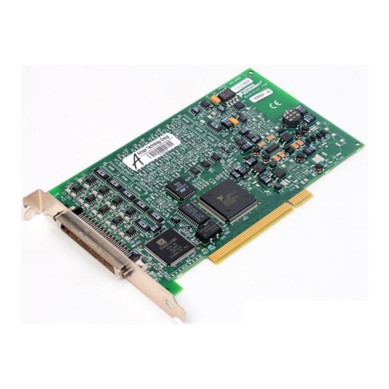
About the PCI/PXI-6703/6704 Thank you for purchasing a National Instruments 6703/6704 device. The 6703/6704 devices are precise DC setpoint devices for PCI and PXI. The 6703 devices have 16 voltage output channels. The 6704 devices have 16 voltage output channels and 16 current output channels for a total of 32 analog output channels. -
Page 8: What You Need To Get Started
Detailed specifications for the 6703/6704 devices are in Appendix A, Specifications. What You Need to Get Started To set up and use your 6703/6704 device, you will need the following: ❑ One of the following devices: • PCI-6703 • PXI-6703 • PCI-6704 • PXI-6704 ❑... -
Page 9: Software Programming Choices
ANSI standard C programming language. The LabWindows/CVI Data Acquisition Library, a series of functions for using LabWindows/CVI with National Instruments DAQ hardware, is included with the NI-DAQ software kit. The LabWindows/CVI Data Acquisition Library is functionally equivalent to the NI-DAQ software. -
Page 10: Ni-Daq Driver Software
NI-DAQ maintains a consistent software interface among its different versions so that you can change platforms with minimal modifications to your code. Whether you are using conventional programing languages or National Instruments application software, your application uses the NI-DAQ driver software, as illustrated in Figure 1-1. ComponentWorks,... -
Page 11: Optional Equipment
Chapter 1 Introduction Optional Equipment National Instruments offers a variety of products to use with your 6703/6704 device, including cables, connector blocks, and other accessories, as follows: • Cables and cable assemblies, shielded and ribbon • Connector blocks, shielded and unshielded screw terminals For more information about these products, refer to the National Instruments catalogue or website or call the office nearest you. -
Page 12: Installation And Configuration
Touch any metal part of your computer chassis to discharge any static electricity that might be on your clothes or body. Insert the PCI-6703/6704 into a 5 V PCI slot. Gently rock the device to ease it into place. Do not force the device into place. -
Page 13: Device Configuration
Chapter 2 Installation and Configuration Screw the mounting bracket of the PCI-6703/6704 device to the back panel rail of the computer. Visually verify the installation. Replace the cover. Plug in and turn on your computer. Your PCI-6703/6704 is installed. You are now ready to configure your hardware and software. -
Page 14: Signal Connections
National Instruments is liable for any damages resulting from any incorrect signal connections. I/O Connector Pin Assignments Figure 3-1 shows the I/O connector pin assignments for the 6703/6704 devices. © National Instruments Corporation PCI/PXI-6703/6704 User Manual... -
Page 15: Figure 3-1. I/O Connector Pin Assignments
Chapter 3 Signal Connections DGND DIO0 DGND DIO1 DGND DIO2 DIO3 DGND DIO4 DIO5 DGND DIO6 DGND DIO7 AGND 10 44 ICH31* VCH15 11 45 AGND15/AGND31 ICH30* 12 46 VCH14 AGND14/AGND30 13 47 ICH29* VCH13 14 48 AGND13/AGND29 ICH28* 15 49 VCH12 AGND12/AGND28 16 50... -
Page 16: Signal Connection Descriptions
These pins are connected to the 6703/6704 device analog ground plane. All 6703/6704 device ground planes connect to the computer system’s ground signal. 19, 43, 56 AGND Additional pins connected to analog ground. © National Instruments Corporation PCI/PXI-6703/6704 User Manual... -
Page 17: Analog Output Signal Connections
Warning Because 6703/6704 devices are not electrically isolated from high voltages, a load with high common-mode voltages can damage the devices. National Instruments is liable for any damages resulting from any such signal connections. Your 6703/6704 device has a bipolar voltage range of –10.1 to +10.1 V. -
Page 18: Current Output For The 6704
Warning Because 6704 devices are not electrically isolated from high voltages, a load with high common-mode voltages can damage the 6704 devices. National Instruments is liable for any damages resulting from any such signal connections. Figure 3-3 shows how to connect a current channel (ICH) as a current output. -
Page 19: Power-Up Condition
Chapter 3 Signal Connections voltage channel sharing the ground line. You can approach this problem in the following ways: – Use a shorter cable to minimize the impedance of the shared ground line. – Use separate wiring for VCH and ICH ground return to minimize common ground impedance. -
Page 20: Power-Up Condition
Under no circumstances should you connect these +5 V power pins directly to Warning ground or to any other voltage source on your 6703/6704 device or any other device. Doing so can damage your device and your computer system. National Instruments is liable for damage resulting from such a connection. -
Page 21: Hardware Overview
Circuit X nvRAM/ Control nvSRAM Addr/Ctrl Digital DIO Lines <7..0> Serial Number EEPROM Temperature Sensor +5 V 0.75 A Self-Resetting Circuit Breaker *No current circuits present on PCI/PXI-6703 Figure 4-1. PCI/PXI-6703/6704 Block Diagram © National Instruments Corporation PCI/PXI-6703/6704 User Manual... -
Page 22: Bus Interface Circuitry
Chapter 4 Hardware Overview Bus Interface Circuitry The bus interface circuitry monitors the PCI or PXI bus. If the bus address matches the 6703/6704 device’s address, the board is enabled and the corresponding register on the 6703/6704 is accessed. I/O Connector All user I/O is transmitted through a 68-pin connector. -
Page 23: Self-Calibration
To perform calibration, you need a voltage and current measuring device that is much more accurate than your 6703/6704 device. A DMM with an © National Instruments Corporation PCI/PXI-6703/6704 User Manual... -
Page 24: Table 5-1. 6703 Calibration Channel Numbers
Chapter 5 Calibration accuracy of at least 10 ppm will generally suffice, but be sure to check its specifications. Also, be sure that no other devices are connected to your 6703/6704 when you calibrate it to ensure that no ground loops can corrupt the calibration. -
Page 25: Voltage Output Calibration
To calibrate the offset, set one of the current output channels to 100 µA and measure it with a precise ammeter. Then, change the current offset channel value until the output is as close as possible to 100 µA. The current you © National Instruments Corporation PCI/PXI-6703/6704 User Manual... -
Page 26: Gain Adjustment
Chapter 5 Calibration write to the current offset channel will be close to 10 µA, and increasing it will lower the current you measure. Gain Adjustment To calibrate the gain, set the current output channel to a current near full-scale, such as 20 mA. Then, change the current gain channel value until the output that you measure is as close as possible to the current that you wrote to the output channel. -
Page 27: Appendix A Specifications
Monotonicity.......... 16 bits, guaranteed Voltage Output Range ............. ±10.1 V Output coupling........DC Output impedance ........0.1 Ω max Current drive .......... ±10 mA max Load capacitance........10,000 pF max Protection ..........Short-circuit to ground © National Instruments Corporation PCI/PXI-6703/6704 User Manual... - Page 28 Appendix A Specifications Absolute accuracy........±1 mV max Noise ............100 µV rms, DC to 1 MHz Power-up state ........Independent, user-defined values Current Output, 6704 Only Range ............0.1 to 20.2 mA Type ............Source, does not require external excitation source Output impedance........1 GΩ min Output compliance........0 to 10 V Absolute accuracy........±2 µA max Noise ............1 µA rms, DC to 1 MHz...
-
Page 29: Bus Interface
= 16 mA — Input leakage current — 10 µA Bus Interface Type ............Slave Power Requirement +5 V 6703 ..........700 mA 6704 ..........1 A +12 V............70 mA –12 V............70 mA © National Instruments Corporation PCI/PXI-6703/6704 User Manual... - Page 30 I/O connector. They assume that all voltage and current outputs are fully loaded. Physical Dimensions (not including connectors) PCI-6703/6704 ........9.9 by 17.5 cm (3.9 by 6.9 in.) PXI-6703/6704 ........10 by 16 cm (3.9 by 6.3 in.) I/O connector ..........68-pin male Environment Operating Temperature..........0°...
-
Page 31: Common Questions
Power Requirement section in Appendix A, Specifications. Installation and Configuration Which National Instruments document should I read first to get started using DAQ software? The release notes document for your application or driver software is always the best starting place. -
Page 32: Analog Output
Appendix B Common Questions What is the best way to test my device without having to program it? The Measurement and Automation Explorer has a Test panel with some excellent tools for doing simple functional tests of the device, such as testing the digital I/O lines. -
Page 33: Technical Support Resources
Technical Support Resources National Instruments offers technical support through electronic, fax, and telephone systems. The electronic services include our Web site, an FTP site, and a fax-on-demand system. If you have a hardware or software problem, please first try the electronic support systems. If the information... - Page 34 Telephone and Fax Support For telephone support in the United States, dial 512 795 8248. For telephone support outside the United States, contact your local branch office: Australia 03 9879 5166, Austria 0662 45 79 90 0, Belgium 02 757 00 20, Brazil 011 284 5011, Canada (Ontario) 905 785 0085, Canada (Québec) 514 694 8521, China 0755 3904939, Denmark 45 76 26 00, Finland 09 725 725 11, France 01 48 14 24 24,...
- Page 35 –6 milli- –3 kilo- mega- giga- Numbers/Symbols ° degrees – negative of, or minus Ω ohms percent ± plus or minus positive of, or plus amperes analog-to-digital ANSI American National Standards Institute © National Instruments Corporation PCI/PXI-6703/6704 User Manual...
- Page 36 (1) a plug-in data acquisition board, card, or pad that can contain multiple channels and conversion devices. Plug-in boards, PCMCIA cards, and devices such as the DAQPad-1200, which connects to your computer parallel port, are all examples of DAQ devices. digital input/output PCI/PXI-6703/6704 User Manual © National Instruments Corporation...
- Page 37 Integral Nonlinearity—a measure in LSB of the worst-case deviation from the ideal A/D or D/A transfer characteristic of the analog I/O circuitry © National Instruments Corporation PCI/PXI-6703/6704 User Manual...
- Page 38 NI-DAQ National Instruments driver software for DAQ hardware PCI/PXI-6703/6704 User Manual © National Instruments Corporation...
- Page 39 Real-Time System Integration seconds settling time the amount of time required for a voltage to reach its final value within specified limits slot a position where a module can be inserted into the PCI bus © National Instruments Corporation PCI/PXI-6703/6704 User Manual...
- Page 40 PC, that has the functionality of a classic stand-alone instrument (2) a LabVIEW software module (VI), which consists of a front panel user interface and a block diagram program watts PCI/PXI-6703/6704 User Manual © National Instruments Corporation...
- Page 41 DGND signal (table), 3-3 current output calibration for 6704, digital I/O 5-3 to 5-4 common questions, B-2 gain adjustment, 5-4 example connections (figure), 3-6 offset adjustment, 5-4 hardware overview, 4-2 power-up condition, 3-7 © National Instruments Corporation PCI/PXI-6703/6704 User Manual...
- Page 42 (table), 3-3 e-mail support, C-1 environment specifications, A-4 LabVIEW and LabWindows/CVI software, 1-3 equipment, optional, 1-5 National Instruments application software, fax and telephone support numbers, C-2 1-3 to 1-4 Fax-on-Demand support, C-1 NI-DAQ driver software, 1-4 frequently asked questions. See questions nonvolatile RAM/DAC control, 4-2 about PCI/PXI-6703/6704.
- Page 43 3-7 signal connections, 3-4 software installation, 2-1 specifications, A-1 to A-2 software programming choices, 1-3 to 1-4 VCH connection as voltage output National Instruments application (figure), 3-4 software, 1-3 to 1-4 © National Instruments Corporation PCI/PXI-6703/6704 User Manual...
- Page 44 Index Web site support, C-1 PCI/PXI-6703/6704 User Manual © National Instruments Corporation...
Need help?
Do you have a question about the PCI-6703 and is the answer not in the manual?
Questions and answers