
Related Manuals for Notifier NFS-320


Summary of Contents for Notifier NFS-320
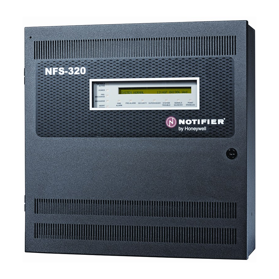
- Page 1 Fire Alarm Control Panel NFS-320/E/C, NFS-320SYS/E Operations Manual Document 52747 06/16/2011 Rev: P/N 52747:E1 ECN 11-336...
-
Page 2: Fire Alarm System Limitations
warning of fires caused by arson, children playing with matches (especially in bedrooms), smoking in bed, and violent explosions (caused by escaping gas, improper storage of Limit-C1-2-2007 flammable materials, etc.). NFS-320/E/C, NFS-320SYS/E Operations Manual — P/N 52747:E1 06/16/2011... -
Page 3: Installation Precautions
HARSH™, NIS™, and NOTI•FIRE•NET™ are all trademarks; and Acclimate® Plus, FlashScan®, NION®, NOTIFIER®, ONYX®, ONYXWorks®, UniNet®, VeriFire®, and VIEW® are all registered trademarks of Honeywell International Inc. Echelon® is a registered trademark and LonWorks™ is a trademark of Echelon Corporation. - Page 4 •Your suggestion for how to correct/improve documentation Send email messages to: FireSystems.TechPubs@honeywell.com Please note this email address is for documentation feedback only. If you have any technical issues, please contact Technical Services. NFS-320/E/C, NFS-320SYS/E Operations Manual — P/N 52747:E1 06/16/2011...
-
Page 5: Table Of Contents
3.11: Active Trouble Monitor Mode of Operation....................29 3.11.1: How the Control Panel Indicates an Active Trouble Monitor............29 3.11.2: How to Respond to an Active Trouble Monitor ................30 3.12: Output Circuit Trouble Mode of Operation ....................30 3.12.1: Overview ............................30 NFS-320/E/C, NFS-320SYS/E Operations Manual — P/N 52747:E1 06/16/2011... - Page 6 C.3: Using the CRT-2 for Read Status ........................62 C.3.1: Overview ............................62 C.3.2: Accessing Read Status Options......................62 C.3.3: Read Point ............................63 C.3.4: Display Devices in Alarm or Trouble ....................63 C.3.5: Display All Programmed Points .......................64 C.3.6: Step-through History.........................64 NFS-320/E/C, NFS-320SYS/E Operations Manual — P/N 52747:E1 06/16/2011...
- Page 7 C.4.6: Clear the Entire History Buffer......................66 C.4.7: Set the Pre-Alarm for Alert or Action....................67 Appendix D: Point and System Troubles Lists ..............68 D.1: Point (Device) Troubles ..........................68 D.2: System Troubles............................69 Index............................72 NFS-320/E/C, NFS-320SYS/E Operations Manual — P/N 52747:E1 06/16/2011...
-
Page 8: Section 1: General Information
Table 1.1 Typographic Conventions in this Manual NOTE: In this manual, the term NFS-320 is used to refer to the NFS-320, NFS-320E, and NFS-320C, NFS-320SYS and NFS-320SYS/E unless otherwise noted. NFS-320/E/C, NFS-320SYS/E Operations Manual — P/N 52747:E1 06/16/2011... -
Page 9: 3: Supplemental Information
DPI-232 Direct Panel Interface Manual 51499 TM-4 Installation Document (Reverse Polarity Transmitter) 51490 UDACT Manual (Universal Digital Alarm Communicator/Transmitter) 50050 FireVoice-25/50 & FireVoice-25/50ZS Manual 52290 RA100Z Remote LED Annunciator Installation Document I56-0508 Table 1.2 Supplemental Documentation NFS-320/E/C, NFS-320SYS/E Operations Manual — P/N 52747:E1 06/16/2011... -
Page 10: 4: Shortcuts To Operating Functions
1.3 Introduction to the Control Panel The NFS-320 is a modular, intelligent Fire Alarm Control Panel (FACP) with features suitable for most applications. Following is a list of operating features available. •... -
Page 11: Section 2: Use Of The Controls
Cursor movement (arrow) keys, (Refer to page 14 key, and key. (Refer to page 14 ENTER Figure 2.1 NFS-320 Control Panel Keys and Indicators 2.2 System Status Indicator LEDs The control panel contains 12 labeled LEDs described in Table 2.1. Indicator Color... -
Page 12: Control Keys
Changes all active LED indicators from flashing to steady • Sends an Acknowledge message to the History buffer and installed printers, CRT-2 terminals, and FDU-80 annunciators • Sends a signal to silence the sounders on the FDU-80 and ACS annunciators NFS-320/E/C, NFS-320SYS/E Operations Manual — P/N 52747:E1 06/16/2011... -
Page 13: 2: Signal Silence
NOTE: Trouble conditions will not clear and re-report upon reset. NOTE: If Local Control is set to “0” (NO), the FACP will not respond to SYSTEM RESET NFS-320/E/C, NFS-320SYS/E Operations Manual — P/N 52747:E1 06/16/2011... -
Page 14: 4: Drill
• Cursor movement keys: key, key, key, LEFT ARROW RIGHT DOWN • Alphabetic and numeric keys, with selection key LOWER CASE Shown below is the Programming Keypad, with descriptions for the keys. NFS-320/E/C, NFS-320SYS/E Operations Manual — P/N 52747:E1 06/16/2011... - Page 15 Arrow keys – press to move the cursor one place in the direction of the arrow key – press to exit a selection or move the cursor one place to the left Figure 2.2 Programming Keypad NFS-320/E/C, NFS-320SYS/E Operations Manual — P/N 52747:E1 06/16/2011...
-
Page 16: Section 3: Operation Of The Control Panel
S Y S T E M N O R M A L 0 1 : 5 6 P 0 4 1 5 1 1 T u e Figure 3.1 Sample System Normal Message NFS-320/E/C, NFS-320SYS/E Operations Manual — P/N 52747:E1 06/16/2011... -
Page 17: Fire Alarm Mode Of Operation
SCROLL DISPLAY FIRE LED will change from flashing to steady. ALARM The control panel will send an acknowledge message to the LCD display, history buffer, and installed printers, FDU-80 annunciators, and CRT-2s. NFS-320/E/C, NFS-320SYS/E Operations Manual — P/N 52747:E1 06/16/2011... -
Page 18: 3: Interpreting Fire Alarm Type Codes
LED and activates CBE FIRE ALARM SMOKE(DUCT I) Indicates activation of a duct ion smoke detector Lights LED and activates CBE FIRE ALARM Table 3.1 Fire Alarm Type Codes (1 of 2) NFS-320/E/C, NFS-320SYS/E Operations Manual — P/N 52747:E1 06/16/2011... - Page 19 CBE, CO alarm will activate sixth CBE zone only (sixth CBE zone programmable via VeriFire Tools) *FlashScan mode only Table 3.1 Fire Alarm Type Codes (2 of 2) NFS-320/E/C, NFS-320SYS/E Operations Manual — P/N 52747:E1 06/16/2011...
-
Page 20: Carbon Monoxide (Co) Alarm Mode Of Operation
SYSTEM RESET control panel to normal operation (indicated by the “System Normal” message). The control panel sends a “System Normal” message to the LCD display, History buffer, installed printers, FDU-80 annunciators, and CRT-2s. NFS-320/E/C, NFS-320SYS/E Operations Manual — P/N 52747:E1 06/16/2011... -
Page 21: 3: Interpreting Co Alarm/Supervisory Type Id Codes
Sends a Trouble message to the LCD display, history buffer and installed printers, FDU-80 annunciators, and CRT-2s. NOTE: If a fire alarm exists when a trouble exists, the LED lights, but the Alarm SYSTEM TROUBLE message appears in the LCD display. NFS-320/E/C, NFS-320SYS/E Operations Manual — P/N 52747:E1 06/16/2011... -
Page 22: 2: How To Respond To A System Trouble
If multiple trouble conditions exist in the system, the LCD and optional CRT-2 and FDU-80 annunciators display automatically step through each trouble every 3 seconds in the following order: Alarms, in order of address Supervisory, in order of address Troubles, in order of address NFS-320/E/C, NFS-320SYS/E Operations Manual — P/N 52747:E1 06/16/2011... -
Page 23: Security Alarm Mode Of Operation
LED from flashing to steady—regardless of the number of troubles, alarms, SECURITY supervisory, and security signals. The control panel sends a Security message to the History buffer and installed printers, FDU-80 annunciators, and CRT-2s. Correct the condition that activated the Security point. NFS-320/E/C, NFS-320SYS/E Operations Manual — P/N 52747:E1 06/16/2011... -
Page 24: 3: Interpreting Security Type Codes
0 3 : 1 9 P 0 4 1 5 1 1 2 M 1 4 7 Extended 12 character Device address Zone Time and date of trouble custom label Figure 3.10 Sample Supervisory Signal Message NFS-320/E/C, NFS-320SYS/E Operations Manual — P/N 52747:E1 06/16/2011... -
Page 25: 2: How To Respond To An Active Supervisory
The Type Code that displays in the Supervisory message indicates the function of the point that initiates the Supervisory. For example, a monitor module with a Type Code means that the TAMPER monitor module connects to a tamper switch. NFS-320/E/C, NFS-320SYS/E Operations Manual — P/N 52747:E1 06/16/2011... -
Page 26: Pre-Alarm Warning Mode Of Operation
Displays a pre alarm status banner, the Type Code of the detector, and the Pre-Alarm level (Alert or Action) on the LCD display, along with information specific to the device as shown in Figure 3.11. NFS-320/E/C, NFS-320SYS/E Operations Manual — P/N 52747:E1 06/16/2011... -
Page 27: 2: How To Respond To A Pre-Alarm Warning
Use the Pre-Alarm function if you want to get an early warning of incipient or potential fire conditions. The Pre-Alarm function provides one of two levels of Pre-Alarm as follows: NOTE: For detailed information on Pre-Alarm applications, refer to the NFS-320 Programming Manual. •... -
Page 28: Disabled Points Mode Of Operation
Resets control panel SIL SWITCH Performs Signal Silence function Turns off all activated silenceable outputs ABORT SWITCH Indicates Active at the panel Aborts activation of a releasing zone Table 3.5 Non-Alarm Type Codes NFS-320/E/C, NFS-320SYS/E Operations Manual — P/N 52747:E1 06/16/2011... -
Page 29: 2: How The Control Panel Indicates An Active Fire Control
Figure 4 Sample Trouble Monitor Point Message • The monitor module is non-latching: the module will return to normal when the trouble condition no longer exists. • The monitor modules activate Control-by-Event NFS-320/E/C, NFS-320SYS/E Operations Manual — P/N 52747:E1 06/16/2011... -
Page 30: 2: How To Respond To An Active Trouble Monitor
Output that will activate upon receipt of an alarm condition, and remain in the alarm state until all alarms have been acknowledged. CONTROL NAC** Supervised NAC Table 3.7 Control Module and NAC Circuit Trouble Type Codes (1 of 2) NFS-320/E/C, NFS-320SYS/E Operations Manual — P/N 52747:E1 06/16/2011... -
Page 31: 2: How The Control Panel Indicates A Nac Trouble
0 9 : 3 8 A 0 1 1 5 1 1 1 M 0 4 4 Device Address Type of Trouble Time and date of trouble Figure 3.2 Sample of a Control/Relay Module in Trouble Message NFS-320/E/C, NFS-320SYS/E Operations Manual — P/N 52747:E1 06/16/2011... -
Page 32: 4: How To Respond To A Nac Or Control/Relay Trouble
A timer that functions like pressing the key. When the Auto Silence Timer reaches SIGNAL SILENCE its programmed value (600-900 seconds), the control panel automatically shuts off all active outputs programmed as silenceable. NFS-320/E/C, NFS-320SYS/E Operations Manual — P/N 52747:E1 06/16/2011... -
Page 33: Waterflow Circuit Operation
If a monitor module programmed with a Type Code initiates a fire alarm, the control WATERFLOW panel disables the key and the Auto Silence Timer. Refer to the NFS-320 SIGNAL SILENCE Installation Manual for information on Waterflow circuits. 3.15 Style 6 and Style 7 Operation Style 6 and Style 7 are supervised methods of communicating with addressable devices. -
Page 34: Section 4: Read Status Operation
P R N T P O I N T = 1 H I S T = 3 A L A R M H I S T = 5 < E N T E R > NFS-320/E/C, NFS-320SYS/E Operations Manual — P/N 52747:E1 06/16/2011... -
Page 35: Viewing And Printing A Read Status
“How to View Read Status for a Releasing Zone (R0-R9)” on page 40 System Functions “How to Read Status for System Functions” on page 40 Annunciator Selections “How to Read Status for Annunciator Selections” on page 41 NFS-320/E/C, NFS-320SYS/E Operations Manual — P/N 52747:E1 06/16/2011... - Page 36 Alarm sensitivity level Alarm Verification Time Pre-Alarm sensitivity level (in seconds) Alarm Verification selection: V on; * off Multidetector selection: A, B, C, or * (not selected) Figure 4.1 Sample Detector Read Status Display NFS-320/E/C, NFS-320SYS/E Operations Manual — P/N 52747:E1 06/16/2011...
- Page 37 Pre-Alarm sensitivity level The Pre-Alarm Sensitivity (1-9; 0 = Pre-Alarm not used) entered in the Detector Settings Screen. NOTE: Refer to “Detector Sensitivity Settings” in the NFS-320 Programming Manual for more information on the Pre-Alarm and Alarm Sensitivity settings •...
- Page 38 CBE List Only the first zone in the NAC’s CBE list will be displayed here. • Device Address The address of the NAC (01-04) • Switch Inhibit A selection for disabling the switch function for the control/relay or transponder output circuit. (I=on; *=off). NFS-320/E/C, NFS-320SYS/E Operations Manual — P/N 52747:E1 06/16/2011...
- Page 39 O F F C O D I N G F U N C T I O N C O D E T Y P E M A R C H T I M E Code Type selection Indicates Special Zone F8 for Special Zone F8 Figure 4.5 Sample Special Zone Read Status Display NFS-320/E/C, NFS-320SYS/E Operations Manual — P/N 52747:E1 06/16/2011...
- Page 40 LocM – terminal connected to control Terminal) panel but requires password for operation. RemT – terminal connected through a modem for Read Status operations only. Table 4.1 System Function Parameters (1 of 2) NFS-320/E/C, NFS-320SYS/E Operations Manual — P/N 52747:E1 06/16/2011...
- Page 41 Figure 4.10 System Function Selection 5 Screen F L A S H S C A N L I D E T L I M O D Figure 4.11 System Function Selection 6 Screen NFS-320/E/C, NFS-320SYS/E Operations Manual — P/N 52747:E1 06/16/2011...
- Page 42 Figure 4.14 Annunciator Selection Screen 1 Example NOTE: An ACS selection marked with an asterisk (*) indicates no annunciator selection. The figure above shows annunciator selections for addresses A1-A3 (addresses A4-A10, marked with asterisks, are not selected) NFS-320/E/C, NFS-320SYS/E Operations Manual — P/N 52747:E1 06/16/2011...
- Page 43 Annunciators set to annunciator address 2 (A2) display the status of intelligent modules 1-64 on SLC-1 (ACS Selection Group C) How to Read Status for Battery Levels Pressing the key on the NFS-320 keyboard displays information concerning the BATTERY LEVEL state of the battery. A sample LCD display is shown below.
-
Page 44: 2: How To View Read Status For Event And Alarm History
G R O U N D F A U L T 0 1 : 4 6 P 0 1 1 5 0 8 T u e Time and date of the event Figure 4.17 Sample Trouble Event Display NFS-320/E/C, NFS-320SYS/E Operations Manual — P/N 52747:E1 06/16/2011... -
Page 45: 3: How To Print Points, Event And Alarm History
NOTE: Before printing, make sure your control panel is connected to a compatible printer and the printer is configured according to the manufacturer’s specifications, and that the correct baud rate is selected at the panel. NFS-320/E/C, NFS-320SYS/E Operations Manual — P/N 52747:E1 06/16/2011... - Page 46 A sample printout of two alarm events in the History buffer using the Print Alarm History option. ********************ALARM HISTORY START **************************************** ALARM: SMOKE (ION) DETECTOR ADDR 1D075 Z002 02:28P 011508 1D075 ALARM: SMOKE (ION) DETECTOR ADDR 1D076 Z002 02:28P 011508 1D076 ******************* PRINT END **************************************** NFS-320/E/C, NFS-320SYS/E Operations Manual — P/N 52747:E1 06/16/2011...
-
Page 47: 4: How To View And Print Hidden Event And Alarm History
46 Read Hidden History “How to View Read Status for Event History” on page 44 Print Hidden History “How to Print Event History” on page 46 Table 4.3 Hidden History Selections NFS-320/E/C, NFS-320SYS/E Operations Manual — P/N 52747:E1 06/16/2011... - Page 48 Notes NFS-320/E/C, NFS-320SYS/E Operations Manual — P/N 52747:E1 06/16/2011...
-
Page 49: Appendix A: Special Zone Operation
This section contains descriptions of each Releasing Function option and an example of how Releasing Zone options work. For instructions on programming Releasing Functions, refer to the NFS-320 Programming Manual. Each Releasing Zone includes the following releasing options:... -
Page 50: A.2.2: How To View Releasing Zone Selections
F R O N T H A L L W A Y N O . 3 R 1 _ _ _ _ _ _ _ _ I * * B 0 3 CBE list = R1 NFS-320/E/C, NFS-320SYS/E Operations Manual — P/N 52747:E1 06/16/2011... - Page 51 • An alarm from 2D102 and 2D103 – detectors mapped to different zones, but both list ZR1 in their CBE. Cross=H Activation of heat detector 2D104 and one smoke detector (2D101, 2D102, or 2D103). Table A.2 Example of Cross Zone Selections NFS-320/E/C, NFS-320SYS/E Operations Manual — P/N 52747:E1 06/16/2011...
-
Page 52: A.3: Time, Date, And Holiday Functions
You can use the Read Status Entry option to view the current selection for the Time function. To do so, press the following keys in sequence: NOTE: For instructions on programming the Time function, refer to the NFS-320 Programming Manual. -
Page 53: A.3.3: How To View Holiday Function Selections
F5 or F6. All smoke detectors with a CBE list containing F5 or F6 switch to their lowest sensitivity (AL:9) within the times specified for the days of the week listed in ZF5 or ZF6. Refer to “Intelligent Sensing Applications” in the NFS-320 Programming Manual for details on setting detector sensitivity. -
Page 54: A.4: Nac Coding
You can use the Read Status Entry option to view the current selection for the Coding function. To do so, press the following keys in sequence: NOTE: For instructions on programming the Coding function, refer to the NFS-320 Programming Manual. -
Page 55: A.4.3: How To Respond To An Alarm With Coding
An illustration of Presignal and PAS timing. Presignal Delay Timer (60-180) PAS (15s) If PAS=Y, alarm activates outputs if not acknowledged Initial alarm Alarm activates outputs, annunciation if panel is not reset. Figure A.7 Presignal and PAS Time NFS-320/E/C, NFS-320SYS/E Operations Manual — P/N 52747:E1 06/16/2011... -
Page 56: A.5.3: How To View Presignal And Pas Selections
You can use the Read Status Entry option to view the current selection for the Presignal function. To do so, press the keys in sequence: NOTE: For instructions on programming the Presignal function, refer to the NFS-320 Programming Manual. The LCD display shows the current selections for the Presignal function. The figure below shows a... -
Page 57: A.5.5: How To Respond To An Alarm With Presignal Delay Timer (Pas Selected)
The Manual Evacuate screen and Alarm screen display alternately at 3-second intervals. If the Presignal Delay Timer reaches its programmed value, without operator intervention, the control panel activates all outputs programmed to F0. NFS-320/E/C, NFS-320SYS/E Operations Manual — P/N 52747:E1 06/16/2011... -
Page 58: Appendix B: Intelligent Detector Functions
Appendix B: Intelligent Detector Functions NOTE: For instructions on selecting Intelligent Detector Functions, refer to the NFS-320 Programming Manual. Descriptions for Intelligent Detector Functions Function Description Analog Display The control panel reads and displays analog information from the 318 analog detectors (159 per SLC). The display shows the sensed air at the detector as a percentage of the alarm threshold for each detector. - Page 59 Notes NFS-320/E/C, NFS-320SYS/E Operations Manual — P/N 52747:E1 06/16/2011...
-
Page 60: Appendix C: Remote Terminal Access
The control panel can communicate with a remote terminal or computer connected to the EIA-232 PC/Terminal port. Refer to the NFS-320 Installation Manual for installation information. NOTE: See the NFS-320 Programming Manual for instructions on enabling the CRT. This port may be set up for interactive operation or for monitoring only. Interactive operation requires that all equipment be UL-listed under UL Standard for Safety UL 864 and be installed and set up as directed under Local Terminal Mode (LocT) or Local Monitor Mode (LocM). -
Page 61: C.2.2: Local Monitor Mode (Locm)
Use with UL ITE-listed terminals, including personal computers with the VeriFire™ Tools or terminal emulation software. Intended for terminals connected through modems, including FSK modems connected through a public switched telephone network. NFS-320/E/C, NFS-320SYS/E Operations Manual — P/N 52747:E1 06/16/2011... -
Page 62: C.3: Using The Crt-2 For Read Status
C.3 Using the CRT-2 for Read Status C.3.1 Overview This section shows how to perform Read Status functions from a CRT-2. NOTE: See the NFS-320 Programming Manual for instructions on enabling the CRT port. For more information see the “Read Status” section of this manual. Function Lets you... -
Page 63: C.3.3: Read Point
TROUBL HEAT(FIXED) DETECTOR ADDR 1D006 INVREP 01;09P 041608 1D006 TROUBL MONITOR MODULE ADDR 1M041 INVREP 01;09P 041608 1M041 TROUBL IN SYSTEM GROUND FAULT 01;09P 041608 Wed TROUBL IN SYSTEM BATTERY 01;09P 041608 Wed NFS-320/E/C, NFS-320SYS/E Operations Manual — P/N 52747:E1 06/16/2011... -
Page 64: C.3.5: Display All Programmed Points
This section shows how to Alter Status functions from a CRT-2. NOTE: The panel must be in Local Terminal Mode (LocT) or Local Monitor Mode (LocM). NOTE: See the NFS-320 Programming Manual for instructions on enabling the CRT port. NFS-320/E/C, NFS-320SYS/E Operations Manual — P/N 52747:E1 06/16/2011... -
Page 65: C.4.2: Accessing Alter Status Options
Enter the first letter to read one of the following, using upper case letters: Detector = D Module = M NAC = P Zone - Z Enter the address or number of the device. Press and a display similar to the following will appear. ENTER NFS-320/E/C, NFS-320SYS/E Operations Manual — P/N 52747:E1 06/16/2011... -
Page 66: C.4.4: Change Alarm And Pre-Alarm Levels
Press <3>< > ENTER STATUS CHANGE Clear verify count 08:29A Tue 01/15/08 C.4.6 Clear the Entire History Buffer Clear History lets you clear the entire History buffer. Press <4>< > ENTER ***************History Clear************************* NFS-320/E/C, NFS-320SYS/E Operations Manual — P/N 52747:E1 06/16/2011... -
Page 67: C.4.7: Set The Pre-Alarm For Alert Or Action
“Alert” to “Action” as follows: Press <5>< > ENTER Set Pre-alarm Alert (NO)/Action(YES). Type N or Y then Enter STATUS CHANGE Change Alert/Action 08:29A Tue 01/15/08 Press <Y>< > ENTER Pre-alarm now set for ACTION NFS-320/E/C, NFS-320SYS/E Operations Manual — P/N 52747:E1 06/16/2011... -
Page 68: Appendix D: Point And System Troubles Lists
The detector should be removed and replaced by an capabilities. authorized service representative. *This trouble may be fire panel or backup battery related. Test and replace backup batteries if necessary. Table D.1 Point (Device) Troubles (1 of 2) NFS-320/E/C, NFS-320SYS/E Operations Manual — P/N 52747:E1 06/16/2011... -
Page 69: D.2: System Troubles
The annunciator at address x is in trouble. Determine if the ACS module is functional, correctly installed, and configured properly. AUXILIARY TROUBLE An auxiliary device connected to the NFS-320 at J6 is Check the wiring and source. in trouble or the cable is missing. BASIC WALK TEST A Basic Walk Test is in progress. - Page 70 UL 864 Ninth edition, and can result in the panel displaying a charger fail. Batteries should be tested and replaced as necessary before repairing or replacing the panel. NFS-320/E/C, NFS-320SYS/E Operations Manual — P/N 52747:E1 06/16/2011...
- Page 71 Notes NFS-320/E/C, NFS-320SYS/E Operations Manual — P/N 52747:E1 06/16/2011...
-
Page 72: Index
Functions 58 Type Codes 30 Read Status 37 NAC, read status 38 supervisory alarm type codes 26 Non-Alarm Points 28 Disabled Points 28 Non-Fire Point, active, panel indication 29 Discharge LED 12 NFS-320/E/C, NFS-320SYS/E Operations Manual — P/N 52747:E1 06/16/2011... - Page 73 Releasing Zone (R0-R9), read status 40 When used for CO2 releasing applica- – Releasing Zones (R0-R9) 49 tions... 16 –?? Remote Terminal Access 60 Waterflow Circuit operation 33 RemT, Remote Terminal Mode 60 NFS-320/E/C, NFS-320SYS/E Operations Manual — P/N 52747:E1 06/16/2011...
- Page 74 X–X Index XP6-C 30 XPC transponder points 30 NFS-320/E/C, NFS-320SYS/E Operations Manual — P/N 52747:E1 06/16/2011...
- Page 75 Manufacturer's Return Material Authorization form. The replacement part shall come from Manufacturer's stock and may be new or refurbished. THE FOREGOING IS DISTRIBUTOR'S SOLE AND EXCLUSIVE REMEDY IN THE EVENT OF A WARRANTY CLAIM. Warn-HL-08-2009.fm NFS-320/E/C, NFS-320SYS/E Operations Manual — P/N 52747:E1 06/16/2011...
- Page 76 World Headquarters 12 Clintonville Road Northford, CT 06472-1610 USA 203-484-7161 fax 203-484-7118 www.notifier.com...
Need help?
Do you have a question about the NFS-320 and is the answer not in the manual?
Questions and answers