
Related Manuals for Q-See QC818


Summary of Contents for Q-See QC818
- Page 1 User Manual QC SERIES NVRS POWER ENTER SHIFT QC828 NVR 8 Channels H.264 NETWORK VIDEO RECORDERS 720P and 1080P Recording Options...
-
Page 2: About This Manual
Additionally, our products also come with a free exchange We encourage you to visit our website at www.Q-see.com to check for the latest firmware policy that covers all manufacturing defects for one month from the date of purchase. -
Page 3: Table Of Contents
2. CONNECTIONS AND CONTROLS Online Users 2.1 Connections Remote Device Info QC804, 808 and 8016 Network Resource Info QC814 4.3 Setting Menu QC824 RS232 QC818 Alarm QC828 Network 2.2 Mouse Control Virtual Keyboard Display Default 2.3 Remote Control 4.5 Remote Device 2.4 IP Cameras... -
Page 4: Introduction
INTRODUCTION CHAPTER 1 7.1 Installation/Removal To prevent damage to your Q-See product or injury to yourself or to others, read and understand the following safety precautions in their entirety before installing or using this APPENDIX equipment. Keep these safety instructions where all those who use the product will read them. -
Page 5: Features And Specifications
FEATURES AND SPECIFICATIONS Connect to a TV or PC Monitor Easily Your NVR (Network Video Recorder) contains professional-grade features and flexibility that This system comes with VGA and HDMI video output ports to allow you to connect to a allows the do-it-yourselfer to easily setup and maintain a reliable and secure security system computer monitor or HD display for viewing purposes. -
Page 6: Connections And Controls
CONNECTIONS AND CONTROLS CHAPTER 2 2.1 CONNECTIONS QC804, 808 AND 8016 Rear Panel Front Panel AUDIO VIDEO OUT RS232 POWER DC 12V DC 48V ENTER SHIFT QC808 NVR 8 Channels 10 11 10 11 12 Number Item Function Number Item Function Channel These lights will illuminate to indicate that a particular channel... -
Page 7: Qc814
QC814 QC824 Front Panel Front Panel Rear Panel Rear Panel DC 12V DC 48V DC 48V DC 12V Number Item Function Number Item Function These show the status of the network connection, power and These show the status of the network connection, power and Status Lights hard drive respectively. -
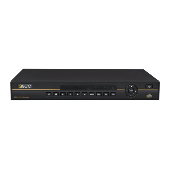
Page 8: Qc818
Front Panel Rear Panel AUDIO VIDEO OUT RS232 POWER DC 48V DC 12V ENTER SHIFT QC818 NVR 8 Channels 10 11 12 10 11 Number Item Function Number Item Function POE Power 48V power input for the Power Over Ethernet (POE) block. -
Page 9: Qc828
QC828 Front Panel Rear Panel AUDIO VIDEO OUT RS232 POWER DC 48V DC 12V ENTER SHIFT QC828 NVR 8 Channels 10 11 10 11 Number Item Function Number Item Function POE Power 48V power input for the Power Over Ethernet (POE) block. Channel These lights will illuminate to indicate that a particular channel Input... -
Page 10: Mouse Control
2.2 MOUSE CONTROL VIRTUAL KEYBOARD Whenever a menu field requires text - such as a password, new user name, or other setting This NVR can be controlled through the USB mouse, the remote control or by using the buttons on the front panel of the device. We have found that the majority of our customers - clicking on that field will bring up the virtual keyboard. -
Page 11: Remote Control
2.3 REMOTE CONTROL The buttons on the Remote Control operate in the same manner as on a conventional video player remote. Some buttons have multiple functions depending on which menu is being accessed. NOTE! The QC814 and QC824 cannot be operated using a remote control and your NVR will not include one. -
Page 12: Ip Cameras
2.4 IP CAMERAS If you are unsure, and if your camera has infrared LEDs, you may cup your hand over the lens area to activate the infrared night vision mode. You will see a faint red glow from the LEDs Internet Protocol (IP) or Network cameras differ from conventional video cameras in that each confirming that the camera has power. -
Page 13: Adding And Removing Cameras In Your Display
Live View is the default mode for the NVR. It will display the video feeds from up to four, eight IP cameras are available from Q-See in the two common high definition standards - 720P or 16 cameras depending on model. You do not need to be logged into the NVR to view and 1080P. -
Page 14: Navigation Bar
Clicking on any one screen in multi-view mode will bring that screen to full-screen single-view SHORTCUT VIDEO CONTROLS mode. The exception is in eight-view where clicking on one of the smaller displays will move it When the mouse cursor is in the top-center portion of a channel with a live video stream, a to the larger display. -
Page 15: Login, Logout And Main Menu
3.3 LOGIN, LOGOUT AND MAIN MENU Once you have logged in, the NVR will display one or more camera channels in Live View. How many channels are displayed will depend on how many cameras you have connected as well as what multi-view mode you have chosen. LOGIN After a period of inactivity –... -
Page 16: Main Menu
3.4 RECORDING MAIN MENU After logging in, you can view – and access - the NVR’s functions through the Main Menu. Your NVR is factory set to record when motion is detected. Most users prefer this as it means that it is easier to locate an event using the Search function (see Section 3.5) and it will take MAIN MENU longer before the DVR will need to overwrite older files on the hard drive. -
Page 17: Camera Settings
CAMERA SETTINGS NOTE! Generally, the trade-off for higher quality and increased frame rate is This window allows you to manage the quality of the recording from each channel as well as the amount of room a video file will take on the drive along with how much the transmission rate and whether there’s an accompanying audio feed. -
Page 18: Schedule
Time Display – This allows you to display the SCHEDULE system time on the channel’s screen The Schedule menu allows you to determine when your cameras will record and under what during playback or not. In addition, circumstances. While the settings in this menu can be generally overridden by the user in the by clicking the Set button, the time Record menu, the settings made in the Schedule menu are more detailed and flexible. -
Page 19: Motion, Video Loss And Camera Masking Detection
MOTION, VIDEO LOSS AND CAMERA MASKING DETECTION NOTE! Motion Detection can also be set up in the Motion Events menu as The DVR can be programmed to alert the user - and take specific actions - when motion is described in Motion Video Loss and Camera Masking Detection, detected, the NVR loses connection to a camera or someone is physically covering a camera. - Page 20 Video Loss The Set button will appear when either By default, this is enabled. In the event that the NVR detects a loss of signal from a camera, Work Day or Free Day is selected in the Wed Thu Work Day it will send out a notification or activate other functions based on your settings in the lower drop-down.
-
Page 21: Search And Playback
3.5 SEARCH AND PLAYBACK Item Function The Search and Playback window can be accessed through the Shortcut menu. You can Playback Window Displays the video from one or more channels view the playback from any camera that was activated during the recording session. You are File Source/Type You can chose to search for videos or snapshots recorded on the also able to view the playback from multiple cameras simultaneously. -
Page 22: Search
From R/W HDD Event List Search SEARCH There are two ways to search for an event - by recording block and by starting time in the This search format allows you to easily find < 2012 > Su Mo Tu We Th Fr Sa Event List: a specific event and play it back on a single 9 10 11 12 13 14... -
Page 23: Playback
PLAYBACK Play Play Slow/Fast Once you’ve selected your video(s), you can control the playback in the same manner as Forward Reverse Play using a VCR or computer’s media playback software. The playback interface includes features that add an extra level of control, including the ability to play in reverse as well as forward, frame-by-frame movement and multiple playback speeds. -
Page 24: Digital Zoom
NVR without being converted to .avi format using the included General Player software included on the Manuals and Software disc that came with this PICTURE 3-36 NVR or available for free download at Q-See.com by searching for your model number and looking under Software. 24hr... -
Page 25: Menus
FORMATTING A USB DRIVE IN FAT32 MENUS CHAPTER 4 To format a USB flash drive with FAT32, plug it into a PC running Windows XP or later. Go Once you’re ready to move beyond basic operation, the other menus in the system will allow to My Computer to locate the drive’s icon. -
Page 26: Main Menu
4.1 MAIN MENU In the case of a hard drive error, the system will come directly to this menu. An error may be indicated if the hard drive time and system time do not match. To resolve this issue, adjust The Main Menu can be accessed at any time from the Live View by right-clicking the mouse the time in the General setting menu located in the Setting menu (See Section 4.3) and and bringing up the Short Cut Menu. -
Page 27: Online Users
PICTURE 4-6 You can update the firmware using this menu. Check your product’s page at www.Q-See. Refresh com/Support to see if you have or need the latest version of the firmware. If your system is... -
Page 28: Network Resource Info
4.3 SETTING MENU NETWORK RESOURCE INFO SETTING Double-clicking on the Setting icon will This window shows the network activity of your NVR. While the Network Load tab covered open the Setting menu window. This menu previously shows the upload and download speeds, this window shows the communications contains a number of the settings that are not between your system and the network and how they rate compared to the NVR’s capacity. -
Page 29: Rs232
Remote Monitoring Guide included on the CD that came with your NVR or available for download from www.Q-See.com. Please see Chapter 5 for instructions on connecting and operating a PTZ camera. -
Page 30: Display
DISPLAY Alarm Tour Type - As with Motion Tour, Tour Setup This window contains the settings that control the Graphical User Interface (GUI) as well as above, but activates when an external Motion Tour Type View 1 AlarmTour Type View 1 Enable Tour Interval View 1... - Page 31 Device Added channel Edit Delete IPC Config Status IP Address Port Device ID www.Q-See.com/Support. 196.610.6.46 37777 Similarly, the remote devices must be able to communicate with the local network or Internet. 10.1.1.67 Port 2 YZCAU192012 10.1.1.68 Port 4 TC2FW25600095 This will be covered in Chapter 4 of the Remote Monitoring Guide as well.
-
Page 32: Edit
EDIT Mirror and Flip - Individual circumstances can force users to mount their cameras in non- standard or less-than-ideal positions. And, sometimes, a user will realize that they Double-clicking on a device in the Device Added portion of the window will display information regarding the connected remote device. -
Page 33: Adding And Deleting Remote Devices
ADDING AND DELETING REMOTE DEVICES 4.6 ADVANCED The lower portion of the window shows all devices currently connected to your NVR. If all of The settings in this menu cover user accounts, hard disk management, video display, and your channels are occupied, you will need to delete one of the connected devices from this system maintenance. -
Page 34: Error Alerts
The next section of the HDD Info window allows you to set any installed hard drives to one of ACCOUNT four states: This is the account management window which allows you to add or delete users, create user groups, modify the access privileges of users, and create or change passwords. Normal operation. -
Page 35: Backup
4.7 BACKUP PAN/TILT/ZOOM CAMERAS CHAPTER 5 This window was covered in Section 3.8 Backup 5.1 CONNECTING A PTZ CAMERA 4.8 SHUTDOWN Unlike conventional PTZ cameras, IP PTZ cameras do not require a control wire in order This is the preferred method to use when shutting down the NVR. to operate. -
Page 36: Ptz Control And Setup
5.2 PTZ CONTROL AND SETUP STEP 3. Click the save button once you have entered the settings. If you are operating an identical PTZ camera on another channel, you may use the Copy and Paste buttons The NVR is set by default for the PTZ functions to be disabled for each channel. Therefore, if to apply those settings to the channel that camera is connected to. -
Page 37: Setting Preset/Patrol/Pattern/Scan
Pattern IMPORTANT! If your NVR is set to record when motion is detected, the PAN/TILT/ZOOM A Pattern is similar to a tour. However, movement of your PTZ camera can create false alarms. You should adjust the instead of creating Preset Points, you move channel’s mode of recording as well as how it sends notifications to avoid this. -
Page 38: Running Ptz Functions
RUNNING PTZ FUNCTIONS ALARMS CHAPTER 6 Clicking on the Page Switch button in the PTZ Control Panel (Picture 5-6) will switch to a new window (Picture 5-12) which allows you to activate the functions created above as well This NVR features connections for external alarms – both input and output. When an event is as the Auto Pan and Flip functions. -
Page 39: Alarm Output
6.2 ALARM OUTPUT The accompanying diagram (Picture 6-2), along with your alarm’s manual should be consulted to ensure proper connection. The alarm output port should not be directly connected to a higher power load (greater than 1A) to avoid high current which may damage the relay. Use the co-contactor to establish the • Normal open or Normal close type connection between the alarm output port and the load. -
Page 40: Alarm Setup And Activation
The bottom portion of the window allows you to choose what actions the NVR will initiate 6.3 ALARM SETUP AND ACTIVATION when an alarm is activated along with scheduling when the alarms are active. Once external alarms are properly connected, you can configure the NVR to activate them. SETTING Trigger Period –... -
Page 41: Hard Disk Drive
PTZ Activation – If you have Pan-Tilt-Zoom HARD DISK DRIVE CHAPTER 7 cameras connected to the NVR, you can cause them to be activated when Your NVR uses a standard computer A/V-rated SATA (Serial Advanced Technology an alarm occurs. You can further Attachment) hard disk drive and will support up to a 3TB (terabytes) drive. -
Page 42: Appendix
APPENDIX A.1 TROUBLESHOOTING The NVR does not boot up properly Possible Causes: a. Input power is not correct, check power supply. b. Power switch button is damaged. c. Updated firmware using wrong file. d. Hard drive malfunction or something wrong with hard drive cable. e. - Page 43 18. Forgot local menu operation password or network password 10. Time display is not correct. Possible Causes: a. Contact Q-See tech support and we can generate a new password for the unit. a. Setup is not correct b. Battery contact is not good or voltage is too low. Replace battery.
-
Page 44: Specifications
A.2 SPECIFICATIONS Parameter QC814 QC824 Control Mode USB mouse, Network Parameter QC804 QC808 QC8016 Compression Compression H.264 and MPEG-4 dual codec Control Mode Front panel, USB mouse, IR remote control, Format Keyboard, Network Video Video In 4 channel input directly through POE block Compression Compression H.264 and MPEG-4 dual codec... -
Page 45: Q-See Product Warranty
Control Mode Front panel, USB mouse, IR remote control, Q-See is proud to back all of our products with a conditional service warranty covering all Keyboard, Network hardware for 12 months from the date of purchase. Additionally, our products also come with... -
Page 46: Questions Or Comments? Contact Us
QUESTIONS OR COMMENTS? CONTACT US PRODUCT SUPPORT, DOWNLOADS, FIRMWARE UPDATES & MANUALS 24/7 Technical Resources Live Chat (M-F, 9-5 PST) www.Q-See.com/Support Digital Peripheral Solutions, Inc. 8015 E. Crystal Drive Anaheim, CA 92807...