Table of Contents
Advertisement
Quick Links
Advertisement
Table of Contents

Related Manuals for Sanyo PLV-Z3


Summary of Contents for Sanyo PLV-Z3
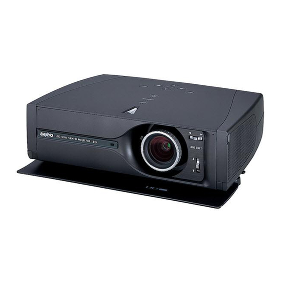
- Page 1 Multimedia Projector PLV-Z3 MODEL Owner’s Manual...
-
Page 2: Features And Design
Features and Design This Multimedia Projector is designed with the most advanced technology for portability, durability, and ease of use. This projector utilizes built-in multimedia features, a palette of 16.77 million colors, and matrix liquid crystal display (LCD) technol- ogy. ◆... -
Page 3: Table Of Contents
Table of Contents Features and Design Video Input Input Source Selection (Video, S-Video, Component1/2,HDMI) Table of Contents Video System Selection Image Level Selection To the Owner Image Level Adjustment Screen Size Adjustment Safety Instructions Computer Input Air Circulation Installing the Projector in Proper Position Input Source Selection Moving the Projector Computer System Selection... -
Page 4: To The Owner
To the Owner Before operating this projector, read this manual thoroughly Safety Precaution and operate the projector properly. This projector provides many convenient features and WARNING : TO REDUCE THE RISK OF FIRE OR ELECTRIC functions. Operating the projector properly enables you to SHOCK, DO NOT EXPOSE THIS APPLIANCE manage those features and maintains it in better condition for TO RAIN OR MOISTURE. -
Page 5: Safety Instructions
Safety Instructions All the safety and operating instructions should be read before This projector should be operated only from the type of power the product is operated. source indicated on the marking label. If you are not sure of the type of power supplied, consult your authorized dealer or Read all of the instructions given here and retain them for later local power company. -
Page 6: Air Circulation
Safety Instructions Air Circulation Installing the Projector in Proper Position Openings in the cabinet are provided for ventilation and to Install the projector properly. Improper Installation may reduce ensure reliable operation of the product and to protect it from the lamp lifetime and cause a fire hazard. overheating, and these openings must not be blocked or covered. -
Page 7: Compliance
Model Numbers : PLV-Z3 Trade Name : Sanyo Responsible party : SANYO FISHER COMPANY Address : 21605 Plummer Street, Chatsworth, California 91311 Telephone No. : (818)998-7322 AC POWER CORD REQUIREMENT The AC Power Cord supplied with this projector meets the requirement for use in the country you purchased it. -
Page 8: Part Names And Functions
Part Names and Functions Exhaust Vent Front CAUTION Hot air is exhausted from the exhaust vent. Do not put heat-sensitive objects near this side. Air Intake Vent (The two arrows show air flow.) Top Controls and Indicators Front Cover Infrared Remote Receiver Projection Lens Zoom Lever Focus Ring... -
Page 9: Terminal
Part Names and Functions Terminal COMPUTER COMPONENT 1 / 2 Connect the component video output to these jacks. (p16) Connect computer output, or RGB Scart 21-pin video output to this connector. (p17,18) VIDEO Connect the composite video output from video equipment to this jack. -
Page 10: Top
Part Names and Functions w e r ON-OFF POWER WARNING LAMP REPLACE MENU INPUT SELECT POWER ON–OFF button MENU button Turns the projector on or off. (p19) Opens or closes the On-Screen Menu. (p22) POINT (Upe/Downd/Left7/Right8) button POWER indicator Selects an item or adjusts value in the On-Screen Menu. These Flashes red until the projector gets ready to be turned on. -
Page 11: Remote Control
Part Names and Functions LIGHT button Lights the buttons on the remote control for about 10 seconds. Remote Control MENU button Opens or closes the On-Screen Menu. (p22) POINT (UP/DOWN/LEFT/RIGHT) button Selects an item or adjusts value in the On-Screen Menu. These are also used to pan the image in the Digital zoom mode. -
Page 12: Remote Control Operating Range
Part Names and Functions Remote Control Operating Range Point the remote control toward the projector (Infrared Remote Receiver) whenever pressing any button. Maximum operating range for the remote control is about 16.4’ (5m) and 60° in front of the projector. 16.4’... -
Page 13: Installation
Installation Positioning the Projector This projector is designed to project on a flat projection surface and can be focused from 3.9’(1.2m) - 20.0’(6.1m). Refer to the figure and the table below for the screen size and the distance between the projector and the screen. 20.0' (6.1m) 15.1' (4.6m) (Inch Diagonal) -
Page 14: Connecting The Ac Power Cord
Installation Connecting the AC Power Cord This projector uses nominal input voltages of 100-120 V or 200-240 V AC. This projector automatically selects the correct input voltage. It is designed to work with single-phase power systems having a grounded neutral conductor. To reduce risk of electrical shock, do not plug into any other type of power system. -
Page 15: Moving The Lens
Installation Moving the Lens The projection lens can be moved up, down, left, and right with the manual lens shift function. This function makes it easy to provide a projected image where you want. Turn the lens shift ring (left/right) left/right to move the lens leftward / Lens Shift Ring rightward. -
Page 16: Connecting To Video Equipment (Video, S-Video)
Installation Connecting to Video Equipment (Video, S-Video) Video, S-video Use the supplied video cable or a s-video cable (not supplied). Video Equipment Composite S-VIDEO Video Output Output Video Cable S-video (RCA x 1) Cable VIDEO S-VIDEO COMPU COMPUTER COMPONENT COMPONENT HDMI Connecting to Video Equipment (Component) Component... -
Page 17: Connecting To Video Equipment (Hdmi)
Installation Connecting to Video Equipment (HDMI) HDMI Use a HDMI cable (option) for HDMI. Video Equipment HDMI Video Output HDMI Cable HDMI COMPUTER COMPUTER COMPONENT COMPONENT HDMI HDMI Connecting to Video Equipment (RGB Scart) RGB Scart Video Equipment Use a Scart-VGA cable (option). RGB Scart 21-pin Output Scart-VGA Cable... -
Page 18: Connecting To A Computer
Installation Connecting to a Computer Computer (Analog) IBM-compatible or Macintosh computer Use a VGA cable (option) or a DVI-VGA cable (commercially available). Monitor Out DVI-VGA VGA Cable Cable COMPUTER COMPUTER COMPONENT HDMI HDMI NOTE ● See page 59 for ordering optional cables. NOTE When connecting the cable, the power cords of both the projector and the external equipment should be disconnected... -
Page 19: Basic Operation
Basic Operation Turning On the Projector Complete peripheral connections (with a computer, VCR, etc.) before turning on the projector. Connect the projector's AC power cord into an AC outlet and open the front cover. Turn the Main On / Off switch on, and the Open the front cover. -
Page 20: Zoom Adjustment
Basic Operation Zoom Adjustment Move the Zoom Lever to zoom in and out. Zoom Lever Focus Adjustment Rotate the Focus Ring to adjust the projected picture focus. Focus Ring... -
Page 21: Keystone Adjustment
Basic Operation Keystone Adjustment If a projected picture has keystone distortion, correct the image with KEYSTONE adjustment. Press the KEYSTONE ▲/▼ button on the remote control or select the Keystone in the Setting Menu (p41). The Keystone dialog box appears. Correct keystone distortion by pressing the KEYSTONE ▲/▼... -
Page 22: On-Screen Menu
Basic Operation On-Screen Menu You can control and adjust this projector through the On-Screen Remote Control Menu. Refer to the following pages to operate each adjustment LIGHT on the On-Screen Menu. RESET MENU button CANCEL MENU POINT button Press the MENU button on the top control or on the remote control to display the On-Screen Menu (Main Menu). -
Page 23: Menus
Basic Operation Menus VIDEO MENUS Input Menu: selects input source. (p24-25) AV System Menu: selects video system from AUTO, PAL, SECAM, NTSC, NTSC4.43, PAL-M, PAL-N, 1080i, 1035i, 720p, 575p, 480p, 575i, 480i. (p26) Image Select Menu: selects image level from Creative cinema, Pure cinema, Natural, Video, Dynamic, Powerful, Graphic, User Image 1 ~ 4. -
Page 24: Video Input
Video Input Input Source Selection (Video, S-Video, Component1/2, HDMI) Direct Operation Choose Input source by pressing the INPUT button on the top control or INPUT buttons on the remote control. Top Control Remote Control VIDEO CLEAR DARK INPUT S-VIDEO U - 1 U - 2 SELECT USER SETTING... - Page 25 Video Input Menu Operation Select the Input Source with the Point Up/Down button, and Input Source then press the Point Right button to enter the sub-menu. Select Input source with the Point Up/Down button and then press SELECT button. Video When video input signal is connected to the VIDEO jack, select Video.
-
Page 26: Video System Selection
Video Input Video System Selection Select the AV System Menu with the Point Up/Down button, AV System Menu (Video or S-Video) and then press the Point Right button to enter the sub-menu. Choose the system that you want to select with the Point Up/Down button and then press the SELECT button. -
Page 27: Image Level Selection
Video Input Image Level Selection Direct Operation Select an image level among Creative cinema, Pure cinema, Natural, Remote Control Video, Dynamic, Powerful, Graphic, User Image 1 ~ 4 by pressing the CANCEL MENU IMAGE buttons (CLEAR, DARK, and U-1-4 buttons) on the remote control. -
Page 28: Image Level Adjustment
Video Input Image Level Adjustment Select the Image Adjust Menu with the Point Up/Down button, Image Adjust Menu and then press the Point Right button to enter the sub-menu. Select an item with the Point Up/Down button and press the Point Left/Right button to adjust the item. - Page 29 Video Input This arrow indicates that there Progressive are previous items. Select this item and press the Point Up Interlace video signal can be converted to a progressive signal. button to go to the previous Off ···· Not activated. item. L1 ····...
-
Page 30: Screen Size Adjustment
Video Input Screen Size Adjustment This projector has a useful function to resize a projected screen. Select the Screen Menu with the Point Up/Down button, and Screen Menu then press the Point Right button to enter the sub-menu. Select an item with the Point Up/Down button and press the Point Left/Right button to set the screen size. - Page 31 Video Input Normal through Normal through Provides an image with no modification. (You can enjoy a high-quality image though the projected image is small.) Natural wide 1 Natural wide 1 Modifies an image of 4 : 3 aspect ratio to fit the screen size (16 : 9 aspect ratio).
-
Page 32: Computer Input
Computer Input Input Source Selection Direct Operation Choose INPUT source by pressing the INPUT button on the top Top Control Remote Control control or PC button on the remote control. VIDEO CLEAR DARK INPUT S-VIDEO U - 1 U - 2 SELECT USER SETTING COMPO.1... -
Page 33: Computer System Selection
Computer Input Computer System Selection This projector can detect most of the current computer systems with the Multi-scan system and the Auto PC adjustment function provided in the projector. When selecting computer input, the projector automatically displays the most proper image for the input signal. -
Page 34: Computer Adjustment (Auto)
Computer Input Computer Adjustment (Auto) The Auto PC adjustment function is provided to automatically adjust Fine sync, Total dots, Horizontal, and Vertical to conform to your computer. This function can be operated as follows. Select the PC Adjust Menu with the Point Up/Down button, and PC Adjust Menu then press the Point Right button to enter the sub-menu. -
Page 35: Computer Adjustment (Manual)
Computer Input Computer Adjustment (Manual) Some computers employ special signal formats which may not be tuned by Multi-scan system of this projector. This projector has Manual PC Adjustment to enable you to precisely adjust several parameters to match those signal formats. The projector has 5 independent memory areas to memorize those parameters manually adjusted. - Page 36 Computer Input Display area Select Store to store adjust- Select the resolution at the Display area dialog box. ment data. Display area H Adjusts the horizontal area displayed by this projector. Press the Point Left/Right button to decrease/increase value. Display area V Adjusts the vertical area displayed by this projector.
-
Page 37: Image Level Selection
Computer Input Image Level Selection Direct Operation Select an image level among Creative cinema, Pure cinema, Natural, Remote Control Video, Dynamic, Powerful, Graphic, User Image 1 ~ 4 by pressing the MENU CANCEL IMAGE buttons (CLEAR, DARK, and U-1-4 buttons) on the remote control. -
Page 38: Image Level Adjustment
Computer Input Image Level Adjustment Select the Image Adjust Menu with the Point Up/Down button, Image Adjust Menu and then press the Point Right button to enter the sub-menu. Select an item with the Point Up/Down button and press the Point Left/Right button to adjust the item. - Page 39 Computer Input This arrow indicates that there Lamp mode are previous items. Select this item and press the Point Up This function allows you to change brightness of the screen. button to go to the previous Bright mode ..Normal brightness item.
-
Page 40: Screen Size Adjustment
Computer Input Screen Size Adjustment This projector has a useful function to resize a projected screen. Select the Screen Menu with the Point Up/Down button, and Screen Menu then press the Point Right button to enter the sub-menu. Select an item with the Point Up/Down button and press the Point Left/Right button to set the screen size. -
Page 41: Setting
Setting Setting Select the Setting Menu with the Point Up/Down button, and Setting Menu (Language) then press the Point Right button to enter the sub-menu. Select an item with the Point Up/Down button to set various settings. Language The language used in the On-Screen Menu is available in English, German, French, Italian, Spanish, Portuguese, Dutch, Swedish, Russian, Chinese, Korean, or Japanese. - Page 42 Setting Advanced menu When this function is On, Advanced menu in Image level adjustment (both Video and computer input) can be selected. See Image level adjustment (p.29,39) for details. Capture Logo This function decides what to be displayed when starting up. ····...
- Page 43 Setting This arrow indicates that there Power management are previous items. Select this item and press the Point Up but- For reducing power consumption as well as maintaining the lamp ton to go to the previous item. life, the Power management function turns off the projection lamp when the input signal is interrupted and no button is pressed for 30 Power management seconds or more.
- Page 44 Setting Factory default Lamp counter reset This function is used to reset the lamp replace counter. When replacing the projection lamp, reset the lamp replace counter by using this function. See page 51 for operation. Factory default This function returns all setting values except for the lamp counter to the factory default settings.
-
Page 45: Maintenance And Cleaning
Maintenance and Cleaning Warning Indicator The WARNING indicator shows the state of the function which protects the projector. Check the state of the WARNING indicator and the POWER indicator to take proper maintenance. The projector is shut down and the WARNING indicator is flashing red When the temperature inside the projector exceeds the normal TOP CONTROL temperature, the projector is automatically shut down to protect the... -
Page 46: Cleaning The Rgb Panels
Maintenance and Cleaning Cleaning the RGB panels If some dusts attach to optical parts inside the projector, the brightness could decrease or shadows could appear on the screen and image deterioration could result. This projector equipped with RGB panel cleaning holes on the bottom of the projector to clean the internal parts (such as optical parts) of the projector. - Page 47 Maintenance and Cleaning Clean with using the cleaning function in the Setting menu Pull one of the hole Press MENU button to display the On-Screen Menu and select cover upward gently. the Setting menu by pressing the Point Up/Down button. Then press Point Right button to enter the sub-menu.
-
Page 48: Cleaning The Air Filter
Maintenance and Cleaning Cleaning the Air Filter The air filters prevent dust from accumulating on the surface of the optical elements inside the projector. Should the air filters become clogged with dust particles, it will reduce cooling fans’ effectiveness and may result in internal heat build up and adversely affect the life of the projector. -
Page 49: Replacing The Air Filter
Maintenance and Cleaning Replacing the Air Filter When there is much dust and dirt on the air filter, replace it with a new one following the steps below. After removing the air filter from the projector as described above, remove the replacement filter from the holder. Holds the air filter with both hands, and remove the replacement filter by pulling it up. -
Page 50: Lamp Replacement
ORDER REPLACEMENT LAMP Replacement lamp can be ordered through your dealer. When ordering a projection lamp, give the following information to the dealer. ● Model No. of your projector PLV-Z3 ● Replacement Lamp Type No. POA-LMP86 (Service Parts No. 610 317 5355) -
Page 51: Lamp Replace Counter
Maintenance and Cleaning Lamp Replace Counter Be sure to reset the lamp replace counter after the lamp is replaced. When the lamp replace counter is reset, the LAMP REPLACE indicator stops lighting. Turn the projector on, press the MENU button, and the On- Lamp counter reset Screen Menu will appear. -
Page 52: Appendix
Appendix Troubleshooting Before calling your dealer or service center for assistance, check the items below once again. – Make sure you have properly connected the projector to peripheral equipment as described in “Connecting to Video Equipment” and "Connecting to a Computer" on page16 -18. –... -
Page 53: Indicators And Projector Condition
Appendix Indicators and Projector Condition Check the indicators for projector condition. Indicators Projector Condition POWER LAMP WARNING REPLACE red/green/ orange yellow The Main On/Off switch is off or the AC power cord is unplugged. ✽ The projector is preparing for stand-by. Or the projection lamp is being cooled down. -
Page 54: Menu Tree
Appendix Menu Tree Video Input/Computer Input Video Video Go to System Input S-video Go to System Component 1 Go to System Component 2 Go to System HDMI Go to System Computer Computer Go to System RGB(Analog) RGB(Scart) ✽N/A not applicable - - - Video Input System... - Page 55 Appendix Computer Input System Mode 1 Screen Normal Mode 2 Full SVGA 1 True - - - - Digital zoom ✽Systems displayed in the System Menu vary depending on an input signal. PC Adjust Auto PC adj. Fine sync. 0 ~ 31 Setting Total dots Horizontal...
-
Page 56: Compatible Computer Specifications
Appendix Compatible Computer Specifications Basically this projector can accept the signal from all computers with the V, H-Frequency below mentioned and less than 100 MHz of Dot Clock. H-Freq. V-Freq. H-Freq. V-Freq. ON-SCREEN ON-SCREEN RESOLUTION RESOLUTION (kHz) (Hz) (kHz) (Hz) DISPLAY DISPLAY VGA 1... -
Page 57: Technical Specifications
Appendix Technical Specifications Projector Type Multimedia Projector Dimensions 14.13" x 4.59" x 10.77" (359mm x 116.7mm x 273.5mm) (not including raised portions) (W x H x D) Net Weight 9.0 lbs (4.1 kg) LCD Panel System 0.7” wide TFT Active Matrix type, 3 panels Panel Resolution 1280 x 720 dots Number of Pixels... -
Page 58: Dimensions
Appendix Dimensions Unit : inch (mm) 4.52 (114.7) 14.13 (359) 2.68 (68) 11.8˚ (Max.) ON-OFF POWER WARNING LAMP 10.77 (273.5) REPLACE MENU INPUT SELECT 4.59 (116.7) -
Page 59: Configurations Of Terminal
Appendix Configurations of Terminal Video terminal Terminal : HDMI Pin Configuration TMDS Data 2+ Input Ground (TMDS Clock) Ground (TMDS Data 2) TMDS Clock- Input 1 3 5 7 9 11 13 15 17 19 TMDS Data 2- Input ----- TMDS Data 1+ Input ----- Ground (TMDS Data 1) - Page 60 Printed in Japan Part No. 610 317 4693 (1AA6P1P4651-- M4SA) SANYO Electric Co., Ltd.